Abstract
We demonstrate a fiber oscillator that achieves 3 MW peak power, is easily started, and is environmentally stable. The Mamyshev oscillator delivers 190-nJ pulses that can be compressed externally to 35 fs duration. Accurate numerical modeling of the gain medium provides insight into the behavior and performance of the device.
Keywords: (060.2320) Fiber optics amplifiers and oscillators; (060.3510) Lasers, fiber; (140.7090) Ultrafast lasers
Ultrafast fiber lasers attract considerable interest as an alternative to bulk solid-state lasers due to their efficiency, compactness, and advantages of the waveguide medium. However, the pulse energy is typically limited by the increasing difficulty of stabilizing high-energy, single-pulse evolution.
Pulse evolutions based on a normal-dispersion fiber provide a means of tolerating high nonlinear phase accumulation without sacrificing pulse quality [1]. However, excessive nonlinear phase accumulation causes a pulse in the cavity to split apart (i.e., enter a multi-pulsing regime) and/or spectral/temporal pulse shape distortions. In parallel with this issue, pulses that accumulate high nonlinear phase shifts need to be stabilized by a proportionally strong saturable absorber (SA) [2–4]. If the SA’s modulation depth is too shallow, the pulse evolution can be disrupted by the growth of continuous-wave background (termed CW breakthrough). The SA also plays the vital role in initiating pulse formation from noise.
SAs based on material absorption [5–7] and interference-based SAs [8–10]have been employed in fiber oscillators. Unfortunately, none of these can provide a perfect solution for high-energy pulse stabilization. Material-based SAs are prone to damage in high-power fiber lasers [11]. The transmission-intensity curves of interference-based SAs do not increase monotonically [8–10], and lasers with these tend to emit multi-pulse bursts at the highest energies. Furthermore, only SAs based on nonlinear polarization evolution (NPE) have demonstrated deep enough modulation (often >70%) to support high-energy pulses. However, the use of low-birefringence fibers makes such lasers sensitive to environmental perturbations.
One promising solution for environmentally stable oscillators has its roots in Mamyshev’s proposal to regenerate pulses using spectral broadening followed by offset spectral filtering [12]. While the idea of a mode-locked laser based on offset filters was proposed much earlier [13,14], it did not receive significant attention at that time. More recently, several approaches for short-pulse generation based on the Mamyshev regenerator have been investigated [15–17]. This approach has gained momentum in the past few years, with the demonstration of mode-locked oscillators based on two concatenated Mamyshev regenerators (so-called Mamyshev oscillators) that have achieved nanojoule-scale pulse energies [18–20]. This approach achieves high peak powers in environmentally stable designs based on flexible fibers. The outstanding performance of the Mamyshev oscillator relies primarily on the effective SA created by the concatenated Mamyshev regenerators. Increasing the filter separation increases the modulation depth [15], which allows higher-energy pulses to be stabilized. However, the resulting suppression of low-intensity fluctuations also hinders starting of the oscillator from noise. With small filter separations (~3 nm), the low-intensity attenuation is mild enough to permit starting through signal modulation [18]. Using more moderate (~10 nm) filter separations permits higher steady-state energies, but requires stronger starting methods, such as modulation of the pump power [19]. To achieve the highest pulse energies to-date, an even larger filter separation was required, resulting in none of these mechanisms sufficing to start the laser [20]. Starting that laser requires an ultrashort external seed pulse, which significantly diminishes the attractiveness of the Mamyshev oscillator as a practical device.
Here, we present a simple and reliable method for starting a Mamyshev oscillator that generates pulses with multi-megawatt peak power. The oscillator includes a starting arm that creates a fluctuating field that seeds the mode-locked state. Moreover, we scale the cavity design to a larger fiber core compared to previous work [20] to generate stable, 190-nJ pulses that are dechirped to 35 fs duration, yielding 3 MW peak power. With the incorporated starting cavity, the oscillator is self-seeded and environmentally stable in the mode-locked state.
The oscillator design is based on the normal-dispersion ring cavity presented in [20], with polarization-maintaining (PM) Yb-doped fiber as the gain medium. The cavity (Fig. 1) is constructed by concatenating two Mamyshev regenerators (the two “arms”). The first arm (red dashed box in Fig. 1) is built from fiber with a 6μm core diameter and acts mainly as a lower-energy feedback loop for the second arm. The second arm (blue dashed box in Fig. 1) is constructed from fiber with a 10μm core diameter and acts as a power amplifier after which the main output is taken. The offset bandpass filters that complete the regenerators are placed between the two arms.
Fig. 1.
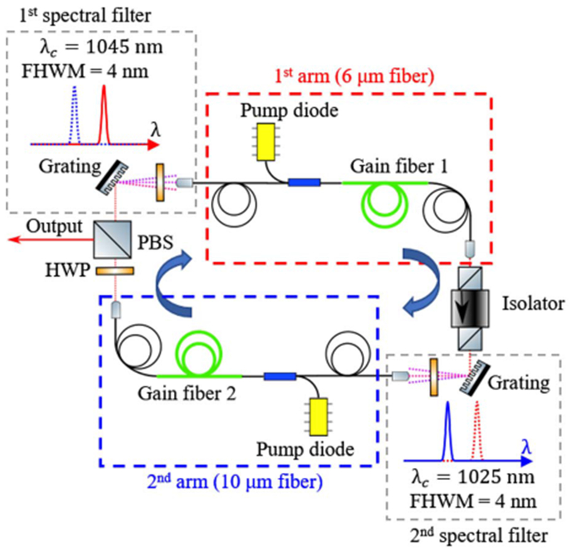
Schematic of the ring Mamyshev oscillator.
To initiate pulsation in the cavity, one needs to create an electric field fluctuation that is strong enough to sustain itself. To generate this fluctuation, we construct a starting arm [Fig. 2(a)] that bypasses the first filter to allow CW lasing inside the oscillator. The starting arm includes a SA that amplifies fluctuations to create the seed pulse. In our experimental realization, a non-PM fiber segment and polarization elements form an effective SA through NPE (marked by a blue box in the starting arm). When the starting arm is engaged [using a flip mirror; Fig. 2(a)] and the SA is adjusted to generate the broadest possible spectrum, noisy Q-switched pulses are generated in the cavity without the first filter. Figure 2(b) shows a typical noisy Q-switched pulse train, measured at the auxiliary output in the starting arm, when the main cavity is blocked [the main cavity is blocked between the polarizing beam splitter (PBS) and first filter to prevent mode locking]. Figure 2(c) shows the spectrum averaged over 50 ms, i.e., over many Q-switched pulses.
Fig. 2.
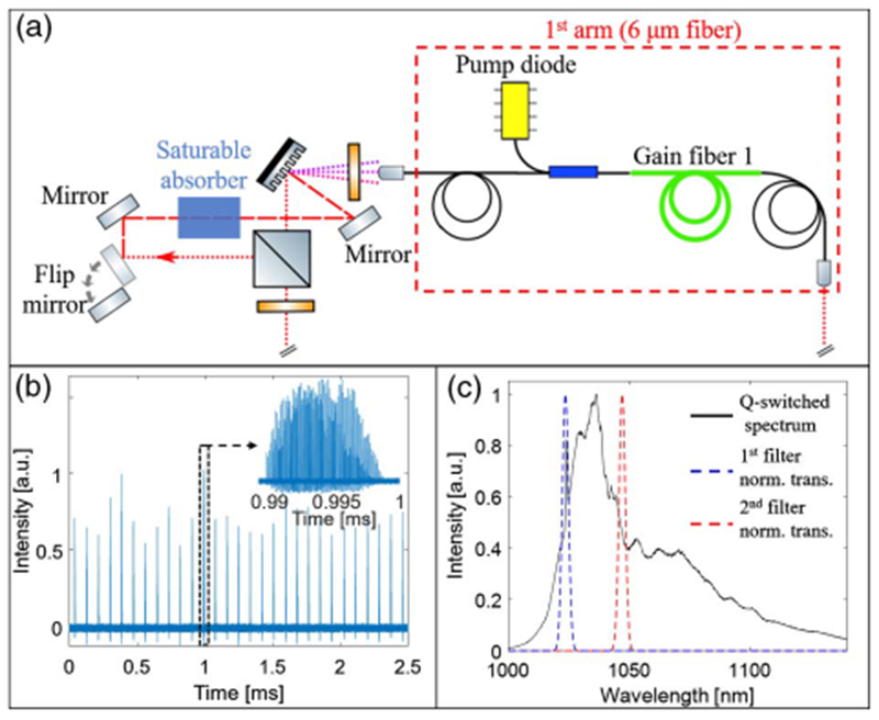
(a) Schematic of the starting arm. The dotted red line in dicates light path in the main cavity, and red dashed line indicates light path when starting arm is engaged (only one arm of the main cavity is shown). (b) Noisy Q-switched pulse train. Inset: expanded view of the pulse marked by black dashed box. (c) Spectrum of the Q-switched pulse train (solid black curve). Dashed blue and red curves correspond to the normalized transmissions of the first and second filters, respectively.
The noisy fluctuations from the starting arm initiate pulsation in the main cavity. Empirically, we find that if the spectrum of the noisy Q-switched state spans the two filter passbands, simply engaging and disengaging the flip mirror starts the mode locking most reliably. The spectra of individual Q-switched pulses may not span the filter passbands, so our empirical observation does not reflect a fundamental requirement for starting. The bandwidth of a noisy pulse is inversely proportional to the shortest temporal fluctuation, which will have high peak power on average. We therefore observe the most reliable self-seeding with the broadest Q-switched spectra, which can be obtained by properly setting the pump power in the first arm and the wave plates that control the SA of the starting arm. A more detailed analysis of the starting mechanism will be the subject of future work.
The main cavity consists only of PM fiber. With the starting arm disengaged, the oscillator is therefore robust against environmental variations [21] in steady-state operation. While the use of NPE makes the starting arm sensitive to the environment, this does not affect the main cavity once the starting arm is disengaged. We anticipate that replacing the NPE with an environmentally stable SA would serve comparably well, and allow even the starting arm to be PM. After initiation, mode locking is self-sustaining and robust, regardless of whether the starting arm is engaged.
Once the oscillator is mode locked, we adjust the output coupling ratio (via the half-wave plate before the PBS in Fig. 1) to obtain a stable pulse train with highest pulse energy. In this state, the oscillator generates 4-ps chirped pulses with energy up to 190 nJ [Fig. 3(a)]. Attempts to reach higher energies cause the pulse train to become unstable. Dechirping the 190-nJ pulses with a grating compressor (1000 lines/mm) yields 35-fs pulses [Fig. 3(b)]. The 75% efficiency of the compressor is accounted for in the peak power plotted in Fig. 3(b). We systematically investigated the performance as a function of the pump power. The pulse energy is varied by changing the pump power in the 10-μm arm only. We verified single-pulse operation and the absence of CW breakthrough for all reported pulse energies. Figure 3(c) shows the variation of the root-mean-square (RMS) bandwidth (blue diamonds), the measured compressed pulse duration (red squares), and the calculated transform-limited (TL) pulse duration (red circles) with the pulse energy, as the pump power is increased. The increasing deviation between the measured and TL duration at high energy can be attributed to uncompensated cubic phase, with contributions from both the oscillator and the grating compressor. Calculations suggest that a compressor with third-order dispersion opposite that of an ordinary grating pair (e.g., a prism or grism compressor [22]) should allow the pulses to be compressed to their transform limit, which would improve the peak power to nearly 5 MW.
Fig. 3.
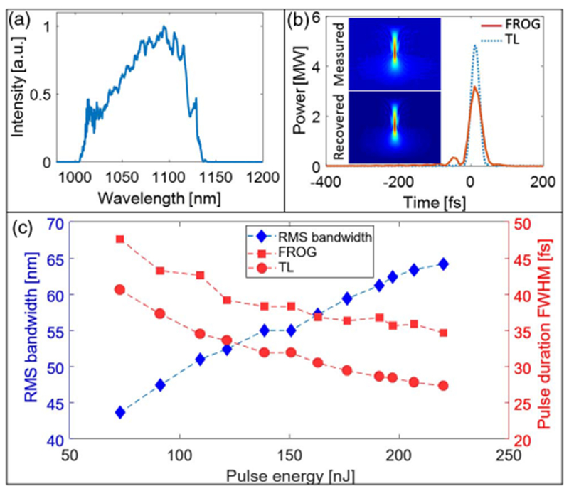
(a) Measured spectrum and (b) dechirped (red solid line) and TL (blue dotted line) pulses for 190 nJ pulse energy. Insets in (b) are measured and reconstructed FROG traces. (c) RMS bandwidth (blue diamonds), FWHM duration of the dechirped pulses (red squares), and TL duration (red circles) for pulse energies between 75 nJ and 220 nJ.
The peak power was verified by launching a known fraction of the dechirped pulse into 1 m of single-mode fiber (SMF) and measuring the spectral broadening induced by self-phase modulation (SPM). The RMS bandwidth is compared with the results of numerical simulations that account for dispersion up to fourth order, SPM, self-steepening, and Raman scattering [Fig. 4(a)]. The simulated and measured bandwidths agree, confirming the peak power scale of Fig. 3(b).
Fig. 4.
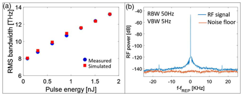
(a) Comparison of the measured spectral broadening of the dechirped pulse (blue circles) in 1 meter of SMF compared with simulations (red squares). (b) RF spectrum of the generated pulse train (blue curve) and instrument noise floor (red curve). RBW: resolution bandwidth; VBW: video bandwidth.
The output pulse train was measured with a radio-frequency (RF) spectrum analyzer. The contrast between the fundamental frequency and secondary modulations offset about 17 kHz from the fundamental is 75 dB [Fig. 4(b)], which indicates stable mode locking. After mode locking is initiated with the starting arm, it routinely sustains itself for at least one day. Continuous operation without appreciable drift of the spectrum has been observed for up to three days, which is the longest period we have monitored.
To understand the pulse evolution in the oscillator, we performed numerical simulations using the standard split-step method. The simulation includes the Kerr nonlinearity, Raman scattering, self-steepening, and second- and third-order dispersion. For accurate modeling, we found that it was critically important to model the Yb gain by solving the rate equations in the steady state [23]. The noisy seed pulse was generated by applying a pseudo-random spectral phase to a Gaussian spectrum with bandwidth of 20 nm, centered at 1030 nm. We verified that for given cavity parameters, the simulation converges to the same solution from different initial pulses. Figure 5 shows results of the simulation for 190-nJ output pulses. The spectrum broadens dramatically in the gain fibers [Figs. 5(a) and 5(b)], as intended. The pulse duration also grows monotonically in both gain fibers. The filters abruptly truncate the pulse in both the spectral and temporal domains.
Fig. 5.
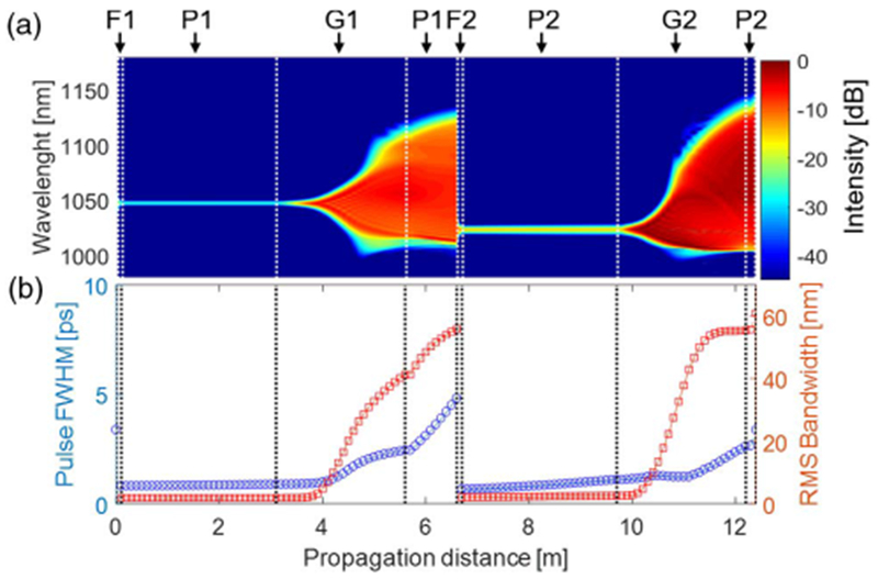
Numerical simulation results for 190 nJ output pulses. (a) Spectral evolution of the pulse in the cavity; P-passive fiber, G-gain fiber, F-filter (indices 1 and 2 correspond to the 6-μm and 10-μm arms, respectively). (b) Evolution of the pulse duration (blue circles) and RMS bandwidth (red squares).
For pulse energies up to 190 nJ, the simulations account well for the observed spectral shapes [Fig. 6(a)]. At higher energies, the experimental spectrum develops structure, and this is accompanied by the instabilities in the pulse train mentioned above. The experimentally measured durations of the dechirped pulses are consistently longer than the simulated durations [respectively, blue squares, same data points as in Fig. 3(c); and blue dashed curve in Fig. 6(b)]. We attribute this discrepancy to the high-order dispersion coefficients of the actual fibers, which are not accounted for in simulations. The simulations predict stable pulse formation for energies up to 500 nJ, at which point pulse splitting occurs. However, in experiments the pulse train becomes unstable above 190 nJ, and an abrupt loss of mode locking occurs above 220 nJ. As this threshold is approached, the agreement between experiments and simulations breaks down, with a series of narrow peaks forming on the red side of the spectrum [Fig. 6(a)]. Given that the limit is clearly the ~200 nJ established experimentally, a revised numerical model will be required to improve the cavity design and perhaps advance this performance limit.
Fig. 6.
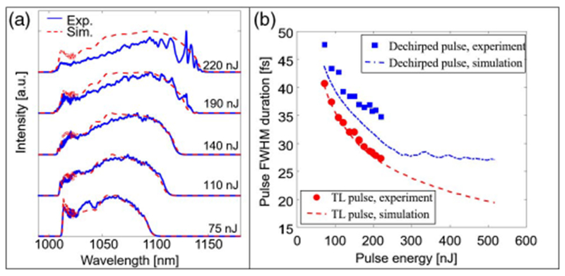
(a) Experimentally measured (blue) and simulated (red) spectra for range of pulse energies. (b) Measured and simulated pulse duration for dechirped and TL pulses.
The pulse energies and peak powers achieved here can be scaled further by established techniques, such as the use of large-mode-area fibers [24] or divided-pulse amplification [25]. These may allow microjoule-level, 100-MW pulses to be obtained directly from an oscillator.
In conclusion, we have demonstrated that a Mamyshev oscillator can be started by simply flipping a mirror to engage a starting arm. An oscillator with this feature generates 35-fs and 190-nJ pulses, for 3 MW peak power. The starting arm and the self-seeding mechanism do not diminish the steady-state mode-locking performance. Numerical simulations suggest that the pulse energy can ultimately be increased up to ~500 nJ, and the pulse duration can be below 30 fs, resulting in ~20 MW peak power. The combination of a simple starting mechanism, environmental stability in the steady state, and the performance reported here make the Mamyshev oscillator an attractive source of ultrashort pulses for applications.
Acknowledgments
Funding.
National Institutes of Health (NIH) (EB002019); National Science Foundation (NSF) (ECCS 1609129); Fonds de Recherche du Québec—Nature et Technologies (FRQNT) (FRQNT CO201310).
REFERENCES
- 1.Chong A, Buckley J, Renninger W, and Wise F, Opt. Express 14, 10095 (2006). [DOI] [PubMed] [Google Scholar]
- 2.Renninger WH and Wise FW, IEEE J. Sel. Top. Quantum Electron. 21, 63 (2015). [DOI] [PMC free article] [PubMed] [Google Scholar]
- 3.Jeon J, Lee J, and Lee JH, J. Opt. Soc. Am. B 32, 31 (2015). [Google Scholar]
- 4.Ma C, Tian X, Gao B, and Wu G, Opt. Commun. 410, 941 (2018). [Google Scholar]
- 5.Keller U, Weingarten KJ, Kartner FX, Kopf D, Braun B, Jung ID, Fluck R, Honninger C, Matuschek N, and Aus der Au J, IEEE J. Sel. Top. Quantum Electron. 2, 435 (1996). [Google Scholar]
- 6.Set SY, Yaguchi H, Tanaka Y, and Jablonski M, IEEE J. Sel. Top. Quantum Electron. 10, 137 (2004). [Google Scholar]
- 7.Martinez A and Sun Z, Nat. Photonics 7, 842 (2013). [Google Scholar]
- 8.Stolen RH, Botineau J, and Ashkin A, Opt. Lett. 7, 512 (1982). [DOI] [PubMed] [Google Scholar]
- 9.Doran NJ and Wood D, Opt. Lett. 13, 56 (1988). [DOI] [PubMed] [Google Scholar]
- 10.Fermann ME, Haberl F, Hofer M, and Hochreiter H, Opt. Lett. 15, 752 (1990). [DOI] [PubMed] [Google Scholar]
- 11.Saraceno CJ, Schriber C, Mangold M, Hoffmann M, Heckl OH, Baer CR, Golling M, Südmeyer T, and Keller U, IEEE J. Sel. Top. Quantum Electron. 18, 29 (2012). [Google Scholar]
- 12.Mamyshev PV, 24th European Conference on Optical Communication. ECOC ‘98 (IEEE Cat. No. 98TH8398) (Telefonica, n.d., 1998), Vol. 1, pp. 475–476. [Google Scholar]
- 13.Keller U, Chiu TH, and Ferguson JF, Opt. Lett. 18, 1077 (1993). [DOI] [PubMed] [Google Scholar]
- 14.Piché M, Proc. SPIE 2041, 358 (1993). [Google Scholar]
- 15.Pitois S, Finot C, Provost L, and Richardson DJ, J. Opt. Soc. Am. B 25, 1537 (2008). [Google Scholar]
- 16.Sun K, Rochette M, and Chen LR, Opt. Express 17, 10419 (2009). [DOI] [PubMed] [Google Scholar]
- 17.North T and Rochette M, Opt. Lett. 39, 174 (2014). [DOI] [PubMed] [Google Scholar]
- 18.Regelskis K, Želudevičius J, Viskontas K, and Račiukaitis G, Opt. Lett. 40, 5255 (2015). [DOI] [PubMed] [Google Scholar]
- 19.Samartsev I, Bordenyuk A, and Gapontsev V, Proc. SPIE 10085, 100850S (2017). [Google Scholar]
- 20.Liu Z, Ziegler ZM, Wright LG, and Wise FW, Optica 4, 649 (2017). [DOI] [PMC free article] [PubMed] [Google Scholar]
- 21.Feng Y, Xu X, Hu X, Liu Y, Wang Y, Zhang W, Yang Z, Duan L, Zhao W, and Cheng Z, Opt. Express 23, 17549 (2015). [DOI] [PubMed] [Google Scholar]
- 22.Kane S and Squier J, J. Opt. Soc. Am. B 14, 661 (1997). [Google Scholar]
- 23.Paschotta R, Nilsson J, Tropper AC, and Hanna DC, IEEE J. Quantum Electron. 33, 1049 (1997). [Google Scholar]
- 24.Baumgartl M, Ortaç B, Lecaplain C, Hideur A, Limpert J, and Tünnermann A, Opt. Lett. 35, 2311 (2010). [DOI] [PubMed] [Google Scholar]
- 25.Lamb ES, Wright LG, and Wise FW, Opt. Lett. 39, 2775 (2014). [DOI] [PMC free article] [PubMed] [Google Scholar]


