Abstract
Many physiological systems involve strong interactions between fluids and solids, posing a significant challenge when modeling biomechanics. The objective of this study was to implement a fluid–structure interaction (FSI) solver in the free, open-source finite element code FEBio, that combined the existing solid mechanics and rigid body dynamics solver with a recently developed computational fluid dynamics (CFD) solver. A novel Galerkin-based finite element FSI formulation was introduced based on mixture theory, where the FSI domain was described as a mixture of fluid and solid constituents that have distinct motions. The mesh was defined on the solid domain, specialized to have zero mass, negligible stiffness, and zero frictional interactions with the fluid, whereas the fluid was modeled as isothermal and compressible. The mixture framework provided the foundation for evaluating material time derivatives in a material frame for the solid and in a spatial frame for the fluid. Similar to our recently reported CFD solver, our FSI formulation did not require stabilization methods to achieve good convergence, producing a compact set of equations and code implementation. The code was successfully verified against benchmark problems from the FSI literature and an analytical solution for squeeze-film lubrication. It was validated against experimental measurements of the flow rate in a peristaltic pump and illustrated using non-Newtonian blood flow through a bifurcated carotid artery with a thick arterial wall. The successful formulation and implementation of this FSI solver enhance the multiphysics modeling capabilities in febio relevant to the biomechanics and biophysics communities.
1. Introduction
The mechanics of deforming solids and flowing fluids are two of the most fundamental aspects of biomechanics. As a result, there has been much recent development in modeling tools that combine both of the classical fields of solid and fluid mechanics, increasing the use of fluid–structure interactions (FSI). FSI can be used as a modeling tool in many areas of biomechanics and biophysics including, but not limited to, cardiovascular mechanics where blood flows through the deforming heart and vasculature [1–3], diarthrodial joint lubrication where pressurized synovial fluid flows between deforming articular layers [4], cerebrospinal mechanics where fluid flow through the ventricular cavities may cause significant deformation of surrounding soft tissues [5–7], vocal fold and upper airway mechanics [8,9], viscous flow over endothelial cells [10,11], canalicular and lacunar flow around osteocytes resulting from bone deformation [12–14], and many applications in biomedical device design [15–18].
A summary of the few available open-source FSI codes suitable for biomechanical modeling is given in Sec. S1 available in the Supplemental Materials on the ASME Digital Collection. febio, a free, open-source finite element software, was developed specifically to address the needs of the biomechanics and biophysics communities. The source code itself is freely available for download. While it can be customized using user-written plug-ins [19], its built-in capabilities are extensive. It offers a broad range of constitutive relations suitable for studying nonlinear, anisotropic, inhomogeneous, hyperelastic, and viscoelastic solid materials that may also undergo tissue damage and remodeling, and also be subjected to a state of prestrain [20–24]. It can describe biological tissues with mixture theory, accounting for interstitial fluid and solute flow in a porous deformable solid matrix, also accommodating chemical reactions [21,25]. It includes robust contact algorithms that handle large deformations and sliding, with or without friction, for elastic, biphasic, and multiphasic materials [26–28].
Recently, we formulated and implemented a novel 3D computational fluid dynamics (CFD) formulation in febio, based on isothermal compressible flow to analyze Newtonian and non-Newtonian viscous fluid mechanics in febio without requiring the use of stabilization methods [29]. Therefore, in this study, we combine these capabilities of febio by including FSI using the framework of mixture theory. The overall goal of combining these features in an open-source platform is to allow users to easily implement new algorithms and share their models with their peer communities. Therefore, this study also places an emphasis on developing a conceptually straightforward and compact set of governing equations for FSI. Because of the novelty of our formulation, we also provide an extensive series of verification and validation problems using this new formulation to illustrate the flexibility of febio and to test our implementation.
Fluid–structure interaction is commonly modeled using two general approaches, employing either a fixed mesh containing the freely flowing fluid through which a solid may move, or separate moving meshes for the fluid and solid that satisfy certain continuity conditions at their interface [30]. The immersed boundary method uses the former approach [31,32] as reviewed in Sec. S2 available in the Supplemental Materials on the ASME Digital Collection. The second common FSI approach is the arbitrary Lagrangian–Eulerian (ALE) formulation [33,34] using the space–time FE method [35–38], also described in more detail in Sec. S2 available in the Supplemental Materials on the ASME Digital Collection. In this study, we develop a novel implementation of FSI, which belongs to the general family of ALE methods. However, we tailor our formulation to eliminate two aspects of the ALE/general space–time FE method that arguably increase the mathematical complexity of that approach, which may discourage nonexpert users and developers from extending the capabilities of an open-source FSI code. First, we note that most CFD codes have adopted the assumption of incompressible flow, relying on methods that satisfy the inf-sup condition [39,40] by using stabilization schemes such as the streamline-upwind/Petrov-Galerkin (SUPG), pressure-stabilizing/Petrov-Galerkin, and Galerkin/least-squares [35,41]. FSI formulations that employ these methods must similarly supplement Galerkin's method with stabilization terms, increasing the mathematical complexity of the formulation and requiring specialized schemes for different element types. In contrast, we previously showed that our isothermal compressible flow formulation automatically satisfies the inf-sup condition without requiring additional stabilization terms, making it easily adaptable to any element type [29]. The FSI formulation presented here similarly avoids the need for such stabilization, thus producing a simpler set of equations. In addition, this formulation successfully adapts the generalized-α method for temporal discretization used in other ALE formulations [38,42,43], where the user can choose to either conserve energy, at the potential cost of perpetuating dynamic disturbances, or dampen higher frequencies. As in prior implementations, optimal behavior and results are problem-dependent.
Second, the space–time FE method provides an elaborate mathematical framework to deal with spatial and temporal discretization of material and spatial domains, whose description (e.g., Ref. [38]) may appear daunting to many finite element practitioners. In this study, we employed a mixture theory approach to simplify our FSI formulation without compromising mathematical rigor. Mixture theory is a general framework for modeling mixtures of solid and fluid constituents [44–47]; its application to biomechanics has led to significant advances in soft tissue mechanics [48–52]. The mixture framework in febio has been highly successful for modeling deformable porous media [20,53], including neutral [27,54] and charged solutes in multiphasic mixtures [25], and chemical reactions among solutes and solid constituents [21]. Thus, a feature already implemented in febio is the interaction of solid domains with biphasic domains. A biphasic domain consists of a solid–fluid mixture where the solid matrix is porous and deformable, having non-negligible stiffness, and where the frictional drag between fluid and solid is far more significant than the viscous friction within the fluid. The solid matrix nodes of a biphasic domain are typically shared with the nodes of adjoining solid domains so that the solid displacement is continuous at those interfaces. Alternatively, this continuity of the solid displacement may be enforced with a contact interface [26].
Our proposed FSI approach shares a conceptual analogy to the fluid–solid interactions in a biphasic medium, capitalizing on our extensive expertise in finite element modeling of mixture domains. In a biphasic medium, fluid and solid material points coexist in an elemental region at any given time; each material point has its own independent motion; hence, a relative velocity between the fluid and solid may be defined. In the finite element code implementation, the solid constituent is described in a material frame and the fluid constituent in a spatial frame. Hence, the finite element mesh follows the motion of the solid (i.e., each finite element node or integration point describes a solid material point), whereas the fluid flows past these material points with a relative velocity. The mixture framework provides the foundation for evaluating material time derivatives in a material frame for the solid and in a spatial frame for the fluid. In our FSI formulation, we model the fluid domain as a special case of a biphasic medium where the porous solid domain is assumed to have negligible stiffness, zero mass, and zero friction with the viscous fluid. The role of the porous solid is to define the now deformable mesh through which the fluid flows and to transfer the deformations and tractions imposed across solid–fluid interfaces to surrounding solid domains. These surrounding solid domains may deform due to conditions prescribed on their boundaries and as a result of the tractions generated by the fluid along the fluid–solid interfaces. Boundary conditions may also be prescribed directly on the fluid domains, such as moving boundaries. As such, our fluid-FSI formulation belongs to the family of ALE schemes; however, the spatio-temporal discretization of the mixture domain employs fundamental concepts of mixture theory, using the material time derivative following the motion of the mesh to considerably simplify the governing equations and FSI finite element formulation.
2. Finite Element Implementation
In our formulation, the fluid domain is strictly a solid–fluid mixture; we denote this domain by Ωf and call it the fluid-FSI domain to emphasize that its mesh is deformable. In the current implementation, this domain may be surrounded by one or more impermeable solid domains Ωs whose material may be hyperelastic, viscoelastic, or even rigid, undergoing large deformations or motions. The movable and deformable interfaces between Ωf and Ωs are denoted by Γfs; these represent the boundaries across which fluid–structure interactions occur. The remaining boundaries of Ωf are denoted by Γf; these boundaries may also move and deform. In most applications, the solid meshes of Ωf and Ωs may be continuous across Γfs, meaning that the finite elements of these domains share common nodes and solid displacement degrees-of-freedom on Γfs. However, it is also possible to model Γfs as tied interfaces joining disparate meshes, making it easy to select different element types or mesh refinements for Ωf and Ωs, though we do not examine this specific implementation here. The derivations presented below address the analysis of the fluid-FSI domains Ωf; the analysis of domains Ωs was described previously [20].
2.1. Governing Equations.
We model the domain Ωf as a mixture of an isothermal compressible viscous fluid and an isothermal hyperelastic compressible porous solid, where the solid motion represents the mesh motion. The solid constituent has zero mass density (ρs = 0), and negligible (but nonzero) elasticity to regularize the mesh motion. The fluid flows through this mesh, unimpeded by the porous solid. In particular, in this FSI model, there is no frictional interaction between the fluid and solid materials inside the mixture domain (i.e., no Darcy-Brinkman type of friction), but the no-slip boundary condition may be prescribed on boundaries Γfs of the mixture domain, where applicable.
The momentum balance of the fluid is
| (2.1) |
where ρf is the fluid density, is the fluid Cauchy stress, b is the body force per mass acting on the fluid, and af is the fluid acceleration, given by the material time derivative of the fluid velocity vf in the spatial frame
| (2.2) |
where is the fluid velocity gradient. Since there are no interactions between the fluid and porous solid in our FSI implementation, the interactive momentum supply term that normally appears in the momentum balance equation of a mixture constituent [55] is set to zero. In principle, the same form of the momentum equation may be used for the solid as that of Eq. (2.1) (substituting f with s). However, since we are assuming that ρs = 0, the momentum for the solid reduces to
| (2.3) |
where is the solid Cauchy stress (the stress caused by the mesh deformation).
We model the fluid as isothermal and compressible, consistent with our earlier CFD implementation [29]. Thus, the fluid stress may be separated into the elastic (thermodynamic) pressure p(Jf), which only varies with the fluid volume ratio Jf as required by the axiom of entropy inequality, and the viscous stress
| (2.4) |
As done in our CFD solver [29], we integrate the mass balance for the fluid to produce
| (2.5) |
where is a material constant representing the fluid density in the reference state (e.g., under ambient pressure) and is the Jacobian of the fluid deformation, where Ff is the fluid deformation gradient. Since we have introduced Jf as an additional kinematic variable, we need to solve for it using the kinematic constraint between Jf and the fluid velocity vf
| (2.6) |
expressed here in the spatial frame; this relation is derived by taking the material time derivative of Ff following the fluid motion.
The mesh of the fluid-FSI domain is defined on the solid component of the mixture. Therefore, we denote the relative velocity between the fluid and solid by
| (2.7) |
(This term is generally called the convective velocity c in standard ALE formulations [56].) Since the solid constituent has zero volume fraction in this specialized mixture, based on our assumption that the solid has zero mass density, this expression also represents the volumetric flux of fluid relative to the solid. We choose to define the nodal DOFs in the mixture domain Ωf to be the relative fluid velocity w, the fluid dilatation ef = Jf − 1, and the solid displacement u, which is related to the solid velocity via , with the dot operator denoting the material time derivative following the motion of the solid. All three nodal degrees-of-freedom represent kinematic variables describing the motion and deformation of fluid and solid constituents of Ωf. The choice of w is motivated by the fact that the no-slip condition can be prescribed easily on interfaces Γfs by letting w = 0. The choice of ef instead of Jf is motivated by the fact that initial and boundary conditions ef = 0 are more convenient to handle in a numerical scheme than Jf = 1. (For notational convenience, we will continue using Jf in the equations below, instead of ef.) Thus, the fluid velocity has to be evaluated from the nodal DOFs using
| (2.8) |
It follows that the fluid velocity gradient also needs to be obtained from
| (2.9) |
where and . The fluid acceleration may now be rewritten in terms of the DOFs as
| (2.10) |
where
| (2.11) |
are the material time derivatives of the solid and relative fluid velocities in the spatial frame, following the motion generated by vs [55]. We conveniently use this material time derivative (instead of the material time derivative following the motion generated by vf, which was employed in Eqs. (2.2) and (2.6)) since we define the mesh of Ωf on the solid constituent. Subsequently, when we evaluate integrals over finite element domains defined in the material frame of the solid, these material time derivatives following the motion generated by vs conveniently reduce to partial time derivatives in the solid material frame. This ability to distinguish among material time derivatives following the motions of various mixture constituents is a strength of the mixture framework and one of the primary reasons for adopting it here. A similar scheme was used in our previous implementation of solute transport within deformable porous domains, to account for the motion of solutes relative to the porous solid matrix [25,54].
Similarly, the kinematic constraint relating Jf and vf may be rewritten as
| (2.12) |
where
| (2.13) |
is the material time derivative of Jf in the spatial frame, following the motion generated by vs. Finally, as done in our prior studies of biphasic and multiphasic materials [25,26,54], we find it numerically more accurate to use the kinematic identity
| (2.14) |
wherever appears in the governing equations, where is the Jacobian of the solid deformation and is the solid deformation gradient.
In summary, our governing equations for the mixture domain Ωf are
| (2.15) |
2.2. Virtual Work and Weak Form.
The virtual work statement is δW = 0, where the virtual work integral for a Galerkin finite element formulation [57] is given by
| (2.16) |
These integrals are evaluated in the current configuration of Ωf; is the virtual solid velocity, δw is the virtual relative fluid velocity, and δJf is the virtual fluid energy density (see explanation of δJf in the Appendix of Ref. [29]). Using the divergence theorem, the weak form of this statement may be written as the difference δW = δWext − δWint between the external virtual work δWext and the internal virtual work δWint, where
| (2.17) |
and
| (2.18) |
Recall that . In the expression for δWext, we note that is the solid traction, is the fluid viscous traction, and is the normal component of the relative fluid velocity on the boundary ∂Ωf, whose outward unit normal is n. These variables represent the natural boundary conditions for this formulation. If boundary conditions are not set explicitly on ∂Ωf or portions thereof, the natural boundary conditions are thus ts = 0, tτ = 0 and wn = 0. Essential boundary conditions are prescribed on the solid displacement u, relative fluid velocity w, and fluid dilatation ef. In particular, a no-slip boundary condition may be prescribed on Γfs by setting w = 0. A symmetry plane may be prescribed with the essential boundary condition and the natural boundary conditions tτ = 0 and wn = 0.
Since we need some small elasticity to produce a nonzero and regularize the deforming mixture mesh in Ωf, prescribing u on ∂Ωf may produce a negligible but nonzero solid traction, ts ≈ 0 on that portion of the boundary. In general, the mixture traction is defined as , where is the fluid traction. Because of the way we chose to split the internal and external virtual work in Eqs. (2.17) and (2.18), neither t nor tf is a natural boundary condition in this formulation. A desired value for tf may be prescribed using a combination of the natural boundary condition tτ and the essential boundary condition Jf such that p(Jf) produces the desired elastic pressure.
Similarly, a desired value of t is prescribed by setting the values of ts (natural) and tf (combination of natural and essential). There are two general scenarios where t needs to be prescribed in this manner: (1) When a fluid boundary Γf represents a free surface (such as the fluid surface in channel flow), the mixture traction should be set to zero on that boundary, t = 0. In that case, it is necessary to explicitly enforce ts = –tf as a traction boundary condition on the solid constituent. Both of these tractions will have negligibly small magnitudes; nevertheless, this condition must be enforced explicitly to impart the free fluid surface its natural shape. (2) At a fluid–solid interface Γfs, the mixture traction t acting on this interface must be equal and opposite to the traction acting on the surrounding solid domain Ωs. Since u is continuous across Γfs, either due to shared nodes or the enforcement of a tied interface, it is only necessary to supplement the traction on Ωs with –tf.
For both of these cases, the resulting virtual work on the solid domain is
| (2.19) |
where the elemental area da on Γfs may be evaluated from the covariant basis vectors gα (α = 1, 2),
| (2.20) |
where
| (2.21) |
and is the parametric representation of Γfs, defined on the solid constituent. The outward normal n to Ωf on Γfs is evaluated from
| (2.22) |
As a result, the virtual work can be rewritten as
| (2.23) |
In febio, this boundary condition is called fluid-FSI traction, which the user must explicitly prescribe on deformable interfaces Γfs.
2.3. Linearization and Spatial Discretization.
The solution of the nonlinear equation δW = 0 is obtained by linearizing this relation as
| (2.24) |
where the operator represents the directional derivative of δW at along an increment Δ u of u, Δ w of w, or ΔJf of Jf [57]. The details of this linearization are presented in Sec. S3 available in the Supplemental Materials on the ASME Digital Collection. The constitutive relations employed in our formulation are described in Sec. S4 available in the Supplemental Materials on the ASME Digital Collection. The spatial discretization in terms of nodal degrees-of-freedom is also presented in Sec. S5 available in the Supplemental Materials on the ASME Digital Collection. In addition, the temporal discretization is presented in Sec. S6 available in the Supplemental Materials on the ASME Digital Collection. The linearization of the FSI interface traction, along with specialized boundary conditions, which were defined for a fixed CFD domain in our previous study [29], such as backflow and tangential stabilization and flow resistance, is also rederived in Sec. S7 available in the Supplemental Materials on the ASME Digital Collection to account for moving boundaries in an FSI analysis. Details on the FSI solver itself are included in Sec. S8 available in the Supplemental Materials on the ASME Digital Collection. Finally, we describe the verification of fluid mass conservation based on our governing equations in Sec. S9 available in the Supplemental Materials on the ASME Digital Collection.
3. Verification and Validation
In this section, we report the results of selected FSI benchmark problems described in the paper by Bathe and Ledezma [58]. These problems investigated how well our formulation handles the strong coupling of the fluid and solid domain, moving boundaries, large deformations with the fluid and solid domains, and solid domains sandwiched by two fluid domains. We also replicated the free-surface wave propagation problem analyzed by Hughes et al. [33] and analyzed energy dissipation for various values of ρ∞. We supplemented these benchmark problems with the modeling of squeeze-film lubrication between flat parallel plates for which an analytical solution can be obtained by solving the Reynolds equation [59]. We also used this problem to show mesh convergence by comparing with the analytical solution. Then, we illustrated the capabilities of febio with a model of the bifurcated carotid artery where the arterial wall was an anisotropic, heterogeneous, multilayered, and fiber-reinforced composite (two fiber families) described by Holzapfel's material model [60]; we modeled the blood as a Carreau fluid, to illustrate that our formulation can easily account for non-Newtonian behavior. We also illustrated one case where adipose tissue was used to constrain the bifurcated artery, as occurs physiologically. We also examined the importance of using realistic boundary conditions to achieve physically meaningful results, which also demonstrated the flexibility that febio has to offer with material models and boundary conditions. Finally, we reported a validation of our FSI implementation by comparing model predictions and experimental measurements of the flow rate in a peristaltic pump, at different angular velocities of the rollers. This example emphasized the incorporation of rigid bodies and contact algorithms within the FSI module. Unless specified otherwise, all analyses were transient, using a Newtonian fluid with zero bulk viscosity and ρ∞ = 0 for the generalized-α time integration scheme; the solid constituent of Ωf used a compressible Neo-Hookean material [57] with Young's modulus E = 10−9 Pa, and Poisson's ratio ν = 0. Equations were solved using Newton's method with Broyden updates; solver settings were the same as described in our recent CFD study [29] (also see Supplemental Materials on the ASME Digital Collection.).
3.1. One-Dimensional Slip Piston.
This 1D analysis examined the strong coupling between the fluid domain Ωf and the solid domain Ωs at the interface Γfs [58]. Details of the model geometry, boundary conditions, and material properties can be found in Fig. 9 of Ref. [58]. Briefly, a deformable Mooney–Rivlin elastic solid piston pushes a column of fluid out of an opening, which is kept at ambient (zero) pressure (Fig. 1); the back of the elastic solid piston is imparted a linearly increasing velocity and the fluid slips along the walls of its domain. The displacement and velocity of the fluid–solid interface Γfs, and the mixture traction normal to Γfs, were examined and compared between febio and Fig. 10 of Ref. [58]. The febio model had 48 nodes, 11 elements, and 124 degrees-of-freedom. Results are shown in Fig. 2, demonstrating good agreement for all three measures.
Fig. 1.
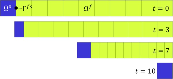
One-dimensional slip piston analysis, showing the mesh at times t = 0, 3, 7, and 10 s. A constant velocity was prescribed on the left boundary of Ωs and the fluid pressure was set to zero at the right boundary of Ωf. The side walls of Ωf were set to slip.
Fig. 10.
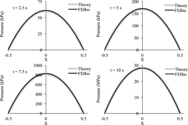
Squeeze-film lubrication of flat parallel plates: Comparison of febio fluid pressure results against the analytical solution of the Reynolds equation, as a function of normalized length X, at selected time points
Fig. 2.
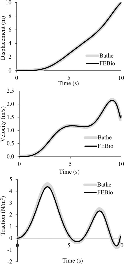
One-dimensional slip piston analysis, comparing febio results with those of Bathe and Ledezma [58] for the displacement, velocity, and normal traction at the fluid–solid interfaceΓfs
3.2. Moving Boundary Piston-Cylinder Problem.
This moving boundary problem was described in Fig. 5 of Ref. [58]. It only includes a fluid domain Ωf, consisting of the cylindrical chamber of a piston-cylinder system, feeding into a narrower stationary cylindrical tube; only one-quarter of the geometry was modeled to take advantage of symmetry (Fig. 3). In the febio model there were 12,073 nodes, 10,080 elements, and 73,941 degrees-of-freedom. All walls were nonslip and the end of the narrow tube was kept at ambient (zero) pressure. The wall representing the piston surface moved at a constant velocity. The fluid pressure and axial fluid velocity along the centerline of the cylindrical geometry were examined and compared between febio and Fig. 6 of Ref. [58]. Results are shown in Fig. 4, demonstrating good agreement at all reported time points.
Fig. 5.
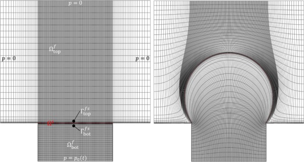
Bubble inflation problem, showing mesh in reference configuration (left) and final configuration at time t = 0.25 (right). The pressure was prescribed as a linearly increasing function of time p0(t) at the bottom face of .
Fig. 3.
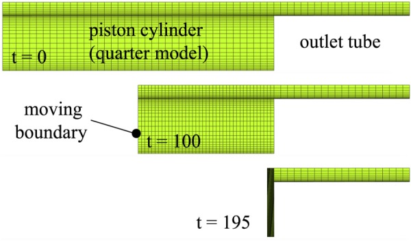
Moving boundary piston-cylinder problem, showing the mesh of the quarter model at times t = 0, 100, and 195 s. The fluid pressure was set to zero at the rightmost boundary of the outlet tube. The piston face, represented by the moving boundary, was imparted a constant velocity. All internal faces of the piston cylinder and tube were set to no-slip.
Fig. 6.
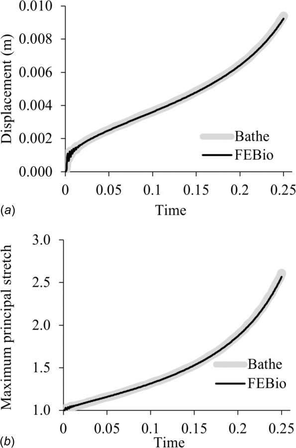
Bubble inflation problem, comparing febio results to those of Bathe and Ledezma [58] for (a) the vertical displacement and (b) the first principal stretch of the top of the bubble
Fig. 4.
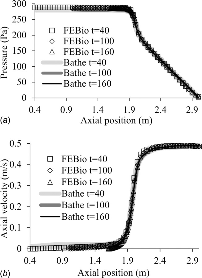
Moving boundary piston-cylinder problem, comparing febio results with those of Bathe and Ledezma [58] for (a) the fluid pressure and (b) the axial fluid velocity, along the centerline of the piston cylinder and tube at times t = 40, 100, and 160
3.3. Bubble Inflation Problem.
This bubble inflation problem was described in Fig. 13 of Ref. [58]. It tests for large deformations in both fluid and solid domains. It includes two fluid domains, and , separated by a thin Mooney–Rivlin elastic solid domain Ωs discretized with solid (hexahedral) elements (Fig. 5). The left, right, and top surfaces of were exposed to ambient conditions (zero pressure), whereas the bottom surface of was subjected to a fluid pressure that increased linearly with time. No-slip conditions were imposed on the bottom wall of , the side walls of , and the fluid–solid interfaces and on both sides of Ωs. The model was run with time-step Δt = 0.001 s until t = 0.25 s. The febio model had 26,276 nodes, 12,842 elements, and 127,646 degrees-of-freedom. The mesh deformation at the final time point is shown in Fig. 5 and may be compared to Fig. 13 of Ref. [58]. The time evolution of the maximum principal stretch and vertical displacement at the membrane center were compared between febio and Fig. 14 of Ref. [58], showing good agreement (Fig. 6).
Fig. 13.
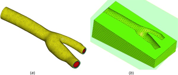
(a) Mesh of bifurcated carotid artery, showing fluid domain Ωf in red, tunica media in cyan, and tunica adventitia in yellow. (b) For model A, the artery was embedded in a rectangular box representing subcutaneous adipose tissue , with a relatively coarser mesh. The interface Γs between and was modeled as a tied contact interface.
Fig. 14.
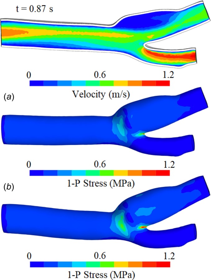
Fluid velocity magnitude and first principal stress on the outer surface of the arterial wall, at systole in the second cycle (t = 0.87 s). The arterial wall has heterogeneous properties in the media and adventitia, described by the fiber-reinforced constitutive model of [60]. In (a), the arterial wall is surrounded by subcutaneous adipose tissue, whose outer boundaries are fixed. In (b), the inlet and outlets are fixed and there is no surrounding external matrix.
3.4. Free Surface Wave.
This problem examined the ability of our formulation to model free-surface wave propagation by replicating the problem described by Hughes et al. [33]. This moving boundary problem modeled an experiment on solitary wave generation in a long channel, subjected to the force of gravity, with the wave generated by smoothly displacing the left end of the channel over a finite distance. Hughes et al. [33] examined two coarse meshes, and we replicated their second one here (see their Fig. 4), having two elements along the height and 161 elements along the length of the channel (Fig. 7) for a total of 972 nodes, 322 elements, and 4206 degrees-of-freedom. All other parameters and dimensions were kept the same as in that study, including the large time increment they used; the fluid was modeled as inviscid. In this problem, the top surface of the channel is the free surface on which we imposed a fluid-FSI traction. In addition to comparing febio results to those of Ref. [33], we used this problem to examine energy conservation as a function of ρ∞ in the generalized-α time integration scheme. The energy was calculated as the sum of the potential and kinetic energies of the fluid over the entire domain Ωf, plus the strain energy of the solid constituent of Ωf, though the latter was entirely negligible in this analysis. Results showed good agreement between febio (ρ∞ = 1) and the prior study [33] for the propagating wave profile at the midpoint and endpoint of the analysis (Fig. 7), and for the propagating wave velocity, which was in theory predicted to be 3.295 unit length/s, while in febio, it was calculated to be 3.290 unit length/s. Energy conservation was improved as ρ∞ was increased from 0 to 1 (Fig. 8), with the latter value demonstrating exact conservation, as expected from this time integration scheme.
3.5. Squeeze-Film Lubrication Between Flat Parallel Plates.
A squeeze-film lubrication problem was analyzed with febio, and the results were compared to an analytical solution of the Reynolds equation [59]. We looked specifically at a pair of parallel plates, squeezing a Newtonian lubricant along the direction normal to the plates. The analytical solution for the fluid pressure p and fluid shear stress τ acting on the top plate is given by
| (3.1) |
| (3.2) |
where x is the position with respect to the midpoint along the length of the plates, l is the plate length, X = x/l is the normalized position from the center of the plates (varying from −0.5 to 0.5), μ is the shear viscosity of the lubricant, h(t) is the lubricant film thickness, and w = dh/dt is the speed at which the top plate is approaching the bottom plate. The mass flow rate of fluid exiting the parallel plate domain, per unit depth, is .
The top plate was prescribed a normal velocity w while the bottom plate was fixed, with the fluid domain spanning the space between these two surfaces and no-slip conditions prescribed along the plates. The converged mesh had 30 elements along the film thickness, with a dual bias to capture boundary layers near both surfaces, and 450 elements uniformly distributed along the length of the plates, for a total of 27,962 nodes, 13,500 eight-node hexahedral elements, and 133,372 DOFs. The fluid material properties were set to K = 1013 Pa to enforce near-incompressibility (consistent with the given analytical solution), , and μ = 0.20889 Pa·s, using the properties of SAE 10W-40 engine oil at 20 °C.3
For our model, we chose l = 1 m and w = 90 μm/s. The analysis spanned 10 s (0 ≤ t ≤ 10) such that h(0) = 1 mm and h(10) = 0.1 mm, with the top plate displacing until the film thickness decreased to 0.1 mm. The time-step was set to Δt = 0.05 s. The peak fluid pressure, p(0, t), and the fluid shear stress at the final time, τ(x, 10), were compared with the above analytical solutions, showing good agreement (Fig. 9). The finite element solution for the pressure distribution p(x, t) at selected values of t was also compared to the analytical solution (Fig. 10). Good agreement was found between theory and febio for the whole range of x at all selected times.
Fig. 9.
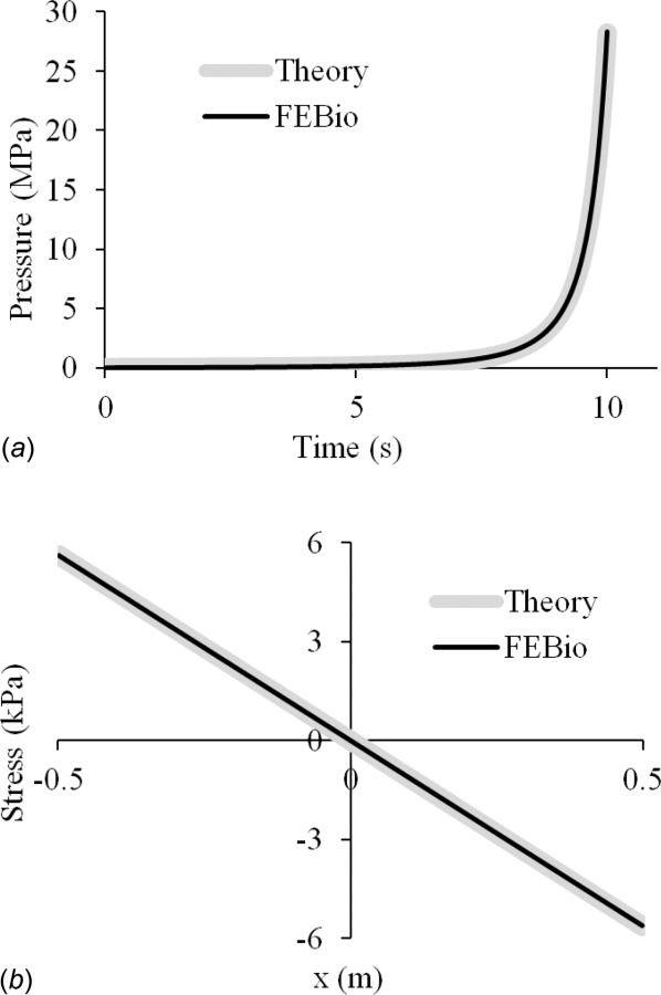
Squeeze-film lubrication between flat parallel plates: Comparison of febio results against the analytical solution of the Reynolds equation for (a) peak fluid pressure p(0, t) at the center of the plate, over the entire duration of the analysis (0 ≤ t ≤ 10 s), and (b) shear stress τ(x, 10) along the entire length of the plate at the final time
Mesh convergence was verified using progressively finer meshes, comparing the peak pressure at the final time point, p(0, 10), to the analytical solution as shown in Fig. 11. The relative error was shown to decrease at the rate of 1/(# of elements). We also verified that the mass flow rate of the oil being squeezed out of the plates matched the theoretical value, from the coarsest mesh density (0.049% error with 135 elements) to the finest (∼ 10−5% with 24,000 elements).
Fig. 11.
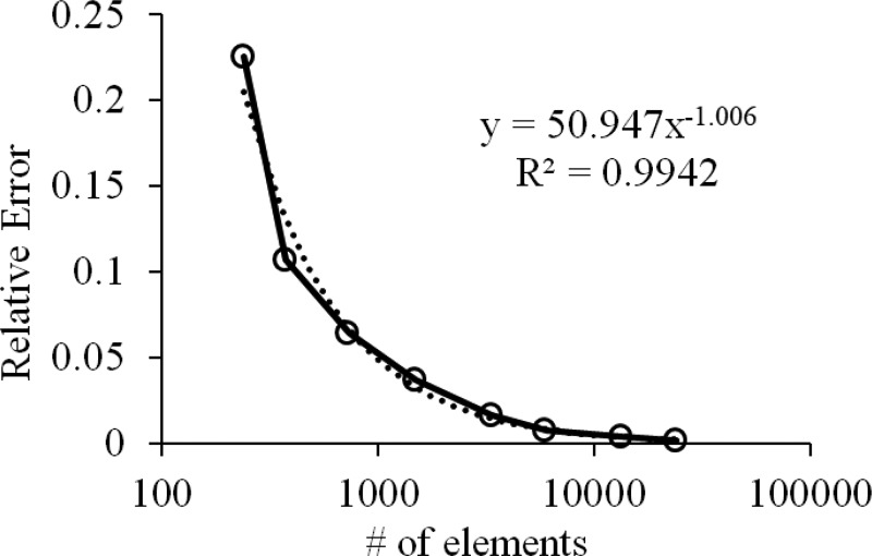
Mesh convergence study of squeeze-film lubrication between flat parallel plates, showing relative error of peak pressure at center of plate at t = 10 s as a function of the number of elements in the mesh
3.6. Carotid Bifurcation.
This problem analyzed a bifurcated carotid artery with thick arterial wall and non-Newtonian blood, surrounded by an adipose tissue matrix in one of the test cases, to illustrate the various features available in febio, such as fiber-reinforced constitutive models for the arterial wall and the ability to interface dissimilar meshes using a tied contact interface. The artery model was obtained from the GrabCAD community,4 similar to Ref. [29]. It was converted into the length unit of meter and meshed to include a boundary layer refinement using four-node tetrahedral elements, defining the fluid domain Ωf (163,771 elements). Blood was modeled as a Carreau fluid, using the parameters from Ref. [61], where viscosity is calculated as
| (3.3) |
where μ is viscosity, μ∞ is viscosity at infinite shear rate, μ0 is viscosity at zero shear rate, λ is the characteristic time, is the shear rate, and D is the rate of deformation (symmetric part of L), and n is the power index. Blood properties were set to , λ = 3.313 s, n = 0.3568, and K = 2.2 × 10⁹ Pa. The inlet () had a diameter of 6.28 mm and the two outlets ( and ) had respective diameters of 4.26 mm and 3.04 mm.
The arterial wall was created by extruding the outer surface of the artery twice, with the tunica media given a thickness of 0.33 mm and the tunica adventitia a thickness of 0.17 mm, for a total arterial wall thickness of 0.5 mm. These domains corresponded to and . The intima layer was not modeled explicitly, as it was assumed to provide a negligible contribution to the mechanical behavior of the arterial wall. Thus, the fluid–structure interface Γfs was located between Ωf and . All elements in the arterial wall consisted of six-node pentahedra (15,424 elements in each of and ).
The arterial wall constitutive model proposed by Holzapfel et al. was used [60], which models the tissue as a fiber reinforced composite with two fiber families. The material properties used here were obtained from Ref. [62] for the mean values of the human common carotid at the lower pressure range: c = 122,300 Pa, k1 = 24,700 Pa and k2 = 16.5 in the media; c = 59,600 Pa, k1 = 180,900 Pa, and k2 = 109.8 in the adventitia. The fiber families formed an angle of ±6.9 deg in the media and ±30.1 deg in the adventitia relative to the circumferential direction, which was determined at each element from the local direction of maximum principal curvature of the outer surface of each layer. In addition, we set ρs = 1000 kg/m3 for the dynamic response of the solid domains and , and used a bulk modulus of 108 Pa to enforce a nearly incompressible response.
For the fluid domain, an inlet velocity was prescribed on having a parabolic spatial profile, and an average value v0(t) whose time history is shown in Fig. 12, rising from a diastolic plateau of 0.10 m/s to a systolic maximum of 0.48 m/s in three consecutive cycles (Re = 165–800). A flow resistance boundary condition [29,63] was prescribed on both outlet faces and , with and a pressure offset p = 104 Pa. The inlet velocity was initially ramped up smoothly from zero to the diastolic value in 0.05 s, while the outlet pressure offset was ramped up smoothly over 0.25 s, to minimize the effects of pulse waves propagating in opposite directions from the inlet and outlets. Similarly, backflow and tangential stabilization [29,64] were prescribed on outlet faces and , with β = 1. (Also, see Supplemental Material on the ASME Digital Collection.) A fluid dilatation corresponding to a pressure p = 104 Pa was prescribed at the inlet rim to enhance the stability of the numerical solution, ramped up smoothly in 0.25 s. The interface Γfs was assumed to be no-slip and subjected to a fluid-FSI traction. Three different models were analyzed to explore the influence of various boundary conditions needed to restrain the motion of the solid domains and as the blood flowed under the conditions described above. In model A, the artery was embedded within a rectangular block (60 mm × 30 mm × 20 mm) of subcutaneous adipose tissue modeled as a compressible Neo-Hookean solid [57] with ρs = 1000 kg/m3, E = 1.17 × 10⁴ Pa, and ν = 0.3 [65]. The adipose tissue domain was created by Boolean subtraction of the artery from the block and meshed coarsely (77,314 four-node tetrahedral elements) relative to the arterial domains (), as shown in Fig. 13. The interface Γs between and was modeled as a tied contact interface [28]. The displacements of the walls of the adipose tissue were fixed. In model B, the artery was constrained by fixing the displacements of all nodes located on the inlet and outlet surfaces, inclusive of the fluid and solid domain boundaries. In model C, the artery was constrained by fixing only the displacements of nodes located on the inlet surface. Given these model configurations and boundary conditions, models A–C had a total of 273,127, 236,635 and 237,778 degrees-of-freedom, respectively. The models were set to run 1550 time steps with Δt = 1 ms.
Fig. 12.
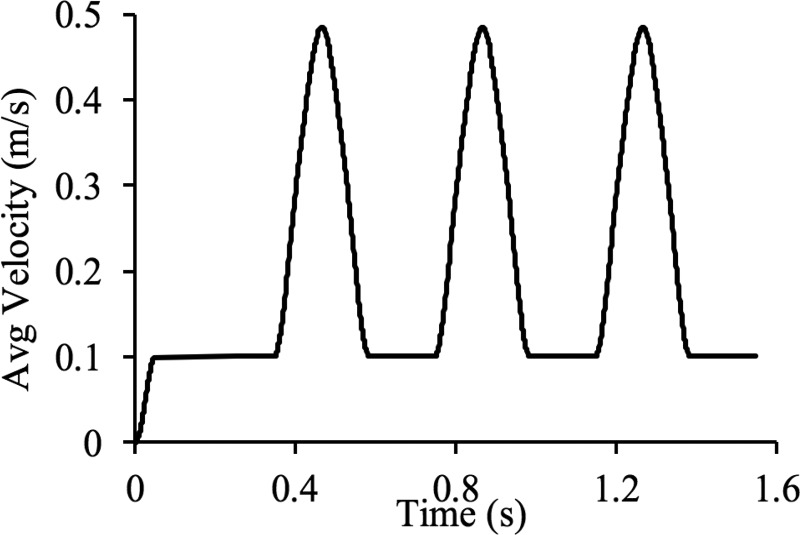
Prescribed average inlet velocity of bifurcated artery. Note that inlet is set to be parabolic, fully developed flow and the pulsatile flow runs for three cycles.
For model A, upon raising the fluid velocity from zero to the diastolic plateau of 0.10 m/s, the mass of fluid in domain Ωf increased by approximately 15% relative to the reference configuration at t = 0 due to inflation of the artery, thus providing a measure of the arterial wall compliance in response to the diastolic pressure (10.7 kPa in this model). At the peak systolic pressure (13.8 kPa), the fluid mass was approximately 17% higher than that of the reference configuration. The magnitude of the fluid velocity on a cross section and the first principal stress on the outer surface of the adventitia are displayed in Fig. 14 for model A at systole of the second cycle (t = 0.87 s, Fig. 12). Similarly, is displayed for model B, showing that the different methods of constraining the outer surfaces of the artery resulted in measurable quantitative differences in the stress response and arterial deformation. Despite those differences, it is interesting that the simpler constraints of model B did not produce drastically different outcomes than the more computationally expensive constraining method of model A, suggesting that it may represent a viable type of constraint in some applications. In contrast, the over-simplified constraint of model C produced a highly unstable response, as seen in Fig. 15, where the artery folded onto itself due to the strong effects of inertia forces as the blood rushed into the artery during the initial ramping of the inlet velocity (0 ≤ t ≤ 0.168 s). This result emphasizes that the modeling of fluid–structure interactions challenges users to develop better intuition for setting up physically realistic boundary conditions when the fluid and solid interact strongly. In addition to the above models used for exploring solid boundary constraints, we also examined the effect of simplifying the constitutive model of the arterial wall by neglecting the role of fibers and assuming homogeneous properties across the media and adventitia (model D), or by assuming that the arterial wall was rigid (model E, which is a standard CFD analysis with only a fluid domain). For model D, which used the same boundary conditions as model A, we used c = 97,000 Pa (volume weighted average of media and adventitia ground matrix properties of model A), ρs = 1000 kg/m3, and a bulk modulus of 5 × 10⁷ Pa to enforce near incompressibility. Model E used the same conditions on the boundaries of Ωf as model A.
Fig. 15.
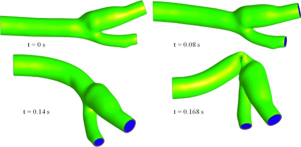
Inflation of the bifurcated artery for model C, where the inlet nodes are fixed, at different time points up until the time it failed (t = 0.168 s)
Overall, we found that the fluid maximum wall shear stress τmax achieved its largest value at systole, equal to 45.9 Pa in model A, 34.6 Pa in model D, and 46.0 Pa in model E. Also, the arterial wall responses in models A and D were significantly different from each other. In model D, the mass of fluid at diastole increased by 59% relative to the reference configuration, and at systole by 83%, confirming much greater compliance of the arterial wall in the absence of fiber reinforcement. The peak value of at systole was 1.52 MPa for the adventitia and 0.176 MPa for the media in model A, while it was 0.268 MPa for model D. Similarly, the peak value of the first principal stretch in the arterial wall was 1.14 for model A and 1.80 for model D. From these results, it is evident that the stiffening of the fibers in the Holzapfel model had a significant effect in the expansion and stress response of the arterial wall, primarily in the circumferential direction. As a result of the vascular wall stiffness, τmax was very similar in FSI model A and CFD model E, but significantly underestimated in the softer FSI model D.
In addition, we verified mass conservation in model A by examining the mass flow rate, , across the inlet and outlets, and the time rate of change of total fluid mass in the arterial lumen, as shown in Fig. 16. Taking the sum of all these mass flow rates produced an error less than 1.15% relative to the peak inlet mass flow rate across the entire analysis time, verifying that mass was sufficiently well conserved in this simulation.
Fig. 16.
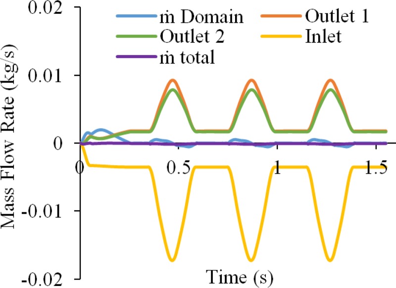
Results from bifurcated artery model A, showing the mass flow rates at inlet and outlet boundaries, the time rate of change of fluid mass in the fluid domain, and the sum of these measures (Total ), which should be zero according to the axiom of mass balance. The error observed in this analysis was less than 1.2% of the peak mass flow rate over the entire analysis.
3.7. Peristaltic Pump.
The dimensions of a peristaltic pump (Manostat Vera Model No. 72-315-000) were measured and used to model the main pump elements within febio. The pump (Fig. 17) consisted of a flexible tubing backed by a semicircular pump casing (radius = 31.17 mm) beginning and ending with linear segments to align the inlet and outlet portions of the tubing. Three rollers (diameter = 14.33 mm) were spaced equally apart on a circle with radius = 21.37 mm, initially offset by 2.1275 mm to the left of the semicircular casing center. The tubing (Tygon R-3603), which had an outer diameter of 4.7625 mm and an inner diameter of 1.3875 mm, was modeled as a compressible Neo-Hookean elastic solid () with and ν = 0.4, as obtained from the manufacturer's material specifications. The angular velocity ω of the rollers was varied in the analysis (2.202 ≤ ω ≤ 5.398 rad/s). Deionized water was used as the pumped fluid, with , and K = 2.2 × 10⁹ Pa in Ωf. To validate the febio model, the mass flow rate of the pump was obtained experimentally over the given range of ω; in the experiment, the tubing inlet was placed in a large diameter beaker of water of nearly constant height h = 2.6 cm, resulting in an inlet gage pressure of p = 255 Pa.
Fig. 17.
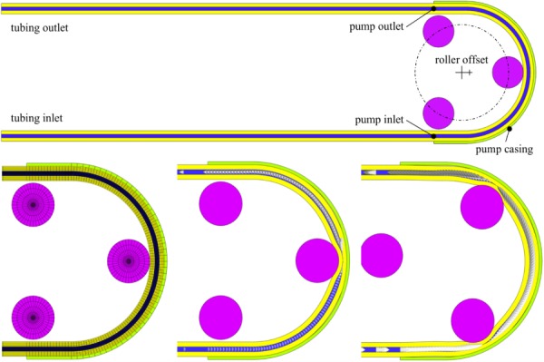
Mesh of the overall peristaltic pump (top). The pump mesh at t = 0 s (bottom left), pump with velocity arrows at t = 0.25 s (bottom center), and pump with velocity arrows at t = 0.5 s (bottom right).
The inner tube wall, Γfs, was assumed to be no-slip and was prescribed a fluid-FSI traction. The displacements of the tubing faces (Γf and Γs) at the pump inlet and outlet were clamped. The tubing was extended by 20 cm beyond the pump inlet and outlet, and the displacements of those ends were also fixed. The inlet pressure was set to 255 Pa and the outlet pressure was set to zero. The rollers and pump casing were modeled as rigid materials; the casing was modeled as a rigid body with fixed degrees-of-freedom and the rollers were combined into another rigid body whose angular velocity was set to ω, and all other degrees-of-freedom fixed. A frictionless elastic sliding contact interface [28] was prescribed between the tubing outer wall and the pump casing; a similar contact interface was prescribed between the tubing outer wall and the rollers such that the tubing could be compressed and constrained within the pump casing. Backflow and tangential stabilization schemes were prescribed for both the inlet and outlet boundaries of the tubing (β = 1). The flow was also constrained to remain normal to the inlet boundary.
The time steps were set to Δt = 2.5 ms for a total analysis time of 2.5 s, allowing for several roller passes along the tube. For the first 0.25 s, the roller offset was shifted rightward to increase occlusion of the tubing before rotation commenced. The febio model of the peristaltic pump assumed midplane symmetry for computational efficiency. Linear hexahedral and pentahedral elements were used for all domains. There were 43,910 nodes, 38,334 elements, and 273,021 degrees-of-freedom in this model.
Model results are presented at different times for ω = 3.842 rad/s in Fig. 17. These results show that the tubing was substantially occluded by the compression of each roller, to an inner diameter of 0.023 mm (98.3% occlusion) at the minimum location. Despite this substantial occlusion, the analysis proceeded without any difficulty. The comparison of the flow rate from the actual Manostat pump and the febio simulation is presented for several different angular velocities and two different levels of occlusion (94.9% and 98.3%) in Fig. 18. Experimental results produced a standard deviation less than 3.4% of the respective mean at each angular speed; therefore, standard deviation bars are not visible on the figure. Results from the two FSI simulation curves fell within 6% error from experimental data, providing good validation of the code. A sensitivity analysis showed that the mass flow rate was not significantly affected by changes in the tubing modulus by a factor of 1/2 or 2. Similarly, while results were somewhat sensitive to the inlet and outlet tubing configurations (e.g., bent or straight), this sensitivity diminished as the occlusion rate was increased. Effectively, occlusion of the tube was seen to have the most significant effect on predicted flow rate at different angular velocities; this parameter had to be adjusted in the model since it was not possible to extract its precise value from the measured dimensions of the pump, tubing, and rollers. Increasing the occlusion increased the flow rate for a given roller velocity; at these high occlusions, the flow rate was proportional to the roller velocity (Fig. 18). The current FSI implementation does not allow complete occlusion to take place. In the event that we can successfully model complete flow occlusion in the future, we would expect even closer agreement between the model and experiments.
Fig. 18.
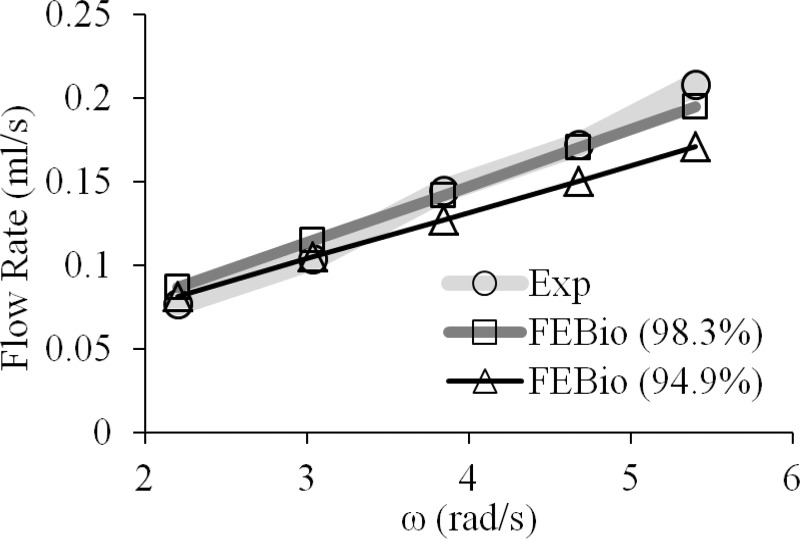
Comparison of the experimental flow rates and the flow rates obtained from febio for different amounts of occlusion
4. Discussion
The objective of this study was to implement a novel, general-purpose fluid–structure interaction solver in febio, an open-source finite element code specialized for applications in biomechanics and biophysics, combining the modeling capabilities already available in febio for solid mechanics and rigid body mechanics [20] with the recently developed CFD solver [29]. Two principal features of this novel formulation are the use of an isothermal compressible fluid formulation that satisfies the inf-sup condition without requiring additional stabilization terms, and the use of a mixture formulation to define material time derivatives that follow the motion of the mesh. These features considerably simplify the governing equations for FSI formulations in the ALE framework, as summarized in Eqs. (2.10), (2.11), (2.17), and (2.18). The simplicity of this formulation makes it easier for users of this open-source code to develop extensions of this framework for their specific needs. The formulation and implementation of this FSI solver enhance the multiphysics modeling capabilities relevant to the biomechanics and biophysics communities, since very few open-source FSI codes are currently available to meet their needs, and none of these provide febio's extensive library of customizable, nonlinear, anisotropic, hyperelastic, and viscoelastic solid materials needed to model cells or biological tissues that may also undergo remodeling and damage.
In the febio implementation, all constitutive models for solid and fluid materials are described in their own C++ class, derived from parent classes for solids and fluids, themselves derived from a parent class for all materials.5 The solid parent class includes functions for evaluating the solid stress and its tangent with respect to strain, at a given state of strain; the fluid parent class includes functions for evaluating the fluid pressure and its tangent with respect to dilatation, at a given state of dilatation, as well as functions for evaluating the viscous stress and its tangent with respect to the rate of deformation, at a given state of the rate of deformation. Therefore, the formulation and implementation of the FSI code remains very general, as it is not dependent on a specific set of constitutive relations, allowing the user to easily switch between materials, such as Newtonian and non-Newtonian fluids, compressible neo-Hookean, or uncoupled Mooney–Rivlin solid, or even create their own material model. This framework was demonstrated throughout the test problems presented in this study, where a variety of solid and fluid material constitutive relations were employed. Similarly, essential and natural boundary conditions are derived from general C++ classes in a similar manner, allowing users to define customized boundary conditions.
The fluid domain Ωf was modeled as a special case of a solid–fluid mixture whose solid constituent has zero mass; as reported in our previous study [29], the use of an isothermal compressible formulation for the fluid, with a physically based bulk modulus to enforce the right amount of compressibility, produced a set of governing equations that automatically satisfied the inf-sup condition, allowing us to use equal-order interpolation for all degrees-of-freedom, employing only the standard Galerkin method without requiring the incorporation of stabilization terms. As shown in Eq. (S5.14) available in the Supplemental Materials on the ASME Digital Collection, the stiffness matrix in this formulation is fully populated along the diagonal, leading to good convergence behavior even when assigning physically realistic values for the fluid bulk modulus.
The momentum balance of the fluid and solid constituents, and the kinematic constraint between the fluid velocity and dilatation, summarized in Eq. (2.15), were solved monolithically. Strong coupling between the fluid and solid domains resulted from choosing the velocity w of the fluid relative to the solid, instead of the fluid velocity vf, as nodal degrees-of-freedom. The relative fluid velocity was a logical choice for imposing no-slip conditions, w = 0, on deforming FSI interfaces. Though the fluid domain Ωf was modeled as a mixture of solid and fluid constituents, this special mixture was formulated with zero momentum exchange between the fluid and solid, and the solid constituent had zero mass density. However, to regularize the deformation of the mesh of Ωf, a negligible, but nonzero, solid elasticity needed to be imparted to the solid constituent. In the analyses reported in this study, we found that a compressible neo-Hookean elastic solid, with Poisson's ratio set to ν = 0 and Young's modulus E set to a negligibly small value, produced consistently good results even under very large deformations. Moreover, we found that a range of Young's moduli spanning several orders of magnitude, from 10−9 Pa up to 10−2 Pa in the problems presented above, did not significantly affect the results. In practice, the value of E should be selected to be a few orders of magnitude smaller than the elastic modulus of surrounding solid domains Ωs, when present. For moving boundary problems with no surrounding solid domains, the value of E should be selected such that its reduction by one order of magnitude causes no significant change in the solution.
Our FSI formulation was tested in different models that highlighted the different features available to the user and the efficacy of the code. The formulation was successfully verified against several benchmark problems found in Ref. [58], such as the 1D slip piston (Fig. 1), which tested the strong coupling between fluid and solid domains; the piston-cylinder problem (Fig. 3), which tested the response to moving boundaries; and the bubble inflation problem (Fig. 5), which tested both strong fluid–solid interactions in a problem with two fluid domains separated by a solid domain and large deformation in both fluid and solid domains. These validated models enhanced our confidence in the results of the carotid bifurcation problem, where similar responses occurred. We verified our code's ability to model a free surface wave by reproducing the results of Ref. [33] (Fig. 7); this problem was also used to verify that our implementation correctly satisfied energy conservation in the limit of ρ∞ = 1 (Fig. 8). Also, FSI formulations are notoriously difficult to verify against analytical solutions, since few such solutions exist. However, a useful category of engineering applications that offers analytical solutions for FSI is the field of lubrication. In this study, we showed that our formulation could successfully reproduce the analytical solution for squeeze-film lubrication between parallel plates, a moving boundary problem, obtained by solving the Reynolds equation (Figs. 9 and 10). We validated our code against experimental data by modeling an actual peristaltic pump in febio and comparing modeled and measured flow rates at multiple pump speeds (Fig. 17), taking advantage of sliding contact interfaces and rigid body mechanics in febio. In the context of FSI, where so few known solutions exist, the ability to reproduce this wide range of verification problems, supplemented by an experimental validation, affirms that our novel mixture-based formulation is robust and valid. Finally, we illustrated a biomechanics application of this new FSI solver by modeling blood flow in a bifurcated carotid artery using a range of useful features already available in febio: The blood was modeled as a non-Newtonian Carreau fluid, which shows that the material models for the fluid can extend beyond just Newtonian fluids. The thick arterial wall was modeled as an inhomogeneous elastic solid material (media and adventitia, Fig. 13(a)) using the fiber-reinforced, nearly incompressible tissue model of Holzapfel et al. [60]. We explored a variety of methods to constrain the motion of the outer arterial wall (Figs. 14 and 15), including one where the artery was surrounded by subcutaneous adipose tissue modeled with a coarser mesh and attached with a tied contact interface (Fig. 13(b)). In addition, we demonstrated the importance of choosing physically relevant boundary conditions, which can greatly affect the convergence and results in the model, as seen in the failed case without the surrounding adipose tissue, where only the inlet was constrained in Fig. 15. We also used a simpler arterial wall constitutive model to understand some of the ramifications of such choices in FSI analyses, and also performed a standard CFD analysis to examine the influence of using FSI on predictions of the fluid maximum shear stress. These illustrations were not meant to be exhaustive, as there are other interesting measures and phenomena that could be examined with FSI capabilities.
Fig. 7.
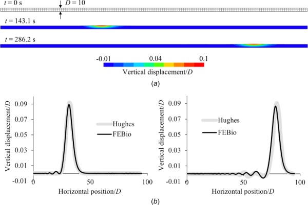
Free surface wave problem using an inviscid fluid, showing (a) the mesh at t = 0 and color contours of the normalized vertical displacement at the midpoint (t = 143.1 s) and endpoint (t = 286.2 s) of the analysis; and (b) a comparison of febio results and those of Hughes et al. [33] for the normalized vertical displacement versus normalized horizontal positions
Fig. 8.
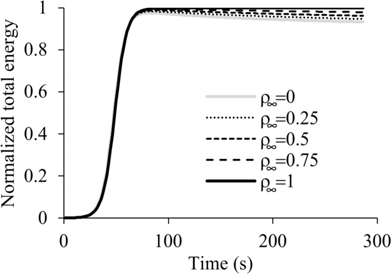
Free surface wave problem, showing the sum of potential and kinetic energies of the fluid over the entire domain Ωf for various values of ρ∞. Increasing values of ρ∞ demonstrate improved energy conservation, with ideal results achieved at ρ∞ = 1. The total energy is normalized to the steady-state value achieved under ideal conditions.
There are various measures that can be taken to improve convergence of a simulation with our FSI formulation. In most cases, we found that adding a boundary layer mesh near no-slip boundaries or other areas of sharp fluid velocity gradients significantly improved the convergence, compared to global mesh refinement. As a result, boundary layer refinement was done in all simulations where it was assumed to be necessary. Generally, this was only a requirement with the fluid domain, as the refinement of the solid domain could improve accuracy but appeared to have little effect on convergence in most cases. Additionally, analyses may benefit from smoothly ramping up prescribed displacements, velocities, or pressures from zero to the desired levels, as was done for example in surface wave propagation, the peristaltic pump, and the bifurcated carotid artery analyses, since a convenient (but nonphysical) sudden application of pressure or flow can send deformational waves propagating through the solid, sometimes causing accordion-like deformations that can lead to instabilities in FSI problems.
Since our FSI formulation did not explicitly require stabilization methods such as streamline-upwind/Petrov-Galerkin or Galerkin/least-squares, no special consideration was required for using linear versus higher order element interpolations. Thus, quadratic elements such as 20- or 27-node hexahedra, 15-node pentahedral, and 10- or 15-node tetrahedral currently available in febio may be used in FSI analyses using the current formulation. These element types can be used to create coarser meshes with less biased boundary layers. Furthermore, for our current FSI and CFD implementations, turbulence may be modeled using direct numerical simulation (DNS) only, which is highly demanding computationally, although future additions of turbulence models remain an option. Finally, as FSI problems are complex, the use of backflow and tangential stabilization may be required for outlet surfaces, and occasionally for inlet surfaces, as there may be temporary recirculation of fluid at these surfaces, which is not intuitively evident a priori. As a cautionary note, in some problems where sustained backflow at the outlet is physically expected, applying backflow stabilization may artificially lower the fluid velocity to the point where mass balance is not well conserved, since this boundary condition consists of applying a viscous traction opposing the flow. This undesired side effect, which only occurs in FSI (not CFD), is exacerbated by irregular meshes. Fortunately, it can be detected directly from the analysis results, and thus mitigated by using this type of boundary condition selectively (e.g., applied temporarily to stabilize the initiation of a dynamic analysis, but turned off once the desired flow conditions are achieved; and using more regular meshes when feasible).
For our FSI formulation, the generalized-α method was implemented successfully based on the work of Jansen et al. [43] and Bazilevs et al. [38]. It was implemented both for the FSI fluid domains Ωf and the surrounding solid domains Ωs. For these solid domains, we were also careful to employ an exact energy-momentum conservation scheme when using ρ∞ = 1 [66], though this specific feature was not relevant in the problems presented above. In some cases, such as the peristaltic pump or the bifurcated artery, ρ∞ = 0 produced the best result as it sufficiently dampened higher frequencies, where such damping had little effect on the accuracy of the solution. In those examples, using a higher value of ρ∞ did not sufficiently dampen the higher frequencies and led to an unstable solution, particularly when there was a rapid change in one or more of the prescribed boundary conditions. Overall, optimal behavior was problem-dependent and should be examined by the user.
The FSI formulation of this study represents only the first step in our broader strategy to develop a robust solver for applications in biomechanics and biophysics. Currently, our FSI formulation only interfaces fluid domains with solid domains (e.g., elastic, viscoelastic, and rigid solids), which are impermeable to the fluid. Since febio also includes modules for biphasic and multiphasic porous-permeable deformable domains, our future implementations of FSI will address transport of fluid across interfaces between fluid and biphasic/multiphasic domains. Since multiphasic domains also incorporate solute transport, future FSI (and CFD) implementations will also model solute transport and chemical reactions within the fluid domain. In addition, we plan to implement new features that will improve the functionality of the present FSI code. Currently, the solid domain surrounding the fluid domain cannot occlude the flow completely, as noted in the peristaltic pump example; therefore, a contact or collision detection algorithm for the solid domain with itself will be developed that can temporarily deactivate the fluid domain during flow occlusion. The development of tied fluid interfaces, which will allow for dissimilar meshes between fluid domains, or at the interface between fluid and solid domains, would also represent useful features. Large deformations in FSI analyses can lead to significant mesh distortions, which may degrade the numerical solution and limit the applications of this approach. Therefore, the incorporation of adaptive mesh regeneration techniques would represent a valuable addition to this formulation. In conjunction, implementing collision detection algorithms will improve the performance of our code particularly with thin solids experiencing large strains. Similarly, our monolithic FSI formulation must solve for seven degrees-of-freedom at each node in Ωf, and our existing quasi-Newton based solution method [29] becomes unwieldy with problems having more than ∼ 106 degrees-of-freedom. Therefore, iterative solvers specialized for our FSI formulation need to be developed and implemented to decrease memory requirements and increase computational efficiency.
Disclaimer
The content is solely the responsibility of the authors and does not necessarily represent the official views of the National Institutes of Health or the National Science Foundation.
Supplementary Material
Footnotes
Contributor Information
Jay J. Shim, Department of Mechanical Engineering, , Columbia University, , New York, NY 10027
Steve A. Maas, Department of Bioengineering, , University of Utah, , Salt Lake City, UT 84112
Jeffrey A. Weiss, Department of Bioengineering, , University of Utah, , Salt Lake City, UT 84112
Gerard A. Ateshian, Department of Mechanical Engineering, , Columbia University, , New York, NY 10027
Funding Data
Division of Graduate Education, U.S. National Science Foundation (Grant No. DGE-16-44869; Funder ID: 10.13039/100000082).
National Institute of General Medical Sciences, U.S. National Institutes of Health (Grant No. R01GM083925; Funder ID: 10.13039/100000057).
References
- [1]. Zhang, J. , 2000, “ Preconditioned Krylov Subspace Methods for Solving Nonsymmetric Matrices From CFD Applications,” Comput. Methods Appl. Mech. Eng., 189(3), pp. 825–840. 10.1016/S0045-7825(99)00345-X [DOI] [Google Scholar]
- [2]. Wolters, B. , Rutten, M. , Schurink, G. , Kose, U. , de Hart, J. , and van de Vosse, F. , 2005, “ A Patient-Specific Computational Model of Fluid–Structure Interaction in Abdominal Aortic Aneurysms,” Med. Eng. Phys., 27(10), pp. 871–883. 10.1016/j.medengphy.2005.06.008 [DOI] [PubMed] [Google Scholar]
- [3]. Krittian, S. , Janoske, U. , Oertel, H. , and Bohlke, T. , 2010, “ Partitioned Fluid–Solid Coupling for Cardiovascular Blood Flow,” Ann. Biomed. Eng., 38(4), pp. 1426–1441. 10.1007/s10439-009-9895-7 [DOI] [PubMed] [Google Scholar]
- [4]. Moghani, T. , Butler, J. P. , Lin, J. L.-W. , and Loring, S. H. , 2007, “ Finite Element Simulation of Elastohydrodynamic Lubrication of Soft Biological Tissues,” Comput. Struct., 85(11–14), pp. 1114–1120. 10.1016/j.compstruc.2006.08.026 [DOI] [PMC free article] [PubMed] [Google Scholar]
- [5]. Sweetman, B. , and Linninger, A. A. , 2011, “ Cerebrospinal Fluid Flow Dynamics in the Central Nervous System,” Ann. Biomed. Eng., 39(1), pp. 484–496. 10.1007/s10439-010-0141-0 [DOI] [PubMed] [Google Scholar]
- [6]. Sweetman, B. , Xenos, M. , Zitella, L. , and Linninger, A. A. , 2011, “ Three-Dimensional Computational Prediction of Cerebrospinal Fluid Flow in the Human Brain,” Comput. Biol. Med., 41(2), pp. 67–75. 10.1016/j.compbiomed.2010.12.001 [DOI] [PMC free article] [PubMed] [Google Scholar]
- [7]. Masoumi, N. , Framanzad, F. , Zamanian, B. , Seddighi, A. S. , Moosavi, M. H. , Najarian, S. , and Bastani, D. , 2013, “ 2D Computational Fluid Dynamic Modeling of Human Ventricle System Based on Fluid-Solid Interaction and Pulsatile Flow,” Basic Clin. Neurosci., 4(1), pp. 64–75.https://www.ncbi.nlm.nih.gov/pubmed/25337330 [PMC free article] [PubMed] [Google Scholar]
- [8]. Luo, H. , Mittal, R. , Zheng, X. , Bielamowicz, S. A. , Walsh, R. J. , and Hahn, J. K. , 2008, “ An Immersed-Boundary Method for Flow–Structure Interaction in Biological Systems With Application to Phonation,” J. Comput. Phys., 227(22), pp. 9303–9332. 10.1016/j.jcp.2008.05.001 [DOI] [PMC free article] [PubMed] [Google Scholar]
- [9]. Malve, M. , del Palomar, A. P. , Chandra, S. , Lopez-Villalobos, J. L. , Mena, A. , Finol, E. A. , Ginel, A. , and Doblare, M. , 2011, “ FSI Analysis of a Healthy and a Stenotic Human Trachea Under Impedance-Based Boundary Conditions,” ASME J. Biomech. Eng., 133(2), p. 021001. 10.1115/1.4003130 [DOI] [PubMed] [Google Scholar]
- [10]. Fung, Y. C. , and Liu, S. Q. , 1993, “ Elementary Mechanics of the Endothelium of Blood Vessels,” ASME J. Biomech. Eng., 115(1), p. 1. 10.1115/1.2895465 [DOI] [PubMed] [Google Scholar]
- [11]. Barakat, A. I. , 2001, “ A Model for Shear Stress-Induced Deformation of a Flow Sensor on the Surface of Vascular Endothelial Cells,” J. Theor. Biol., 210(2), pp. 221–236. 10.1006/jtbi.2001.2290 [DOI] [PubMed] [Google Scholar]
- [12]. Fritton, S. P. , and Weinbaum, S. , 2009, “ Fluid and Solute Transport in Bone: Flow-Induced Mechanotransduction,” Annu. Rev. Fluid Mech., 41(1), pp. 347–374. 10.1146/annurev.fluid.010908.165136 [DOI] [PMC free article] [PubMed] [Google Scholar]
- [13]. Kwon, R. Y. , and Frangos, J. A. , 2010, “ Quantification of Lacunar–Canalicular Interstitial Fluid Flow Through Computational Modeling of Fluorescence Recovery After Photobleaching,” Cell. Mol. Bioeng., 3(3), pp. 296–306. 10.1007/s12195-010-0129-8 [DOI] [PMC free article] [PubMed] [Google Scholar]
- [14]. Scheiner, S. , Pivonka, P. , and Hellmich, C. , 2016, “ Poromicromechanics Reveals That Physiological Bone Strains Induce Osteocyte-Stimulating Lacunar Pressure,” Biomech. Model. Mechanobiol., 15(1), pp. 9–28. 10.1007/s10237-015-0704-y [DOI] [PMC free article] [PubMed] [Google Scholar]
- [15]. Fiore, G. B. , Redaelli, A. , Guadagni, G. , Inzoli, F. , and Fumero, R. , 2002, “ Development of a New Disposable Pulsatile Pump for Cardiopulmonary Bypass: Computational Fluid-Dynamic Design and In Vitro Tests,” ASAIO J., 48(3), pp. 260–267. 10.1097/00002480-200205000-00011 [DOI] [PubMed] [Google Scholar]
- [16]. Vo, G. D. , Brindle, E. , and Heys, J. , 2010, “ An Experimentally Validated Immersed Boundary Model of Fluid–Biofilm Interaction,” Water Sci. Technol., 61(12), p. 3033. 10.2166/wst.2010.213 [DOI] [PubMed] [Google Scholar]
- [17]. Malve, M. , del Palomar, A. P. , Chandra, S. , Lopez-Villalobos, J. L. , Finol, E. A. , Ginel, A. , and Doblare, M. , 2011, “ FSI Analysis of a Human Trachea Before and After Prosthesis Implantation,” ASME J. Biomech. Eng., 133(7), p. 071003. 10.1115/1.4004315 [DOI] [PubMed] [Google Scholar]
- [18]. Avanzini, A. , and Battini, D. , 2014, “ Structural Analysis of a Stented Pericardial Heart Valve With Leaflets Mounted Externally,” Proc. Inst. Mech. Eng., Part H, 228(10), pp. 985–995. 10.1177/0954411914552309 [DOI] [PubMed] [Google Scholar]
- [19]. Maas, S. A. , Ateshian, G. A. , and Weiss, J. A. , 2017, “ Febio: History and Advances,” Annu. Rev. Biomed. Eng., 19, pp. 279–299. 10.1146/annurev-bioeng-071516-044738 [DOI] [PMC free article] [PubMed] [Google Scholar]
- [20]. Maas, S. A. , Ellis, B. J. , Ateshian, G. A. , and Weiss, J. A. , 2012, “ FEBio: Finite Elements for Biomechanics,” ASME J. Biomech. Eng., 134(1), p. 011005. 10.1115/1.4005694 [DOI] [PMC free article] [PubMed] [Google Scholar]
- [21]. Ateshian, G. A. , Nims, R. J. , Maas, S. , and Weiss, J. A. , 2014, “ Computational Modeling of Chemical Reactions and Interstitial Growth and Remodeling Involving Charged Solutes and Solid-Bound Molecules,” Biomech. Model. Mechanobiol., 13(5), pp. 1105–1120. 10.1007/s10237-014-0560-1 [DOI] [PMC free article] [PubMed] [Google Scholar]
- [22]. Nims, R. J. , Durney, K. M. , Cigan, A. D. , Dusséaux, A. , Hung, C. T. , and Ateshian, G. A. , 2016, “ Continuum Theory of Fibrous Tissue Damage Mechanics Using Bond Kinetics: Application to Cartilage Tissue Engineering,” Interface Focus, 6(1), p. 20150063. 10.1098/rsfs.2015.0063 [DOI] [PMC free article] [PubMed] [Google Scholar]
- [23]. Maas, S. A. , Erdemir, A. , Halloran, J. P. , and Weiss, J. A. , 2016, “ A General Framework for Application of Prestrain to Computational Models of Biological Materials,” J. Mech. Behav. Biomed. Mater., 61, pp. 499–510. 10.1016/j.jmbbm.2016.04.012 [DOI] [PMC free article] [PubMed] [Google Scholar]
- [24]. Ateshian, G. A. , 2015, “ Viscoelasticity Using Reactive Constrained Solid Mixtures,” J. Biomech., 48(6), pp. 941–947. 10.1016/j.jbiomech.2015.02.019 [DOI] [PMC free article] [PubMed] [Google Scholar]
- [25]. Ateshian, G. A. , Maas, S. , and Weiss, J. A. , 2013, “ Multiphasic Finite Element Framework for Modeling Hydrated Mixtures With Multiple Neutral and Charged Solutes,” ASME J. Biomech. Eng., 135(11), p. 111001. 10.1115/1.4024823 [DOI] [PMC free article] [PubMed] [Google Scholar]
- [26]. Ateshian, G. A. , Maas, S. , and Weiss, J. A. , 2010, “ Finite Element Algorithm for Frictionless Contact of Porous Permeable Media Under Finite Deformation and Sliding,” ASME J. Biomech. Eng., 132(6), p. 061006. 10.1115/1.4001034 [DOI] [PMC free article] [PubMed] [Google Scholar]
- [27]. Ateshian, G. A. , Maas, S. , and Weiss, J. A. , 2012, “ Solute Transport Across a Contact Interface in Deformable Porous Media,” J. Biomech., 45(6), pp. 1023–1027. 10.1016/j.jbiomech.2012.01.003 [DOI] [PMC free article] [PubMed] [Google Scholar]
- [28]. Zimmerman, B. K. , and Ateshian, G. A. , 2018, “ A Facet-to-Facet Finite Element Algorithm for Large Deformation Frictional Contact in Febio,” ASME J. Biomech. Eng., 140(8), p. 081013. [DOI] [PMC free article] [PubMed] [Google Scholar]
- [29]. Ateshian, G. A. , Shim, J. J. , Maas, S. A. , and Weiss, J. A. , 2018, “ Finite Element Framework for Computational Fluid Dynamics in FEBio,” ASME J. Biomech. Eng., 140(2), p. 021001. 10.1115/1.4038716 [DOI] [PMC free article] [PubMed] [Google Scholar]
- [30]. Tian, F.-B. , Dai, H. , Luo, H. , Doyle, J. F. , and Rousseau, B. , 2014, “ Fluid–Structure Interaction Involving Large Deformations: 3D Simulations and Applications to Biological Systems,” J. Comput. Phys., 258, pp. 451–469. 10.1016/j.jcp.2013.10.047 [DOI] [PMC free article] [PubMed] [Google Scholar]
- [31]. Peskin, C. S. , 1972, “ Flow Patterns Around Heart Valves: A Numerical Method,” J. Comput. Phys., 10(2), pp. 252–271. 10.1016/0021-9991(72)90065-4 [DOI] [Google Scholar]
- [32]. Peskin, C. S. , 1977, “ Numerical Analysis of Blood Flow in the Heart,” J. Comput. Phys., 25(3), pp. 220–252. 10.1016/0021-9991(77)90100-0 [DOI] [Google Scholar]
- [33]. Hughes, T. J. , Liu, W. K. , and Zimmermann, T. K. , 1981, “ Lagrangian-Eulerian Finite Element Formulation for Incompressible Viscous Flows,” Comput. Methods Appl. Mech. Eng., 29(3), pp. 329–349. 10.1016/0045-7825(81)90049-9 [DOI] [Google Scholar]
- [34]. Donea, J. , Giuliani, S. , and Halleux, J. , 1982, “ An Arbitrary Lagrangian-Eulerian Finite Element Method for Transient Dynamic Fluid-Structure Interactions,” Comput. Methods Appl. Mech. Eng., 33(1–3), pp. 689–723. 10.1016/0045-7825(82)90128-1 [DOI] [Google Scholar]
- [35]. Tezduyar, T. , 1991, “ Stabilized Finite Element Formulations for Incompressible Flow Computations,” Advances in Applied Mechanics, Elsevier, San Diego, CA, pp. 1–44. [Google Scholar]
- [36]. Tezduyar, T. , Behr, M. , Mittal, S. , and Liou, J. , 1992, “ A New Strategy for Finite Element Computations Involving Moving Boundaries and Interfaces—The Deforming-Spatial-Domain/Space-Time Procedure—II: Computation of Free-Surface Flows, Two-Liquid Flows, and Flows With Drifting Cylinders,” Comput. Methods Appl. Mech. Eng., 94(3), pp. 353–371. 10.1016/0045-7825(92)90060-W [DOI] [Google Scholar]
- [37]. Tezduyar, T. E. , Sathe, S. , Keedy, R. , and Stein, K. , 2006, “ Space–Time Finite Element Techniques for Computation of Fluid–Structure Interactions,” Comput. Methods Appl. Mech. Eng., 195(17–18), pp. 2002–2027. 10.1016/j.cma.2004.09.014 [DOI] [Google Scholar]
- [38]. Bazilevs, Y. , Calo, V. M. , Hughes, T. J. R. , and Zhang, Y. , 2008, “ Isogeometric Fluid-Structure Interaction: Theory, Algorithms, and Computations,” Comput. Mech., 43(1), pp. 3–37. 10.1007/s00466-008-0315-x [DOI] [Google Scholar]
- [39]. Brezzi, F. , and Bathe, K.-J. , 1990, “ A Discourse on the Stability Conditions for Mixed Finite Element Formulations,” Comput. Methods Appl. Mech. Eng., 82(1–3), pp. 27–57. 10.1016/0045-7825(90)90157-H [DOI] [Google Scholar]
- [40]. Reddy, J. N. , and Gartling, D. , 2000, The Finite Element Method in Heat Transfer and Fluid Dynamics (Computational Mechanics and Applied Analysis), 2nd ed., CRC Press, Boca Raton, FL [Google Scholar]
- [41]. Brooks, A. N. , and Hughes, T. J. , 1982, “ Streamline Upwind/Petrov-Galerkin Formulations for Convection Dominated Flows With Particular Emphasis on the Incompressible Navier-Stokes Equations,” Comput. Methods Appl. Mech. Eng., 32(1–3), pp. 199–259. 10.1016/0045-7825(82)90071-8 [DOI] [Google Scholar]
- [42]. Chung, J. , and Hulbert, G. M. , 1993, “ A Time Integration Algorithm for Structural Dynamics With Improved Numerical Dissipation: The Generalized-α Method,” ASME J. Appl. Mech., 60(2), p. 371. 10.1115/1.2900803 [DOI] [Google Scholar]
- [43]. Jansen, K. E. , Whiting, C. H. , and Hulbert, G. M. , 2000, “ A Generalized-α Method for Integrating the Filtered Navier–Stokes Equations With a Stabilized Finite Element Method,” Comput. Methods Appl. Mech. Eng., 190(3–4), pp. 305–319. 10.1016/S0045-7825(00)00203-6 [DOI] [Google Scholar]
- [44]. Truesdell, C. , and Toupin, R. , 1960, “ The Classical Field Theories,” Encyclopedia of Physics, Vol. III/1, Springer-Verlag, Berlin. [Google Scholar]
- [45]. Green, A. E. , and Naghdi, P. M. , 1969, “ On Basic Equations for Mixtures,” Q. J. Mech. Appl. Math., 22(4), pp. 427–438. 10.1093/qjmam/22.4.427 [DOI] [Google Scholar]
- [46]. Bowen, R. M. , 1976, “ Theory of Mixtures,” Continuum Physics, Academic Press, New York. [Google Scholar]
- [47]. Bedford, A. , and Drumheller, D. S. , 1983, “ Theories of Immiscible and Structured Mixtures,” Int. J. Eng. Sci., 21(8), pp. 863–960. 10.1016/0020-7225(83)90071-X [DOI] [Google Scholar]
- [48]. Mow, V. C. , Kuei, S. C. , Lai, W. M. , and Armstrong, C. G. , 1980, “ Biphasic Creep and Stress Relaxation of Articular Cartilage in Compression? Theory and Experiments,” ASME J. Biomech. Eng., 102(1), pp. 73–84. 10.1115/1.3138202 [DOI] [PubMed] [Google Scholar]
- [49]. Oomens, C. W. , van Campen, D. H. , and Grootenboer, H. J. , 1987, “ A Mixture Approach to the Mechanics of Skin,” J. Biomech., 20(9), pp. 877–885. 10.1016/0021-9290(87)90147-3 [DOI] [PubMed] [Google Scholar]
- [50]. Lai, W. M. , Hou, J. S. , and Mow, V. C. , 1991, “ A Triphasic Theory for the Swelling and Deformation Behaviors of Articular Cartilage,” ASME J. Biomech. Eng., 113(3), pp. 245–258. 10.1115/1.2894880 [DOI] [PubMed] [Google Scholar]
- [51]. Huyghe, J. M. , and Janssen, J. , 1997, “ Quadriphasic Mechanics of Swelling Incompressible Porous Media,” Int. J. Eng. Sci., 35(8), pp. 793–802. 10.1016/S0020-7225(96)00119-X [DOI] [Google Scholar]
- [52]. Humphrey, J. D. , and Rajagopal, K. R. , 2003, “ A Constrained Mixture Model for Arterial Adaptations to a Sustained Step Change in Blood Flow,” Biomech. Model. Mechanobiol., 2(2), pp. 109–126. 10.1007/s10237-003-0033-4 [DOI] [PubMed] [Google Scholar]
- [53]. Ateshian, G. A. , and Ricken, T. , 2010, “ Multigenerational Interstitial Growth of Biological Tissues,” Biomech. Model. Mechanobiol., 9(6), pp. 689–702. 10.1007/s10237-010-0205-y [DOI] [PMC free article] [PubMed] [Google Scholar]
- [54]. Ateshian, G. A. , Albro, M. B. , Maas, S. , and Weiss, J. A. , 2011, “ Finite Element Implementation of Mechanochemical Phenomena in Neutral Deformable Porous Media Under Finite Deformation,” ASME J. Biomech. Eng., 133(8), p. 081005. 10.1115/1.4004810 [DOI] [PMC free article] [PubMed] [Google Scholar]
- [55]. Bowen, R. M. , 1982, “ Compressible Porous Media Models by Use of the Theory of Mixtures,” Int. J. Eng. Sci., 20(6), pp. 697–735. 10.1016/0020-7225(82)90082-9 [DOI] [Google Scholar]
- [56]. Donea, J. , and Huerta, A. , 2003, Finite Element Methods for Flow Problems, Wiley, Somerset, NJ. [Google Scholar]
- [57]. Bonet, D. J. , and Wood, D. R. D. , 2008, Nonlinear Continuum Mechanics for Finite Element Analysis, Cambridge University Press, Cambridge, UK. [Google Scholar]
- [58]. Bathe, K.-J. , and Ledezma, G. A. , 2007, “ Benchmark Problems for Incompressible Fluid Flows With Structural Interactions,” Comput. Struct., 85(11–14), pp. 628–644. 10.1016/j.compstruc.2007.01.025 [DOI] [Google Scholar]
- [59]. Hamrock, B. J. , 1994, Fundamentals of Fluid Film Lubrication, McGraw-Hill Companies, New York. [Google Scholar]
- [60]. Holzapfel, G. A. , Gasser, T. C. , and Ogden, R. W. , 2000, “ A New Constitutive Framework for Arterial Wall Mechanics and a Comparative Study of Material Models,” J. Elast., 61(1/3), pp. 1–48. 10.1023/A:1010835316564 [DOI] [Google Scholar]
- [61]. Cho, Y. I. , and Kensey, K. R. , 1991, “ Effects of the Non-Newtonian Viscosity of Blood on Flows in a Diseased Arterial Vessel—Part 1: Steady Flows,” Biorheology, 28(3–4), pp. 241–262. 10.3233/BIR-1991-283-415 [DOI] [PubMed] [Google Scholar]
- [62]. Sommer, G. , and Holzapfel, G. A. , 2012, “ 3D Constitutive Modeling of the Biaxial Mechanical Response of Intact and Layer-Dissected Human Carotid Arteries,” J. Mech. Behav. Biomed. Mater., 5(1), pp. 116–128. 10.1016/j.jmbbm.2011.08.013 [DOI] [PubMed] [Google Scholar]
- [63]. Vignon-Clementel, I. E. , Figueroa, C. A. , Jansen, K. E. , and Taylor, C. A. , 2006, “ Outflow Boundary Conditions for Three-Dimensional Finite Element Modeling of Blood Flow and Pressure in Arteries,” Comput. Methods Appl. Mech. Eng., 195(29–32), pp. 3776–3796. 10.1016/j.cma.2005.04.014 [DOI] [Google Scholar]
- [64]. Moghadam, M. E. , Bazilevs, Y. , Hsia, T.-Y. , Vignon-Clementel, I. E. , and Marsden, A. L. , 2011, “ A Comparison of Outlet Boundary Treatments for Prevention of Backflow Divergence With Relevance to Blood Flow Simulations,” Comput. Mech., 48(3), pp. 277–291. 10.1007/s00466-011-0599-0 [DOI] [Google Scholar]
- [65]. Alkhouli, N. , Mansfield, J. , Green, E. , Bell, J. , Knight, B. , Liversedge, N. , Tham, J. C. , Welbourn, R. , Shore, A. C. , Kos, K. , and Winlove, C. P. , 2013, “ The Mechanical Properties of Human Adipose Tissues and Their Relationships to the Structure and Composition of the Extracellular Matrix,” Am. J. Physiol.-Endocrinol. Metab., 305(12), pp. E1427–E1435. 10.1152/ajpendo.00111.2013 [DOI] [PubMed] [Google Scholar]
- [66]. Gonzalez, O. , 2000, “ Exact Energy and Momentum Conserving Algorithms for General Models in Nonlinear Elasticity,” Comput. Methods Appl. Mech. Eng., 190(13–14), pp. 1763–1783. 10.1016/S0045-7825(00)00189-4 [DOI] [Google Scholar]
Associated Data
This section collects any data citations, data availability statements, or supplementary materials included in this article.


