Abstract
Rational design and controllable synthesis of silica nanomaterials bearing unique physicochemical properties is becoming increasingly important for a variety of biomedical applications from imaging to drug delivery. Microfluidics has recently emerged as a promising platform for nanomaterial synthesis, providing precise control over particle size, shape, porosity, and structure compared to conventional batch synthesis approaches. This review summarizes microfluidic approaches for the synthesis of silica materials as well as the design, fabrication and the emerging roles in the development of new classes of functional biomaterials. We highlight the unprecedented opportunities of microreactors in biomaterial synthesis, assess the recent progress of continuous and discrete microreactors and the associated biomedical applications of silica materials. Finally, we discuss the challenges arising from the intrinsic properties of microfluidic reactors for inspiring future research in this field.
Graphical Abstract
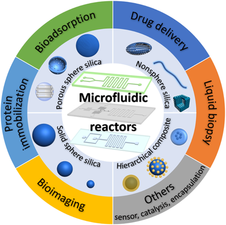
Comprehensive overview of microfluidics-enabled controllable synthesis and emerging bioapplications of silica micro-/nanomaterials
1. Introduction
Since Stöber first introduced solid silica micro-/nanoparticles through the hydrolysis and condensation process of silicates under basic conditions in 1968,1 the past several decades have witnessed an explosive growth in the synthesis of silica materials especially from the discovery of porous silica particles in 1992.2 Solid and porous silica materials with advanced features, such as good biocompatibility, high thermal and mechanical stability, and ease of surface functionalization, show great promises in numerous biological applications ranging from bioimaging, biosensor, drug delivery, to disease theranostics.3–8 Accompanying with the use of silica materials spreading from applications requiring large bulk quantities to niche biological applications, the requirements on the physicochemical properties of particulates including size, shape, porosity, and structure are becoming increasingly important and stringent.9–11
Over the years, a number of different synthetic methods based on conventional batch reactors have been developed for producing silica materials. Many of these methods, however, always suffer from issues of uniformity, yield, and batch-to-batch reproducibility arising from inadequate reaction control.5,12–14 The advent of microfluidics in the 1990s opened a new realm of possibilities for chemical engineering in the confined space on a micrometer scale.15–21 Microfluidics systems enables controllable and precise manipulation of process parameters (e.g. flow rate, residence time, temperature, and pressure), which provides a powerful platform for continuous, scalable, and reproducible production of micro-/nanomaterials with unprecedented control over their size, shape, porosity, and structure properties. To date, microfluidic techniques have already fully demonstrated their remarkable capacity in the rational design and controllable synthesis of polymer,22–26 quantum dots,27,28 and metallic materials.29,30 For the synthesis of silica materials through microfluidic reactors, although it is still in the preliminary stage, there have already been a range of important developments and breakthroughs by researchers including our group.
This review first discusses the recent progress of microfluidics for the synthesis and bioapplications of silica materials. Specifically, it is organized as follows: firstly, we highlight the unprecedented opportunities of microfluidic reactors in the rational design and controllable synthesis of silica biomaterials compared with conventional batch reactors; secondly, we summarize recent achievements of microfluidics-enabled synthesis of solid and porous silica materials from continuous and discrete microreactors; then, established bioapplications of silica materials from microreactors in the areas of bioimaging, protein immobilization, bioadsorption, drug delivery, and liquid biopsy are presented; finally, we identify the challenges of microfluidics in silica biomaterials synthesis and propose future perspectives in this research field.
2. Beyond batch reactor: why microreactor matters
2.1. Microfluidic design parameters
Microreactors build upon microfluidics technology, which studies the science and technology of systems that manipulate micro- or nanoliter fluids and exploit their unique behaviors at microscale.18 The direct advantage of scaling down in dimensions is the high surface-to-volume ratio, which provides rapid heat and mass transfer in microreactors. Surface forces such as viscous forces dominate over inertial forces in microreactors. The ratio of the two is described by the Reynolds number (Re), which is a dimensionless number often used to estimate if the flow in microreactors is laminar or turbulent.31 The expression for the Reynolds number is:
where ρ is the density of the fluids (kg/m3), U is the average velocity of the fluids (m/s), L is the characteristic length of the microchannel (m), and μ is the dynamic viscosity of the fluids (Pa·s). The flow in microreactors is almost always laminar due to the microscale. This makes the flow very easily predictable: at a given point, velocity is constant. The governing equations of fluid dynamics in microreactors are Navier-Stokes equations31:
where is the velocity field, p is the pressure field, and is the force field. The Navier-Stokes equations can be simplified by assuming low Reynolds number, and incompressible and fully-developed Newtonian fluids. With non-slip boundary conditions, parabolic velocity profile can be obtained by solving the simplified equations. While laminar flow allows for more controllable reactions in microreactors, it causes diffusion limited mixing of reagents. This can be addressed by designing passive or active mixing modules based on strategies such as chaotic advection or electrokinetics.32 Design of microreactors for advanced mixing performance is guided by the Péclet number (Pe)31:
where U is the average velocity of the fluids (m/s), L is the characteristic length of the microchannel (m), and D is the diffusion coefficient (m2/s). The Péclet number compares the rate of advection (or transport by the fluids) to that of diffusion across the fluids. The scale of molecular diffusion coefficient is 10−10~10−11 (m2/s),33 the dimension of microchannels is 10−6~10−4(m), and a typical velocity in microchannels is ~1(m/s), so the Péclet number in microreactors is relatively large, and the effect of diffusion-induced mixing could even be neglected in some cases. For improved mixing, one strategy is to increase the length of microchannels by adding long winding channels.
2.2. Pressure-driven microreactors: laminar flow and discrete flow
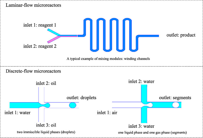
Compared to conventional batch-mode reactors, microreactors have many superior properties: rapid heat and mass transfer ensures fast kinetic reactions, low volume of fluids brings low consumption of reagents and low cost, and predictable laminar flow offers controllable synthesis process.34 There are five groups of major microfluidic systems based on main liquid propulsion principle: capillary-based, pressure driven, centrifugal, electrokinetic, and acoustic microfluidic platforms.35 Pressure-driven microfluidic platforms have been chosen for chemical synthesis as they are easier to control and more flexible to design, not requiring any external fields. In this review, we mainly focus on pressure-driven microreactors unless otherwise stated. Pressure-driven microreactors can be further categorized into two main groups: single-phase continuous laminar flow and multi-phase discrete flow. As shown in Figure 1, continuous laminar-flow microreactors are simply designed with multiple inlets for different reagents, an outlet for final reaction products and a mixing module to improve diffusion-limited mixing in microreactors. A typical example of mixing modules is winding channels.32 Discrete flow microreactors include both liquid droplets and gas segments. Droplets microreactors involve two immiscible liquid phases such as water (reagent fluid) and silicone oil (carrier fluid) to generate droplets.36 The compartmentalization provides an enclosed chamber where reagents can mix dramatically with each other. Droplets formation requires specific “nozzle” design such as Y-shaped, T-shaped, or cross-shaped geometries.37 The size of the droplets controls the size, morphology and monodispersity of final reaction products. Another common type of discrete flow microreactors uses gas phase to separate “segments” of reagents. This can be used to avoid any contaminations introduced by carrier fluids.
Figure 1.
Pressure-driven microreactors categorized into two main groups: continuous laminar-flow and discrete segmented-flow microreactors.
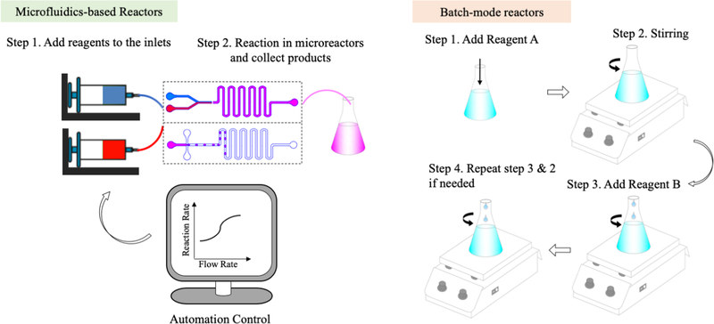
The workflows of both microreactors and batch-mode reactors are provided in Figure 2. Operation in microreactors is simple and convenient: add reagents into syringes that connect to the inlets of microreactors, set flow rate for each inlet flow, determine target volume, wait until reaction is done, and collect products at the outlet. During the procedure, manual operation is only required at the beginning and the very end. The process is programmable and automatic. Reaction rate can be tuned by changing the flow rate of reagents and by adjusting the reaction time. The geometry design of microreactors also offers flexibility towards the synthesis. In comparison, the procedure of conventional batch-mode reactors is very complicated, non-automatic, and not programmable. Each step demands human labor and careful operations such as dropwise addition of reagents. For a reaction that takes hours, watching over the whole process and adding different reagents at certain time is required, making the process extremely troublesome and time-consuming. Moreover, mixing of reagents relies on magnetic or mechanic stirring, which is not as efficient or complete as that at microscale. Reaction rate can only be affected by limited stirring rate. The conventional batch-mode reactors lack control over the synthesis process.
Figure 2.
Workflow of microfluidics-based reactors and batch-mode reactors (image not to scale).
A comparison between microreactors (both laminar-flow and segmented-flow microreactors) and conventional batch-mode reactors was summarized in Table 1.38 While batch-mode reactors require extra labor and effort, microreactors are very convenient to operate. In microreactors, we can easily adjust parameters for the reaction including the geometry design of microreactors and flow rate. In batch-mode reactors, we can only change the stirring rate during the reaction, which does not really give us any control. Compared to batch-mode reactors, precise control over each step including seeding, growth and reaction cessation in microreactors is possible. This gives us high uniformity and reproducibility in microreactors. The precise control can also be made automatic when programmable equipment is hooked up to syringe pumps for pressure-driven microreactors. When talking about efficiency, batch-mode reactors can produce large quantity of products and microreactors seem to lack this advantage due to their small size. However, considering the overall time required for reaction in both reactors, the productivity in microreactors is comparable to that in batch-mode reactors. Parallel processing can also be used to scale out the production in microreactors, which makes them even more efficient and low cost. For reactions involving expensive materials, the very low consumption of reagents by microreactors stands them out compared to batch-mode reactors. With an enclosed environment, microreactors are also suitable for reactions under very harsh conditions. With all the benefits, microreactors are perfect candidates to develop new materials or to screen drugs for research or even industrial purpose.
Table 1.
The comparison between microfluidic reactors and batch reactors.
| Microfluidic Reactors | Macroscopic Batch Reactors | ||
|---|---|---|---|
| Laminar flow | Segmented flow | ||
| Chip-scale operations | Yes | Yes | No |
| Tunable parameters | Yes, the design of microfluidic reactors and the adjustable flow rate provide flexible reactions | No, the only adjustable parameter may be the stirring rate during the reaction | |
| Fast reaction | Yes, generally takes seconds or less | No, usually takes hours or days | |
| Precise control | Yes, precise control over each step: seeding, growth and ceasing reaction | No, lack control over seeding and growth | |
| Reproducibility | Medium | High | Low |
| Automation | Yes, programmable equipment makes the process automatic | No, usually require watching over the process | |
| Low consumption of reagents | Yes, owing to the scale effect | No | |
| Scale-up probability | Low | Moderate | High, very easy to fabricate large quantity of products |
| Low cost | If scaled up, yes; otherwise no | When large quantity of products required, yes; otherwise, moderate | |
| Harsh conditions | Yes, with the enclosed environment | No | |
| R&D Pilot Studies | Very suitable for the development of new materials and/or material screening | Not suitable, low efficiency and no precise control | |
3. Synthesis of silica materials from microfluidics
Since 2004,39,40 microfluidics has become an important tool for silica materials synthesis. In this section, we provide a comprehensive overview of microfluidic approaches for the synthesis of silica materials. As discussed in the above section, microfluidic synthesis approaches can be broadly divided into two categories: 1) continuous laminar flow synthesis and 2) discrete segment and droplet flow synthesis.
3.1. Continuous laminar flow synthesis
Synthesis of silica materials by continuous laminar flow microreactors is conceptually straightforward. Laminar flow microreactors, in which miscible fluids of reagents are injected into microchannels where they mix and react, are generally simpler in structure and easier to operate. Although relatively fewer research studies to date have focused on continuous laminar flow synthesis of silica materials, the effort has continued to grow rapidly especially in the last several years from our group (Table 2). In the following, we will evaluate the capacities of laminar flow microreactors in the synthesis of four main kinds of silica materials: solid sphere, porous sphere, nonsphere, and hierarchical composites.
Table 2.
Silica materials synthesized from continuous laminar flow microreactors.
| Microchannel type | Material type | Material size | Material shape | Porous type | Bioapplication Area |
Ref by Year |
|---|---|---|---|---|---|---|
| Winding | SiO2 | 164–321 nm | Sphere | Solid | N/A | 200439 |
| Y junction | SiO2 | 362–825 nm | Sphere | Solid | GOD immobilization | 200841 |
| Coflow | Fe2O3@SiO2 | 50 nm | Sphere | Solid | N/A | 200942 |
| Y junction | SiO2 | 200–400 nm | Sphere | Mesopore (~2 nm) | N/A | 201043 |
| Slit interdigital | SiO2 | 50–300 nm | Sphere | Solid | N/A | 201144 |
| Cross junction-baffled mixer | SiO2 | 46–250 nm | Sphere | Solid | N/A | 201145 |
| Y junction | SiO2 | 53–176 nm | Sphere | Solid | N/A | 201146 |
| Slit interdigital | SiO2@Au | ~80 nm | Sphere | Solid | N/A | 201247 |
| Winding-Spiral | Fe2O3@SiO2@Pt | 85 nm | Sphere | Solid | IBA oxidation | 201248 |
| Y junction | SiO2@Au/Fe2O3 | ~200 nm | Sphere | Solid | N/A | 201349 |
| Central collision | SiO2@Au | ~100 nm | Sphere | Solid | N/A | 201550 |
| Y junction | SiO2-TiO2 | 33 nm | Sphere | Solid | N/A | 201551 |
| Slit interdigital and T junction | SiO2 | 50–650 nm | Sphere | Hollow; mesopore (~3–4 nm) | N/A | 201552 |
| T-shaped | SiO2; Co3O4@ SiO2 | ~150–650 nm | Sphere | Solid | N/A | 201753 |
| Spiral | SiO2 | 80×150 nm | Ellipsoid | Hollow; mesopore (~3 nm) | Dox drug loading | 201754 |
| Flow-focusing | SiO2 | 30–80 nm | Sphere | Hollow | N/A | 201755 |
| Spiral | SiO2; SiO2-QDs/Fe3O4 | ~800 nm | Sphere | Hollow | Cell imaging; RB adsorption; Dox drug loading | 201756 |
| Spiral | SiO2; SiO2-Ag/Fe3O4 | ~130×1500 nm | Fiber | Mesopore (~3 nm) | Dox drug loading; 4-NP reduction | 201857 |
| Spiral | SiO2; SiO2-FeCo | ~2 μm | Flower | Solid | CTC screening | 201858 |
| Spiral | Fe2O3@SiO2 | ~50–350 nm | Sphere; cube; rod; belt | Solid | CTC screening | 201859 |
| Spiral | SiO2 | 100 nm×15 μm | Sheet | Hollow; mesopore | RB, BSA, and Dox adsorption | 201960 |
| Spiral | Ag@SiO2 | 80×10 nm | Triangle | Solid | Cellular internalization | 201961 |
| Spiral | SiO2 | 1.2 μm | Sphere | Hollow; mesopore-macropore (2–100 nm) | 4-NP reduction; BSA protein delivery | 201962 |
Abbreviations: 4-NP: 4-nitrophenol; BSA: Bovine serum albumin; CTC: Circulating tumor cell; Dox: Doxorubicin; GOD: Glucose oxidase; IBA: 4-isopropyl benzaldehyde; N/A: Not Applicable; RB: Rhodamine B.
3.1.1. Solid sphere
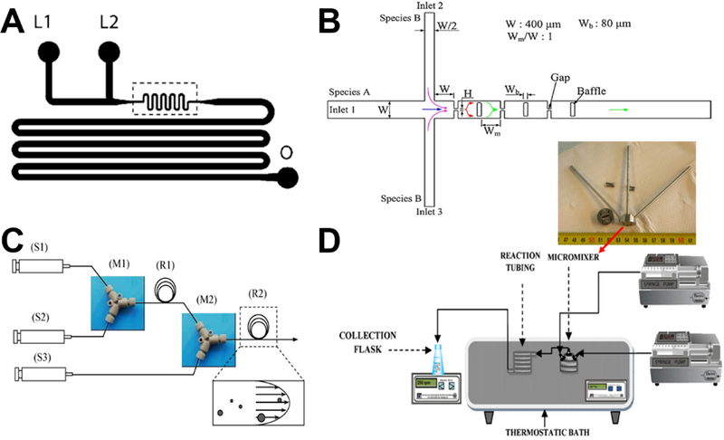
Laminar flow synthesis of colloidal solid silica spheres can be as simple as two-inlets device with one inlet containing silica precursor (such as tetraethyl orthosilicate, TEOS) and the other catalyst (such as ammonia) (Figure 3A).39 Particle size and its range can be well-controlled by parameters such as linear velocity and mean residence time. For a given laminar flow microreactor design, monodisperse particle distribution is only feasible under the conditions that could minimize axial dispersion. The wider the distribution of residence time, the wider the distribution of particle size.39,53
Figure 3.
Examples of laminar flow microreactors for the synthesis of solid silica sphere. (A) Schematic of microchannel has two liquid inlets (L1 and L2) and one outlet (O). Reproduced with permission from ref.39. (B) Schematic diagram of the baffled micromixer with three mixing units. Reproduced with permission from ref.45. (C) Schematic diagram of microreactor system for silica synthesis. (S1), (S2), and (S3) are syringe for TMOS, HCl, and PEI polymer in Tris-HCl buffer solution, respectively. (M1) and (M2) are Y-shaped mixers. (R1) is the reaction tube for hydrolysis, (R2) is the reaction tube for silica precipitation. Reproduced with permission from ref.46. (D) Experimental setup using standard slit interdigital micromixer for the continuous silica particle synthesis. Reproduced with permission from ref.44.
For realizing the high throughput of microreactor, enhanced fluid mixing at high flow velocity with a short mixing length is essential. However, conventional microreactors having meander micromixers were always operated at low flow velocity together with relative long mixing microchannel length. To achieve an effective mixing for a wide-range flow rate in silica nanoparticles synthesis, researchers developed the planar baffled micromixer (Figure 3B), which can greatly enhance the mixing performance through the convection-dominant mechanism at high flow rates and the diffusion-dominant mechanism at low flow rates. The sizes of solid silica spheres decreased with increasing flow rate and reaction temperature.45
Compared with batch reactors, microreactors provide fine control over the hydrolysis, nucleation, and particle growth. However, for laminar flow synthesis of silica, deposition of particles on the microchannel walls is almost inevitable, leading to various degrees of clogging and unstable reaction conditions. With the aid of commercial ETFE (Ethylene Tetrafluoroethylene) tubes (Figure 3C), particle deposition could be minimized and constant flow conditions could be maintained.46 When employing polyethylenimine polymer as nucleation catalyst, a significant narrow size distribution of solid silica spheres can be obtained at room temperature from microfluidic reactors compared to batch reactors.41,46 In addition to ETFE tube, commercial-available standard slit interdigital microstructured mixer has been also used to prepare solid silica spheres (Figure 3D).44 The interdigital micromixer allows the inlet streams to divide into 16 substreams and recombined for maximizing the contact area, leading to shorter nucleation time and higher homogeneity in terms of composition and temperature. These resulted in a lower polydispersity, narrower particle size distributions, and higher inter-run reproducibility, compared with the batch systems.
3.1.2. Porous sphere
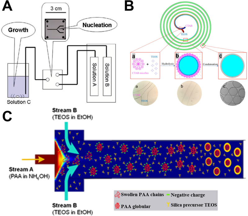
Laminar flow synthesis of porous silica spheres can be realized by the aid of surfactants (such as hexadecyltrimethylammonium salts43,52,56) or polymer (such as polyacrylic acid55). To prepare uniformly sized porous silica sphere, one feasible way is to separate nucleation and growth processes. Specially, partial hydrolysis of silica precursor occurs in the microreactor and then reaction solution containing the as-synthesized nuclei is added into another solution for silica particle growth (Figure 4A). Compared to the particles obtained by batch reactors using identical starting solutions, the silica sphere products obtained using microreactors achieved narrower size distributions as a result of the separation of nucleation and growth processes.43
Figure 4.
Examples of laminar flow microreactors for the synthesis of porous silica sphere. (A) Schematic of the reaction setup for the synthesis of nanoporous silica sphere. Solutions A, B, and C are TEOS/MeOH, MeOH aqueous, and CTAC/MeOH aqueous, respectively. Reproduced with permission from ref.43. (B) Synthesis of submicrometer hollow silica sphere in spiral-shaped microreactor. (a) TEOS in pure ethanol and CTAB micelles in diluted ammonia were flowed into the spiral microchannel; (b) hydrolysis of TEOS occurred at the interface of the two laminar flows; (c) hollow silica spheres were collected at the outlet. Reproduced with permission from ref.56. (C) Formation mechanism of PAA spherical templates in the microreactor with hydrodynamic focusing micromixer for the synthesis of hollow silica nanoparticles. Mixing profile of the solutions was computed from a COMSOL model. Reproduced with permission from ref.55.
For the synthesis of hollow porous silica spheres, our research group first demonstrated the feasibility of spiral-shaped microreactor with one inlet containing silica precursor and the other surfactant in diluted ammonia (Figure 4B).56 Because of the transverse Dean flow effects, the reactants could achieve instantly complete mixing and hollow silica spheres could be obtained in less than one second. Relying on the hydrodynamic focusing micromixer, hollow silica spheres can also be produced in the presence of poly(acrylic acid) as template (Figure 4C). When altering the mixing time by varying flow rates, small-sized uniform hollow nanospheres can be obtained.55
3.1.3. Nonsphere
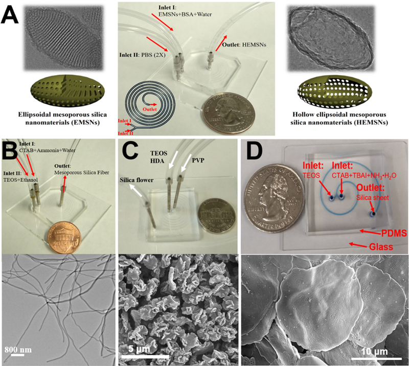
Compared with spherical counterparts, nonspherical materials have been demonstrated, from both theoretical and experimental perspectives, to possess more advanced biological behaviors, such as higher cellular binding efficiency, better drug/protein loading capacity, larger transmembrane internalization rates, and longer circulation time.[10,51–62] Despite of great needs, controllable synthesis of nonspherical silica materials remains a significant challenge. Our research group first opened up this area using spiral-shaped microreactors with two-inlet flows and fabricated a series of nonspherical silica materials, including hollow ellipsoid,54 fiber,57 flower,58 sheet,60 and triangle.61
Microfluidic synthesis of anisotropic hollow ellipsoidal mesoporous silica nanomaterials was realized by a self-templating method. The as-synthesized ellipsoidal mesoporous silica was mixed with bovine serum albumin protein (surface protective coating agent) as one inlet flow, and phosphate buffered saline (etching agent) was used as the other (Figure 5A). Owing to the rapid and intensive mixing performance of microfluidics, the hollow counterparts can be produced within just several seconds. Comparatively, the batch reactor should need nearly one day.54 Using the templating methods, microreactor can be employed as a general and straightforward platform for the synthesis of hollow cube, hollow rod, hollow belt, and other anisotropic hollow silica materials.59
Figure 5.
Examples of laminar flow microreactors for the synthesis of nonspherical silica, including anisotropic hollow ellipsoidal mesoporous silica (A), mesoporous silica nanofiber (B), mesoporous silica microflower (C), and two-dimensional hollow sandwich-like mesoporous silica nanosheet (D). Reproduced with permissions from ref.54,57,58, and60, respectively.
By choosing specific reactants as inlet fluids, we found that nonspherical silica materials can be collected directly from the outlet at certain flow rates. When using cetyltrimethylammonium bromide (CTAB) and diluted ammonia as one inlet flow and diluted tetraethyl orthosilicate (TEOS) as the other, mesoporous silica fiber can be produced (Figure 5B). The aspect ratios and diameters of silica fiber can be easily tuned by changing the flow rates or the concentrations of reactants.57 When one inlet flow contains polyvinylpyrrolidone (PVP) and the other having TEOS and hexadecylamine (HDA), silica microflower with unique multilayered structure can be obtained at a flow rate as high as 4 mL/min (Figure 5C). The production of silica flower was realized within 94 milliseconds and a yield of nearly 5 grams per hour was achieved.58 In addition to five-run spiral-shaped microreactor, we also demonstrated the feasibility of short-range two-run spiral-shaped microreactor (with a microchannel length of less than 8 cm) for the synthesis of nonspherical silica materials. By choosing CTAB and tetrabutylammonium iodine (TBAI) as one inlet and TEOS as the other, we successfully fabricated two-dimensional mesoporous silica nanosheet with typical hollow sandwich-like bilayer and unique water-ripple-like wrinkle surface (Figure 5D).60
3.1.4. Hierarchical composites
Silica-based hierarchical composites with two or more tailored physicochemical properties are appealing for a variety of biological applications.3,75–78 An outstanding advantage of laminar flow microfluidic synthesis systems is that they conveniently allow a combination of individual reactions into a multistep flow sequence. Given this merit, continuous production of hierarchical nanostructures with fluorescent, magnetic, plasmonic and other properties becomes feasible.
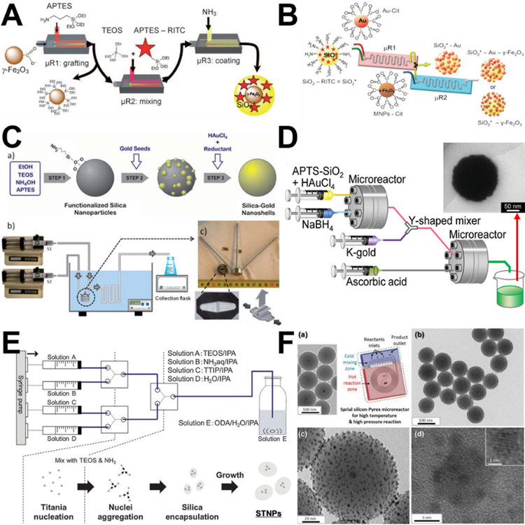
Using three tandem coaxial microreactors for the purposes of grafting, mixing, and coating sequentially, the practicability of multistep synthesis of hierarchical magnetic and fluorescent core-shell Fe2O3-SiO2 was first demonstrated (Figure 6A).42 Similarly, nanoparticles with multifunctional (fluorescent, plasmonic, and superparamagnetic) architectures were self-assembled under a continuous flow (SiO2-Au-Fe2O3, Figure 6B).49 Besides the simplicity of the microfluidic assembly process and the reproducibility of the as-synthesized products, the time of microsynthesis approach was significantly reduced from several hours for the bulk synthesis to a few minutes.42,49
Figure 6.
Examples of laminar flow microreactors for the synthesis of hierarchical composites. (A) Scheme for the continuous synthesis of fluorescent core/shell MNP/silica nanoparticles. Reproduced with permission from ref.42. (B) A two-step microfluidic synthetic procedure for the assembly of multifunctional nanoparticles/fluorescent silica sphere assemblies. RITC: Rhodamine isothiocyanate, Cit: Citrate. Reproduced with permission from ref.49. (C) Experimental process and set-up for the continuous synthesis of SiO2–Au nanoshells. Reproduced with permission from ref.47. (D) Sequential flow synthesis of gold-coated silica particles in the central collision-type microreactor. Reproduced with permission from ref.50 (E) Controlled growth of silica-titania hybrid functional nanoparticles through a multistep microfluidic approach. Reproduced with permission from ref.51. (F) Synthesis of platinum-decorated magnetic silica nanoparticles in microfluidic system. Reproduced with permission from ref.48.
Relying on the simple and scalable merits of microfluidics, laminar flow microreactors have attracted considerable attention for the synthesis of many other hierarchical nanocomposites in the last several years. Considering self-nucleation in the bulk solution phase is suppressed in the microreaction system, no washing is needed after each step. This enables the coupling of seeding and shell growth into a sequential flow in microreactors to synthesize core-shell SiO2-Au nanocomposites through commercial slit interdigital microstructured mixer (Figure 6C) or central collision-type microreactor (Figure 6D).47,50 Similar multistep nucleation-controlled growth method can be also employed to synthesize TiO2-SiO2 (Figure 6E),51 Fe3O4-SiO2-Pt (Figure 6F),48 and Co3O4-SiO2 nanocomposites.53
Our recent studies first demonstrated the flexibility of two-inlets spiral-shaped microreactors in the synthesis of anisotropic multifunctional hierarchical structures. We found that fluorescent dyes, proteins, quantum dots, magnetic nanoparticles, and/or silver nanoparticles could be simultaneously and efficiently assembled into hollow silica sphere,56 silica fiber,57 and silica flower materials.58 In addition, after fabricating sphere-, cube-, rod-, and belt-shaped magnetic nanoparticles through spiral-shaped microreactor, we further successfully coated a silica layer on magnetic particle surface to make differently-shaped core-shell Fe2O3-SiO2 nanocomposites. The shell thickness could be well tuned by changing the flow rate of the TEOS fluid.59
3.2. Discrete segment and droplet flow synthesis
Laminar flow microreactors generally appear to be easier to operate the continuous streams of miscible fluids and more representative of bulk reaction conditions with improved homogeneity. However, fouling and clogging are unavoidable in most of the continuous flow reactors. Comparatively, discrete segment and droplet flow microreactors, where an immiscible gas/liquid is injected alongside the reaction mixture, could attenuate these issues to some extent.36,37,79,80 Therefore, discrete flow microreactors, especially droplet flow microreactors, have attracted more attention in the synthesis of silica materials since their discovery (Table 3). In the following, we will discuss in detail about the synthesis of solid sphere, porous sphere, nonsphere, and hierarchical composite silica materials in segment and droplet flow microreactors.
Table 3.
Silica materials synthesized from discrete segment and droplet microreactors.
| Microchannel type | Material type | Material size | Material shape | Porous type |
Bioapplication Area |
Ref by Year |
|---|---|---|---|---|---|---|
| Winding | SiO2 | 277–540 nm | Sphere | Solid | N/A | 200439 |
| Winding | SiO2 | 200–300 nm | Sphere | Solid | N/A | 200440 |
| Winding | SiO2@TiO2 | ~250 nm | Sphere | Solid | N/A | 200781 |
| Cross-Winding | SiO2 | ~15–35 μm | Sphere | Mesopore (>5 nm) | N/A | 200882 |
| T junction | SiO2 | 0.25–0.5 mm (Sphere); 1.1×2.3–4.7 mm (Rod) | Sphere; Rod | Solid | N/A | 200883 |
| Cross junction | SiO2 | ~1 μm | Sphere | Mesopore (6.4 nm) | N/A | 200884 |
| T junction | SiO2 | ~100 μm | Sphere | Hollow | N/A | 200985 |
| Coflow and flow-focusing | SiO2 | ~50 μm | Nonsphere polygon | Hollow | N/A | 200986 |
| Cross junction | SiO2 | 130 μm | Sphere | Hollow; mesopore (2 nm) | Iodine adsorption | 201087 |
| Cross junction | SiO2-Chitosan | 250 μm | Sphere | Macropore | BSA immobilization | 201088 |
| Coflow-Winding | SiO2 | 1–5 μm | Sphere | Mesopore (4.8 nm) | N/A | 201089 |
| Coflow-Winding | SiO2 | 1–15 μm | Sphere | Mesopore (4.8 nm) | N/A | 201090 |
| Flow-focusing | QDs@SiO2 | ~5 μm | Sphere | Hollow | Ultrasound image; lysozyme immobilization | 201091 |
| Coflow and flow-focusing | SiO2 | 29 μm | Sphere | Hollow | N/A | 201092 |
| T junction-Winding | SiO2@Au | 177–260 nm | Sphere | Solid | N/A | 201093 |
| Y junction-cross junction | SiO2 | 63 nm | Sphere | Solid | N/A | 201146 |
| Flow-focusing | SiO2 | 7–50 μm | Doughnut | Solid | N/A | 201194 |
| Coflow | Chitosan@TS-1 | 200–600 μm | Sphere | Macropore | N/A | 201195 |
| Coflow | SiO2-ETPTA@Ag | 77 μm | Sphere | Solid | BT SERS detection | 201196 |
| Coflow | SiO2 | 100–200 μm | Sphere | Hollow; mesopore (2–38 nm) | N/A | 201197 |
| Coflow | SiO2@TiO2 | 100–300 μm | Sphere | Solid | N/A | 201198 |
| Coflow | Fe2O3@SiO2@Pt | 100 μm | Sphere | Mesopore (18 nm) | IBA oxidation | 201248 |
| Flow-focusing | SiO2-FITC | 50–350 nm | Sphere | Solid | N/A | 201299 |
| Flow-focusing | SiO2 | 1.4–14.6 μm | Sphere | Hollow; mesopore (7.44 nm) | N/A | 2012100 |
| Coflow | SiO2-HDDA | ~0.5 μm | Patchy | Mesopore | N/A | 2012101 |
| Cross junction | SiO2 | 7.7 μm | Sphere | Mesopore (3.4–6 nm) | N/A | 2013102 |
| Flow-focusing | SiO2-lipid | ~25 μm | Sphere | Mesopore (13.4 nm) | FFB, FSM, MTX, and RTD drug loading | 2013103 |
| Coflow | SiO2-Chitosan | 420 μm | Sphere | Mesopore (<5 nm) | Cu(II) adsorption | 2013104 |
| Coflow | SiO2-Fe3O4 | 150 μm | Sphere | Mesopore | Optical encoding | 2013105 |
| T junction | SiO2@Au | 230 nm | Sphere | Solid | N/A | 2013106 |
| T junction | SiO2 | ~100 μm | Raspberry-like | Solid | N/A | 2013107 |
| T junction | SiO2 | 90–185 μm | Sphere; filbert-like | Solid; hollow | N/A | 2014108 |
| Coflow and flow-focusing | SiO2 | ~200 μm | Sphere; disk | Mesopore | N/A | 2014109 |
| Coflow | SiO2-PEGDA | ~200–1000 μm | Rod; cuboid; disk | Solid | Optical encoding | 2014110 |
| Coflow and flow-focusing | SiO2-Dextran | 150–400 nm | Sphere | Mesopore | PTX, SFN, and MTX drug loading | 2015111 |
| T junction | SiO2@Fe2O3 | ~100 nm | Sphere | Solid | N/A | 2015112 |
| T junction | SiO2@Au | ~175 nm | Sphere | Solid | N/A | 2015113 |
| Coflow and flow-focusing | SiO2-PEGDA | ~100–150 nm (diameter) | Fiber | Macropore | N/A | 2016114 |
| Y junction and T junction | SiO2-Cell | 1.3–2.9 mm | Sphere | Solid | E. coli encapsulation | 2016115 |
| T junction | SiO2; Au@SiO2 | ~100–350 nm | Sphere | Solid (Au@SiO2); Mesopore (SiO2) | N/A | 2016116 |
| Slit interdigital | SiO2-FITC | 10–65 nm | Sphere | Solid | N/A | 2017117 |
| T junction | SiO2-Fe3O4 | 260 μm | Sphere | Mesopore | OTA adsorption | 2017118 |
| Flow-focusing | SiO2 | ~10–30 μm | Sphere | Hollow; mesopore (5.9 nm) | N/A | 2017119 |
| T junction | SiO2 | 187 μm | Sphere | Mesopore-macropore | DEX drug loading | 2018120 |
| Cross junction | SiO2-PCL | ~50 μm | Sphere | Solid; macropore | SOD and CAT immobilization | 2018121 |
| Coflow | SiO2-PLGA | ~200 μm | Sphere | Hollow; mesopore | DFO drug loading | 2018122 |
| Cross junction | PDT@SiO2 | ~90 μm | Sphere | Solid | N/A | 2018123 |
Abbreviations: BSA: Bovine serum albumin; BT: Benzenethiol; CAT: Chloramphenicol acetyltransferase; DEX: Dexamethasone; DFO: Deferoxamine; ETPTA: Ethoxylated trimethylolpropane triacrylate; FFB: Fenofibrate; FITC: Fluorescein isothiocyanate; FSM: Furosemide; HDDA: 1,6-hexanediol diacrylate; IBA: 4-isopropyl benzaldehyde; MTX: Methotrexate; N/A: Not Applicable; OTA: Ochratoxin A; PCL: Polycaprolactone; PDT: Poly(1,10-decanediol dimethacrylate-co-trimethoxysillyl propyl methacrylate); PEGDA: Poly(ethylene glycol) diacrylate; PLGA: Poly(lactic-co-glycolic acid); PTX: Paclitaxel; QDs: Quantum dots; RTD: Ranitidine; SERS: Surface-enhanced Raman scattering; SFN: Sorafenib; SOD: Superoxide dismutase; TS-1: Titanium silicate molecular sieves.
3.2.1. Solid sphere
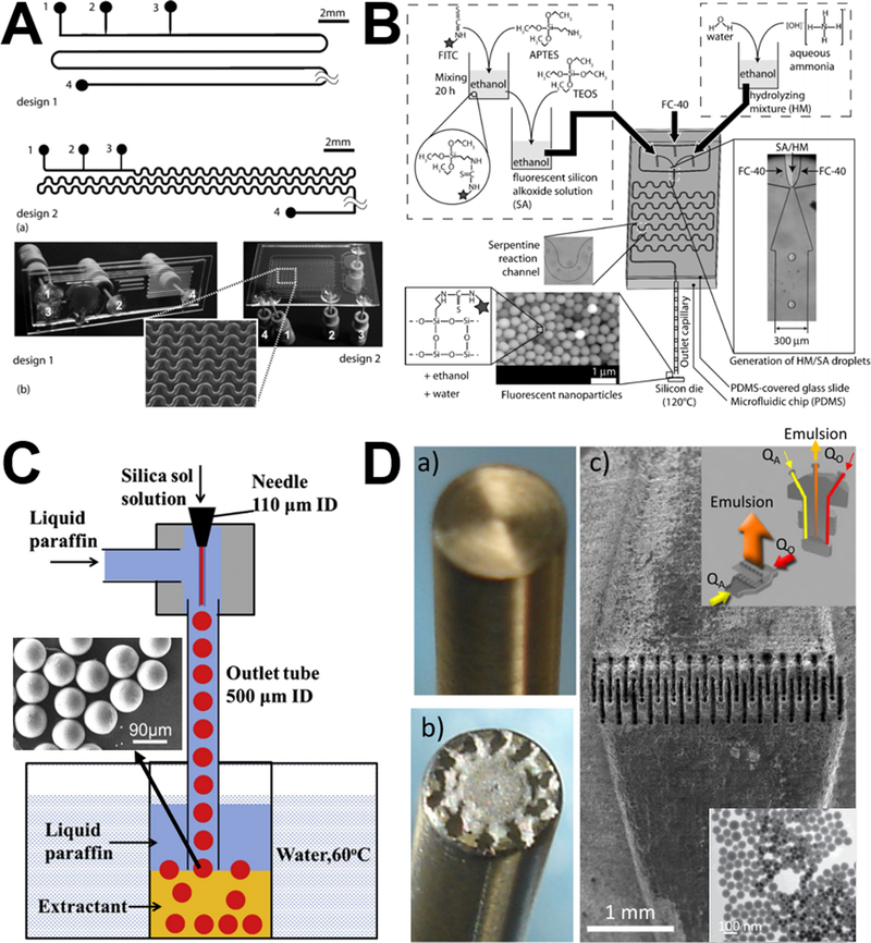
Segment gas-liquid flow microreactors could eliminate axial dispersion effects and thus yield silica spheres of better quality than laminar flow microreactors.39,46 Through quantifying the recirculation motion in liquid segments and the symmetric characteristics of the recirculations associated with gas-liquid flows, it was found that the geometries of segment microreactors significantly affect the mixing performance. Even minor surface roughness property and the compressibility of gas phase could induce loss of symmetry and enhance mixing across the centerline of straight microchannel, while mixing could be further accelerated in meandering microchannel by the periodic switching of recirculation patterns across the microchannel center (Figure 7A).40 This phenomenon endows a narrowed liquid-phase residence time distribution in segmented flows, where narrow particle size distributions of solid silica spheres could be obtained compared with the laminar flow counterparts.39,40,46
Figure 7.
Examples of discrete segment and droplet microreactors for the synthesis of solid silica sphere. (A) Segmented gas-liquid flow microreactors with straight-walled channels (design 1) and meandering channels (design 2) for solid silica sphere synthesis. Number 2 is the gas inlet. Reproduced with permission from ref.40. (B) Procedure and setup for the droplet-based synthesis of silica sphere. Reproduced with permission from ref.99. (C) Droplet synthesis of silica microsphere. Reproduced with permission from ref.108. (D) Microfluidic interdigital mixer used to produce the silica nanosphere by microchannel emulsification. Reproduced with permission from ref.117.
Droplet-based microreactors for the synthesis of solid silica spheres are implemented by a continuous aqueous phase and a dispersed oil phase, which can be FC-40 fluorinert oil (Figure 7B),99 silicon oil,83 liquid paraffin (Figure 7C),108 cyclohexane and 1-hexanol (Figure 7D).117 Due to the precise control of reagent concentrations and residence time, synthesis in droplets could lead to a faster reaction and allow drastically improved silica nanosphere size uniformity compared with conventional bulk synthesis methods.99 By varying the flow rates of continuous and dispersed phases, sizes of solid silica spheres from droplet flow microreactors can be controlled, and even hundreds of micrometer- or millimeter-scale silica particles can be continuously produced,83 which is generally hard to achieve from laminar flow microreactors. Droplet microreactor can be also employed to assist the formation of solid silica microsphere by immersing the formed monodisperse silica sol droplets into the extractant solvent fatty acid methyl ester at room temperature (Figure 7C).108 In addition, combining emulsion technique and interdigital mixers, droplet microreactors could achieve high throughput production with a high reproducibility (Figure 7D).117
3.2.2. Porous sphere
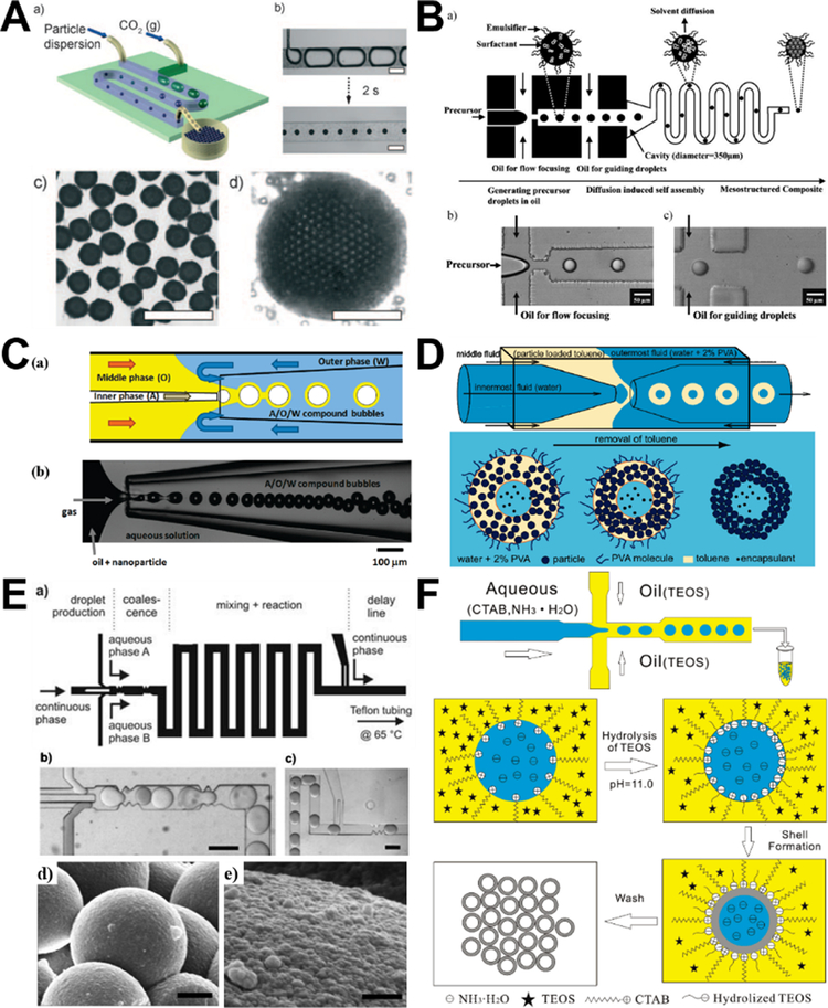
Discrete microreactors for the synthesis of porous silica sphere are generally driven by the assembly of nanosized silica particles to form around tens of micrometers products. Most studies in this area reported to date are droplet-based microreactors, research methods on segment flow microreactors are very few. Gas-liquid interface formation of hollow porous silica sphere can be realized by local perturbations of pH on the length scale of an individual bubble. Specifically, after generation of monodisperse gas bubbles in an aqueous dispersion of anionic silica nanoparticles, the rapid dissolution of gas could result in the shrinkage of bubbles and increase the acidity of the solution in the neighborhood of the bubbles. This leads to the adsorption of silica nanoparticles at the gas-liquid interface driven by the chemically induced in situ change in the surface energy of the particles (Figure 8A). This method enables single-step production of silica armored bubbles with narrow polydispersity (below 5%) and high producibility (up to 3000 bubbles per second).85
Figure 8.
Examples of discrete segment and droplet microreactors for the synthesis of porous silica sphere. (A) Microfluidic assembly of armored bubble-like colloidal silica by dissolving CO2. Reproduced with permission from ref.85. (B) Generation of monodisperse mesoporous silica microspheres using microfluidic diffusion-induced self-assembly. Reproduced with permission from ref.82. (C) Microfluidic fabrication of silica nanoparticles-shelled bubbles using air-in-oil-in-water (A/O/W) compound bubbles as templates. Reproduced with permission from ref.92. (D) Schematic illustration of the double emulsion generation process in a double microcapillary device (top) and the formation of colloidosomes by solvent removal (bottom). Reproduced with permission from ref.97. (E) Template-free preparation of mesoporous silica spheres through a double step-emulsification microfluidic device. Reproduced with permission from ref.90. (F) Schematic illustration of the droplet microfluidic approach for preparing monodisperse hollow silica microsphere through interfacial polymerization in water-in-oil droplets. Reproduced with permission from ref.87.
For the droplet flow microreactors, many studies relied on the solvent evaporation or solvent diffusion methods for the self-assembly formation of porous silica sphere. Microfluidic diffusion-induced self-assembly, which combines microfluidic generation of uniform droplets and subsequent in situ rapid solvent diffusion-induced self-assembly inside the microchannel, can be easily implemented for the synthesis of monodisperse porous silica microspheres.82,120 The particle size can be controlled by simply adjusting the microfluidic conditions such as flow focusing geometry and relative flow rates of two immiscible solutions (Figure 8B).82 Similarly, hollow porous silica sphere can be generated in capillary microfluidic device using either air-in-oil-in-water bubble templating assembly method (Figure 8C) or double emulsion templating assembly method (Figure 8D). Upon the evaporation of the organic solvent, the silica nanoparticles in the oil layer form a stiff shell at the interface and yield porous silica microsphere.92,97
In addition to self-assembly method, porous silica microspheres can be generated from optimized droplet-based sol-gel methods. For examples, the sol-gel reaction can be activated by coalescing droplet pairs and fast mixing inside the coalesced droplets using a double step-emulsification device (Figure 8E), and the size can be easily tuned by varying the flow rates, the dimensions of microfluidic device, and the chemical concentrations;89,90 By templating silica microparticles with a specially designed surfactant micelle/oil nanoemulsion mixture, silica spheres with hierarchical porosity can be formed, the size distribution and surface area of the smaller micelle-templated pores are controlled as a sequence of altering the hydrophobic chain length of the molecular surfactant templates.84,102 Similarly, hollow porous silica microspheres with controllable size can be produced via hydrolysis and polymerization of silica precursor at the interface of water-in-oil droplets by microfluidic-assisted sol-gel process (Figure 8F).87,100,108,119
3.2.3. Nonsphere
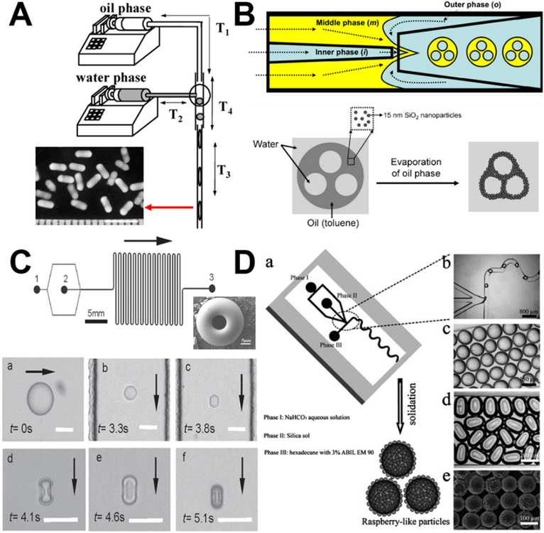
In droplet formation of nonspherical silica, the ability to control the local flow field via fabrication of complex microscale geometries enables control over the deformation or breakup of every individual droplet, thus allowing control over particle morphology. By placing the microchannel vertically, the droplets can adopt a rod shape because the confinement suppresses relaxation of their shape to the spherical equilibrium one. Aspect ratios of the rod-like droplets can be easily controlled by changing the ratio of the droplet volume to the diameter of the cylindrical microchannel (Figure 9A).83 Nonspherical silica colloidosomes with multiple compartments can be obtained using a glass capillary microfluidics that combines a co-flow and a flow-focusing geometry to prepare W/O/W double emulsions (Figure 9B), where a different number of internal aqueous drops are confined in the oil drop containing hydrophobic silica nanoparticles. During the oil removal, the internal water-in-oil interface retains their spherical shape and the outer oil-in-water deforms, leading to the formation of nonspherical silica with multiple compartments inside.86 Such solvent evaporation-induced structural deformation can be employed to fabricate a series of other nonspherical silica materials, including doughnut-shape (Figure 9C),94 raspberry-shape (Figure 9D),107 filbert-shape,108, and disk-shape.109 In addition, by photo-polymerizing the droplet templates in situ of the confined microchannels, anisotropic silica particles with the same ordered colloidal structures can be generated,110 which will be discussed further in the following section.
Figure 9.
Examples of discrete segment and droplet microreactors for the synthesis of nonspherical silica. (A) Experimental set-up for the synthesis of anisotropic silica rod particles. Reproduced with permission from ref.83. (B) Generation of nonspherical colloidosome from W/O/W double emulsions with multiple internal aqueous drops using a glass capillary microfluidic channel. Reproduced with permission from ref.86. (C) Template-free formation of monodisperse doughnut-shaped silica microparticles by droplet-based microfluidics. Reproduced with permission from ref.94. (D) Microfluidic synthesis of monodisperse hierarchical silica particles with raspberry-like morphology. Reproduced with permission from ref.107.
3.2.4. Hierarchical composites
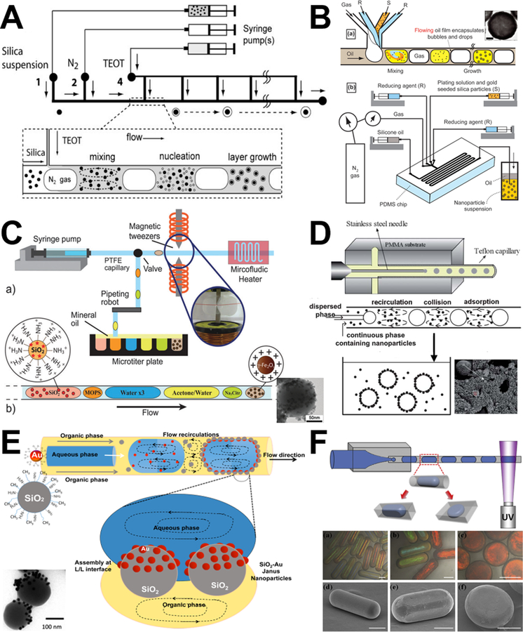
Discrete flow synthesis of hierarchical composites has been studied extensively compared with other particle synthesis systems mentioned above. There are a variety of silica-based inorganic-inorganic and inorganic-organic core-shell and Janus materials formed through segment and droplet flow microreactors. To date, gas-liquid segment flow microreactors, although still relatively few reported studies, have been demonstrated their great potential in the controllable synthesis of core-shell silica materials, including SiO2@TiO2 (Figure 10A),81 SiO2@Au (Figure 10B),93,106 and Au@SiO2.116 Since batch synthesis of core-shell silica materials always suffers from difficulties in controlling overcoat thickness, maintaining a narrow size distribution, and avoiding secondary nucleation and aggregation, segment flow microreactors provide efficient alternative solutions by the distinctive merit of highly flexible designs, such as multi-point addition of shell reactant (Figure 10A) and multiphase inlet motifs (Figure 10B).
Figure 10.
Examples of discrete segment and droplet microreactors for the synthesis of hierarchical composites. (A) Microfluidic synthesis of titania shells on colloidal silica (SiO2@TiO2) at the gas-liquid interface. Reproduced with permission from ref.81. (B) Microfluidic foam generation of plasmonic nanoshell on silica surface. Reproduced with permission from ref.93. (C) Microfluidic droplet flow synthesis of silica nanoparticles coated with iron oxide nanoparticles. Reproduced with permission from ref.112. (D) Droplet flow synthesis of silica-chitosan hybrid microsphere in a co-axial microfluidic device. Reproduced with permission from ref.95. (E) Droplet liquid-liquid interfaces generated in a microfluidic device for assembling Janus inorganic nanohybrids (SiO2-Au). Reproduced with permission from ref.113. (F) Schematic illustration of the microfluidic device used for the generation of anisotropic particles with various geometries. The resultant droplets were solidified in situ using UV irradiation. Reproduced with permission from ref.110.
Droplet flow microreactors enable the production of inorganic-inorganic (Figures 10C&E) and inorganic-organic (Figures 10D&F) silica composites at the oil-aqueous interface. The formation of most silica-based inorganic-inorganic core-shell and Janus hybrids relies on microfluidics-assisted self-assembly method. For example, using different geometries of microchannels, silica-magnetic composites can be produced through one-step emulsion process105,118 or multistep sequential manipulation process (Figure 10C);112 core-shell silica-titania can be obtained using one-step emulsion process in co-axial microdevice;98 Janus silica-gold nanohybrid can be assembled at the interface of microdroplets produced by emulsification of an aqueous suspension of gold nanoparticles in an organic phase composed of a suspension of silica nanoparticles in cyclohexane (Figure 10E).113 Similarly, silica-based inorganic-organic hybrids with controlled structures and desired properties can be fabricated using microfluidic technology owing to its capability for precise control over the emulsification process and for generating monodispersed compound droplets inside microchannels. Of those organic components of silica-polymer composites, chitosan is the most favorable one due to its inherent abundant amine groups that are readily capable for heavy metal ions adsorption, protein immobilization, and molecular catalysis.88,95,104 In addition, for the synthesis of silica-polymer hybrids, chemical crosslinking (such as glutaraldehyde88,95,104) and physical crosslinking methods (such as ultraviolet irradiation96,101,110,114,123) are always used during the solidification process. However, the former generally can produce only spherical composites (Figure 10D),95 while the latter enables the synthesis of anisotropic hierarchical structures, such as fiber,114 patchy particle,101, rod, cuboid, and disk (Figure 10F).110
4. Biomedical applications of silica materials from microfluidics
Silica materials synthesized from microfluidic reactors have demonstrated with more advanced properties than those from conventional batch reactors, such as uniform size distributions, ease of functionalization, flexible morphology tunability, and facile scale-up. These features make the resultant silica materials derived from microreactors attractive for bioapplications in bioimaging, protein immobilization, bioadsorption, drug delivery, liquid biopsy, etc. In the following, we will provide an overview of the application progress of silica biomaterials from continuous and discrete microreactors.
4.1. Bioimaging
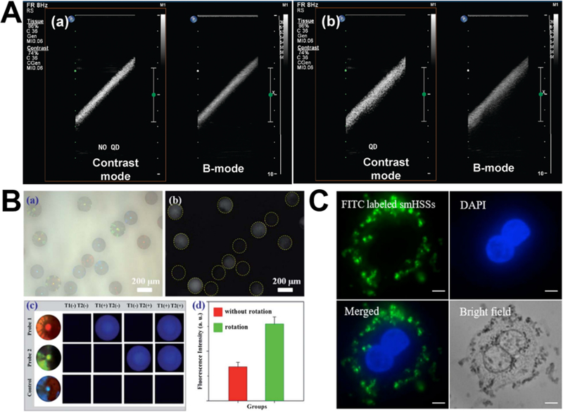
Microfluidics provides great opportunities for the synthesis of new silica bioimaging agents by either assembly91,105,110 or sol-gel chemical reactions.56 For the synthesis of efficient ultrasound imaging agent, droplet microreactors could easily assemble silica-coated CdSe/ZnS QDs nanoparticle on the surface of perfluorocarbon microbubbles via the electrostatic attraction between nanoparticles and microbubble shell. In vitro ultrasound images demonstrated that, compared to microbubbles alone, silica-QDs-incorporated microbubbles obviously improved the signal intensity on both contrast-specific imaging and B-mode imaging (Figure 11A).91 Based on self-assembly of droplet microreactors, silica-magnetic Janus and nonspherical photonic crystal particles can be also produced by the emulsification and photo-polymerization process, respectively.105,110 The distinguishable features of resultant particles make them ideal barcodes for optical encoding. DNA multiplex coding bioassay showed that these photonic crystal particles have a great encoding capacity and obvious detection signal enhancement within 20 min (Figure 11B). Using two-inlet spiral-shaped laminar flow microreactor, our research group developed a facile protocol to synthesize fluorescent silica microspheres by just adding fluorescent dyes, proteins, or QDs into one inlet flow. The as-synthesized fluorescent silica particles can effectively interact with SK-BR-3 cancer cells with negligible cytotoxicity (Figure 11C).56 These preliminary results revealed the promising potential of silica bioimaging agents from microreactors. However, further studies are needed to demonstrate their practical applicability in the clinical settings.
Figure 11.
Microfluidic synthesis of silica-based biomaterials for ultrasound imaging (A), optical encoding (B), and cell imaging (C). (A) In vitro ultrasound images of an Opticell filled with unloaded microbubbles (a) and microbubbles loaded with silica-coated QDs. Reproduced with permission from ref.91. (B) Microfluidic generation of magnetic-silica Janus photonic crystal particles for optical encoding. Reproduced with permission from ref.105. (C) Fluorescent images of SK-BR-3 cells after incubated with hollow silica spheres for 4 hours. Reproduced with permission from ref.56.
4.2. Protein immobilization
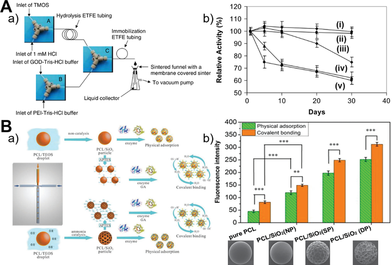
The immobilization of proteins on microreactor-generated silica materials is feasible by either microfluidic process (Figure 12A–a) or conventional batch process (Figure 12B–a). Better control of the operation parameters in the microfluidic system over batch methodology is expected to enable the production of silica particles with the optimal structural properties for efficient protein immobilization with long-term stability. Continuous laminar flow microreactor was demonstrated to successfully immobilize glucose oxidase (GOD) in the presence of polyethylenimine (PEI) polymer or R5 peptide. Microfluidics-immobilized GOD shows no loss of activity over at least a 30 day period, however, batch immobilization causes GOD significantly reduced activity after ten days (Figure 12A–b).41 Similarly, droplet flow microreactor allows one-step process for the immobilization of bovine serum albumin (BSA) protein during the synthesis of chitosan-silica microspheres. The existence of silica in the chitosan spheres can enhance protein loading capacity (up to 50 mg/g), which further increases with increased silica precursor concentration.88 In addition to the precise control on particle size and shape, droplet-based microreactor also permits to adjust the surface porosity of poly(ε-caprolactone)/silica (PCL/SiO2) hybrid microbeads for effective protein coimmobilization. In comparison to physical adsorption, covalent binding favors more remarkably IgG and BSA coimmobilization, and the higher degree of surface porosity makes the higher loading amounts of proteins (Figure 12B–b).121 Although these results revealed important roles of immobilization methodology and particulate structure on protein immobilization, the protein loading efficiency on silica materials is still very low and more efforts need to be made to improve the synergistic performance through multiprotein coimmobilization.
Figure 12.
Microfluidic synthesis of silica-based biomaterials for protein immobilization. (A) Continuous flow microfluidic reactor system used for the immobilization of GOD in silica nanoparticles (a) and the comparison of the stability of immobilized GOD and GOD in solution (b, from i to v are microreactor system using R5 peptide, microreactor system using PEI, batch reactor system, two-step batch reactor system with silica particle synthesis firstly and then GOD immobilization using PEI, and free GOD in solution, respectively). Reproduced with permission from ref.41. (B) Microfluidic fabrication of hierarchical PCL-silica hybrid microbeads for multiprotein coimmobilization (a) and the comparison of the fluorescence intensity of cy3-BSA (red) and FITC-IgG (green) immobilized microbeads. NP: no pore; SP: shallow pore; DP: deep pore. Reproduced with permission from ref.121.
4.3. Bioadsorption
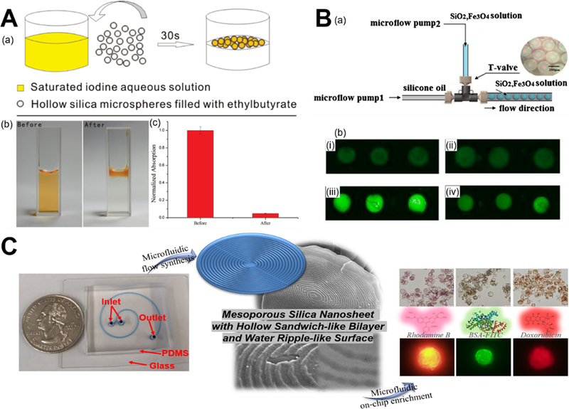
For the purpose of ions and molecules adsorption, droplet flow microreactors are generally employed to synthesize a couple of hundred micrometers-sized silica materials with typical porous structure.87,104,118 The synthesized hollow silica microspheres from droplet flow microreactors offer a much higher storage capacity compared to those from batch reactors, making them suitable for iodine adsorption. The removal rate of iodine could achieve over 95% within 30 seconds after adding hollow microspheres (Figure 13A).87 Silica-doped porous chitosan/silica hybrid microspheres were also demonstrated to have faster adsorption kinetics and larger equilibrium adsorption amount of Cu(II) compared to the porous chitosan microspheres.104 In addition to ions, photonic encoding magnetized silica microspheres from droplet microreactor can be applied to aptamer-based adsorption of the food toxin Ochratoxin A (OTA) with up to 80% enrichment efficiency (Figure 13B).118 Different from the above-mentioned batch process for bioadsorption, our group first investigated the feasibility of microfluidic process for on-chip enrichment of biomolecules in two-run spiral-shaped laminar flow microreactor. The two inlets of microfluidic device, one containing mesoporous silica nanosheet as adsorbent and the other containing Rhodamine B, BSA-FITC, or Doxorubicin as adsorbate, were operated at different flow rates for examining the enrichment capacity (Figure 13C). Both theoretical analysis and experimental tests demonstrated the rapid and efficient on-chip enrichment capacity of mesoporous silica nanosheet. The lower the flow rate ratio of adsorbate to adsorbent, the higher the adsorption rates of silica material. The maximum on-chip adsorption amount of Rhodamine B, BSA-FITC, and Doxorubicin achieved 1.24, 0.55, and 0.93 gram per gram of silica sheet material, respectively.60 Compared to batch adsorption process, microfluidic process could realize ultrafast on-chip enrichment of ions and molecules at millisecond time scale, however, the throughput is still a big issue.
Figure 13.
Microfluidic synthesis of silica-based biomaterials for ions and molecules adsorption. (A) Droplet flow synthesis of hollow silica microspheres for iodine adsorption. Reproduced with permission from ref.87. (B) Droplet synthesis of porous photonic encoding magnetized silica microspheres (PEMSMs) for OTA enrichment. Figures i-iv are carbonylated surfaces of PEMSMs, physical adsorption of OTA aptamer on the surface of PEMSMs, covalent bonding of OTA aptamer on the surface of PEMSMs with NHS/EDC activation, and covalent bonding of OTA aptamer with biotin-streptavidin link system on the surface of PEMSMs, respectively. Reproduced with permission from ref.118. (C) Microfluidic synthesis of two-dimensional hollow sandwich-like mesoporous silica nanosheet with water ripple-like surface for on-chip enrichment of Rhodamine B, BSA-FITC, and Doxorubicin. Reproduced with permission from ref.60.
4.4. Drug delivery
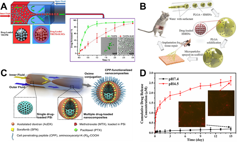
Compared to post-synthesis batch loading approach of drugs,54,56,120 microfluidic approach permits one-step encapsulation of aqueous insoluble and aqueous soluble drugs during the formation of resultant silica-based biomaterials, which significantly simplifies the drug loading procedures.111,122 To achieve sustained drug delivery, microfluidics can encapsulate drug-loaded thermally hydrocarbonized porous silicon (THCPSi) microparticles within solid lipid microparticles (SLMs). The lipid coating not only enhances the cytocompatibility, but also achieves at least 1.3 times longer release time than that from THCPSi (Figure 14A).103 For simultaneous drug loading during material synthesis, microfluidics technology not only avoids the imposition of large shear and strong oscillation on encapsulated drugs, but also tailors the porous structures of silica materials to alter their surface areas. These unique features endow the silica materials with high-drug loading capacity and controlled drug release at a desired rate. Using double emulsion droplet microfluidic system, deferoxamine drug-loaded hierarchically porous silica microparticles as a new composite scaffold successfully promoted neovascularization, collagen deposition, and tissue repair in a rat model of a partial abdominal wall defect (Figure 14B).122 In addition to single drug loading, microfluidic device also permits the simultaneously loading of multiple drugs with different physicochemical properties in a ratiometric control. The release kinetics of all the drug payloads can be well controlled by the decomposition rate of the outer polymer matrix on porous silica surface (Figure 14C).111 Furthermore, most of microfluidic drug loading systems to date are established on the basis of droplet flow microreactors. Recently, our group first developed laminar flow microreactor drug loading system with one inlet flow containing CTAB surfactant and doxorubicin drug and the other inlet flow containing silica precursor. The drug molecules can be uniformly distributed into the resultant mesoporous silica fiber materials with an encapsulation efficiency of 12.34%, and pH-dependent sustained drug release profiles were observed over 15 days (Figure 14D).57 Microfluidics provides great convenience for simplifying the drug loading process, however, it is noted that it still has much room to increase the drug loading efficiency, especially for multidrug codelivery systems.
Figure 14.
Microfluidic synthesis of silica-based biomaterials for drug delivery. (A) Microfluidic synthesis of mesoporous silica-solid lipid microcomposite for aqueous insoluble and aqueous soluble drugs delivery. Reproduced with permission from ref.103. (B) Schematic diagram of a capillary microfluidic system for generating the W/O/W double emulsion droplets, the fabrication process of the hierarchically porous composite microparticles for controllable drug delivery, the generation of microparticles-coated scaffold and its application in abdominal wall repair. Reproduced with permission from ref.122. (C) Schematics of the process to synthesize cell penetrating peptide-functionalized multidrug-loaded PSi@AcDX-CPP. Reproduced with permission from ref.111. (D) Drug release profiles of microfluidics-enabled one-step production of doxorubicin-loaded mesoporous silica fiber and two representative fluorescent images after drug release tests. Reproduced with permission from ref.57.
4.5. Liquid biopsy
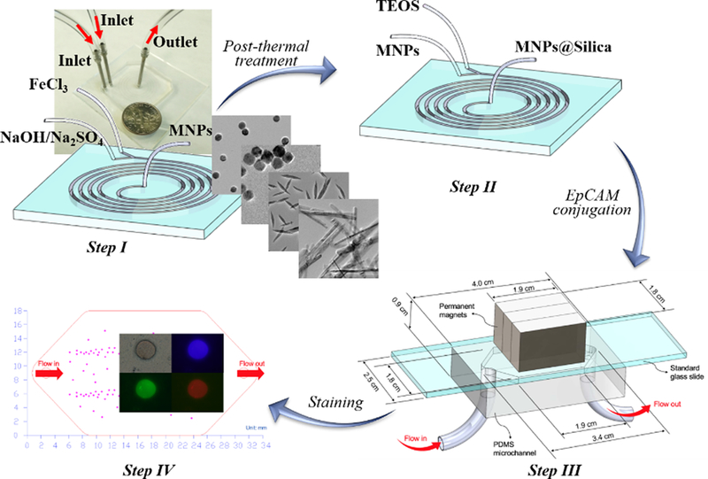
Compared to conventional tissue biopsies that take long time to process before analysis and be costly, painful, and difficult to obtain, liquid biopsy represents a new non-invasive approach that has been extensively studied over the last decade and holds great promise.124 Although great progress of nanomaterials-based circulating tumor biomarkers screening has been made, the structure-property-function relationship behind them is still missing. Our research group first employed microreactor to fabricate differently shaped silica-magnetic immunomaterials and examined the effect of particle shape on the screening performance of circulating tumor cells (CTCs).58,59 In one recent study, we successfully fabricated sphere-, cube-, rod-, and belt-shaped magnetic nanoparticles and then coated them with a thin silica shell for conjugating epithelial cell adhesion molecule (EpCAM) antibody and improving the cytobiocompatibility (Figure 15). The screening results showed that belt-shaped nanoparticles having the largest aspect ratio exhibited the highest capture rates in MCF-7 and MDA-MB-231 tumor cells-spiked whole blood samples, followed by rod-shaped nanoparticles, sphere- and cube-shaped nanoparticles had the relatively lowest capture efficiencies.59 In another study, we created silica-magnetic microflower with unique multilayered structures in spiral-shaped laminar flow microreactor at a reagent flow rate of 4 mL/min and the production yield could achieve nearly 5 grams per hour. Owing to the recognizable flower morphology, the interactions between cancer cells and silica-magnetic particles was easily identified, providing a convenient way to track the CTCs. In addition, the enhanced bioaccessibility from the multilayered silica-magnetic microflower endows it with higher CTCs capture rates toward tumor cells-spiked whole blood samples than commercial standard ferrofluid.58 These preliminary studies demonstrated superior screening performance of nonspherical materials over their spherical counterparts in simulated blood samples, however, real clinical blood samples from cancer patients should be further examined for revealing the practical roles of silica structures in liquid biopsy.
Figure 15.
Microfluidic synthesis of silica-magnetic nanomaterials for circulating tumor cell screening. Reproduced with permission from ref.59.
Besides the bioapplications discussed above, other applications of silica materials have also emerged in the last several years. For examples, silver-decorated silica microspheres from coaxial capillary device exhibited superior surface-enhanced Raman scattering activity for the sensing detection of benzenethiol, 2-naphthalenethiol, and 4-aminothiophenol at the nanomolar level;96 silicon alkoxide cross-linked silica nanoparticle gel microspheres can be employed to encapsulate E. Coli bacteria through microfluidic emulsion system;115 Platinum-decorated silica nanospheres and silver-decorated silica nanofibers showed excellent catalytic activity for the oxidation of aldehyde and the reduction of 4-nitrophenol, respectively.48,57 Given the unique advantages of microfluidics, especially of the precise spatio-temporal control, more broad applications are expected to be made with silica materials.
5. Key observations and future perspectives
The past decade has witnessed the emergence and unprecedented growth of microfluidics technology for silica materials synthesis. Compared to conventional batch synthesis systems, the unique features of microfluidics endow the resultant silica materials with more advanced physicochemical and biological properties. Microreactor-enabled controllable size, shape, porosity, and structure of silica materials help them find their niche in several bioapplication fields such as bioimaging, protein immobilization, bioadsorption, drug delivery, and liquid biopsy. To date, both material synthesis and biological applications established based on laminar flow microreactors and discrete flow microreactors have provided encouraging results, however, there are still many pressing challenges that need to be adequately addressed.
First, low amount of production due to small operating volumes. Small operating volumes of reagents represent one of the biggest advantages of microfluidic reaction systems, which could significantly reduce reagent costs and waste generation during the screening of synthesis parameters. However, this limits the production quantities of silica materials to just gram-scale per hour currently, even when the fluid flow rate was set to milliliters per minute.58 To solve this bottleneck, more rational design of microfluidic devices with parallel multiple modules that allow to handle large volume of reagents should be developed for the scale-up synthesis of silica materials.18
Secondly, low diversity in particle properties. Microfluidics undoubtedly has outstanding capacities in tuning the size, shape, porosity, and structure properties of silica materials. However, as revealed in Tables 2 and 3, most of silica particle sizes are ranging from a couple of hundred nanometers to several hundred micrometers; most silica materials developed to date exhibit spherical shape and small pore size (less than 5 nm); and the structure of silica composites that mostly contain chitosan, gold or iron oxide is relatively simple. To enhance the biological performance of silica materials, nanosized, anisotropic, and multifunctional particles with a wide range of porosity should be developed.9,11,125 This not only requires improvement of microreactor designs, but also needs concerted efforts of researchers from various disciplines such as chemistry, biology, and physics.
Thirdly, lack of inline control for real-time analysis. Full exploitation of microreactor synthesis systems needs real-time information about the chemical reaction progress for an immediate feedback control in the optimization of product’s physicochemical properties. Despite their merits in integration and automation, only very few microfluidic reaction systems have utilized the inline analysis for materials synthesis,126–129 even fewer cases for silica materials with no traceable optical, electronic, fluorescent, and magnetic properties. However, it is expected that, with the development of new miniaturized technological systems, more dedicated analysis tools can be integrated into microfluidic flow reactors for greatly increasing the depth of information available during the formation of silica particles.
Fourthly, insufficient demonstration of merits from microreactors over batch reactors. Most of researchers have neglected the fact that microfluidics is not just an alternative to batch reactors, instead, it is a more advanced platform for the synthesis of silica materials. There have only been very few direct investigations to date showing the advanced merits of microreactors in terms of faster reaction kinetics, narrower particle size distributions, higher reproducibility, and larger application capacity.41,43,44,46,54,60 More parallel studies are in need to examine the differences between microfluidic reaction and batch reaction.
Finally, but not lastly, simple and narrow range of applications. It is evident that, although versatile microreactor platforms and rich reaction methods have been developed for the synthesis of silica materials, their applications dramatically lagged. Most of applications mentioned above (i.e., bioimaging, protein immobilization, bioadsorption, drug delivery, liquid biopsy, etc.) are still in the proof-of-concept stage. There is a long way from the laboratory to industrial/clinical practice, requiring convincing benchmarking and validation of the discoveries and techniques. Therefore, it is suggested that future studies on the rational design and synthesis of microfluidics-enabled silica biomaterials should be more application-oriented.
6. Conclusions
This paper provides a comprehensive review of microfluidics-based development of silica materials with controllable size, shape, porosity, and structure properties, in particular, using laminar, segment, and droplet flow microreactors for a variety of biomedical applications. Despite great advance, microfluidics technology for the synthesis of silica biomaterials is still in its infancy. With rapid ongoing development of multiscale material design, sol-gel chemistry, microfabrication and microfluidic manipulation, silica materials with more rational design for meeting specific bioapplication needs are expected to expedite soon. We envision that the versatility and advantages of microfluidics for silica materials synthesis could open new research frontiers and provide unparalleled opportunities for producing functional materials on-demand with broad applications.
Acknowledgement
The authors are grateful for the financial support from the National Institute of Health (NIH)Director’s Transformative Research Award (R01HL137157), NSF ECCS-1509369, and NorrisCotton Cancer Center Developmental Funds (Pilot Projects).
References:
- 1.Stöber W, Fink A and Bohn E, J. Colloid Interf. Sci, 1968, 26, 62–69. [Google Scholar]
- 2.Kresge CT, Leonowicz ME, Roth WJ, Vartuli JC and Beck JS, Nature, 1992, 359, 710–712. [Google Scholar]
- 3.Barbe C, Bartlett J, Kong L, Finnie K, Lin HQ, Larkin M, Calleja S, Bush A and Calleja G, Adv. Mater, 2004, 16, 1959–1966. [Google Scholar]
- 4.Slowing II, Trewyn BG, Giri S and Lin VS-Y, Adv. Funct. Mater, 2007, 17, 1225–1236. [Google Scholar]
- 5.Du X and He JH, Nanoscale, 2011, 3, 3984–4002. [DOI] [PubMed] [Google Scholar]
- 6.Tang FQ, Li LL and Chen D, Adv. Mater, 2012, 24, 1504–1534. [DOI] [PubMed] [Google Scholar]
- 7.Hao N, Neranon K, Ramström O and Yan M, Biosens. Bioelectron, 2016, 76, 113–130. [DOI] [PMC free article] [PubMed] [Google Scholar]
- 8.Tang L and Cheng J, Nano Today, 2013, 8, 290–312. [DOI] [PMC free article] [PubMed] [Google Scholar]
- 9.Hao N, Li LF and Tang FQ, Int. Mater. Rev, 2017, 62, 57–77. [Google Scholar]
- 10.Hao N, Li L and Tang F, Biomater. Sci, 2016, 4, 575–591. [DOI] [PubMed] [Google Scholar]
- 11.Albanese A, Tang PS and Chan WCW, Annu. Rev. Biomed. Eng, 2012, 14, 1–16. [DOI] [PubMed] [Google Scholar]
- 12.Slowing II, Vivero-Escoto JL, Trewyn BG and Lin VS-Y, J. Mater. Chem, 2010, 20, 7924–7937. [Google Scholar]
- 13.Hao N, Li LF and Tang FQ, J. Biomed. Nanotechnol, 2014, 10, 2508–2538. [DOI] [PubMed] [Google Scholar]
- 14.Mou CY and Lin HP, Pure Appl. Chem, 2000, 72, 137–146. [Google Scholar]
- 15.Abou-Hassan A, Sandre O and Cabuil V, Angew. Chem. Int. Ed, 2010, 49, 6268–6286. [DOI] [PubMed] [Google Scholar]
- 16.Il Park J, Saffari A, Kumar S, Günther A and Kumacheva E, Annu. Rev. Mater. Res, 2010, 40, 415–443. [Google Scholar]
- 17.Sebastian B and Dittrich PS, Annu. Rev. Fluid Mech, 2018, 50, 483–504. [Google Scholar]
- 18.Whitesides GM, Nature, 2006, 442, 368–373. [DOI] [PubMed] [Google Scholar]
- 19.Hao N, Nie Y and Zhang JXJ, Int. Mater. Rev, 2018, 63, 461–487. [Google Scholar]
- 20.Lin W-Y, Wang Y, Wang S and Tseng H-R, Nano Today, 2009, 4, 470–481. [DOI] [PMC free article] [PubMed] [Google Scholar]
- 21.Lu M, Ozcelik A, Grigsby CL, Zhao Y, Guo F, Leong KW and Huang TJ, Nano Today, 2016, 11, 778–792. [DOI] [PMC free article] [PubMed] [Google Scholar]
- 22.Dendukuri D and Doyle PS, Adv. Mater, 2009, 21, 4071–4086. [Google Scholar]
- 23.Chung BG, Lee K-H, Khademhosseini A and Lee S-H, Lab Chip, 2012, 12, 45–59. [DOI] [PubMed] [Google Scholar]
- 24.Capretto L, Carugo D, Mazzitelli S, Nastruzzi C and Zhang X, Adv. Drug Deliv. Rev, 2013, 65, 1496–1532. [DOI] [PubMed] [Google Scholar]
- 25.Baah D and Floyd-Smith T, Microfluid. Nanofluid, 2014, 17, 431–455. [Google Scholar]
- 26.Wang W, Zhang M-J and Chu L-Y, Acc. Chem. Res, 2014, 47, 373–384. [DOI] [PubMed] [Google Scholar]
- 27.Nightingale AM and de Mello JC, J. Mater. Chem, 2010, 20, 8454–8463. [Google Scholar]
- 28.Phillips TW, Lignos IG, Maceiczyk RM, DeMello AJ and DeMello JC, Lab Chip, 2014, 14, 3172–3180. [DOI] [PubMed] [Google Scholar]
- 29.Rahman M and Rebrov E, Processes, 2014, 2, 466–493. [Google Scholar]
- 30.Shahbazali E, Hessel V, Noël T and Wang Q, Nanotechnol. Rev, 2014, 3, 65–86. [Google Scholar]
- 31.Squires TM and Quake SR, Rev. Mod. Phys, 2005, 77, 977–1026. [Google Scholar]
- 32.Nguyen N-T and Wu Z, J. Micromech. Microeng, 2005, 15, R1–R16. [Google Scholar]
- 33.Culbertson CT, Jacobson SC and Michael Ramsey J, Talanta, 2002, 56, 365–373. [DOI] [PubMed] [Google Scholar]
- 34.Song Y, Hormes J and Kumar CSSR, Small, 2008, 4, 698–711. [DOI] [PubMed] [Google Scholar]
- 35.Mark D, Haeberle S, Roth G, von Stetten F and Zengerle R, Chem. Soc. Rev, 2010, 39, 1153–1182. [DOI] [PubMed] [Google Scholar]
- 36.Song H, Chen DL and Ismagilov RF, Angew. Chem. Int. Ed, 2006, 45, 7336–7356. [DOI] [PMC free article] [PubMed] [Google Scholar]
- 37.Kim JH, Jeon TY, Choi TM, Shim TS, Kim SH and Yang SM, Langmuir, 2014, 30, 1473–1488. [DOI] [PubMed] [Google Scholar]
- 38.Marre S and Jensen KF, Chem. Soc. Rev, 2010, 39, 1183–1202. [DOI] [PubMed] [Google Scholar]
- 39.Khan SA, Günther A, Schmidt MA and Jensen KF, Langmuir, 2004, 20, 8604–8611. [DOI] [PubMed] [Google Scholar]
- 40.Günther A, Khan SA, Thalmann M, Trachsel F and Jensen KF, Lab Chip, 2004, 4, 278–286. [DOI] [PubMed] [Google Scholar]
- 41.He P, Greenway G and Haswell SJ, Nanotechnology, 2008, 19, 315603. [DOI] [PubMed] [Google Scholar]
- 42.Abou-Hassan A, Bazzi R and Cabuil V, Angew. Chem. Int. Ed, 2009, 48, 7180–7183. [DOI] [PubMed] [Google Scholar]
- 43.Shiba K, Kambara K and Ogawa M, Ind. Eng. Chem. Res, 2010, 49, 8180–8183. [Google Scholar]
- 44.Gutierrez L, Gomez L, Irusta S, Arruebo M and Santamaria J, Chem. Eng. J, 2011, 171, 674–683. [Google Scholar]
- 45.Chung CK, Shih TR, Chang CK, Lai CW and Wu BH, Chem. Eng. J, 2011, 168, 790–798. [Google Scholar]
- 46.He P, Greenway G and Haswell SJ, Chem. Eng. J, 2011, 167, 694–699. [Google Scholar]
- 47.Gomez L, Arruebo M, Sebastian V, Gutierrez L and Santamaria J, J. Mater. Chem, 2012, 22, 21420–21425. [Google Scholar]
- 48.Lee S-K, Liu X, Sebastián Cabeza V and Jensen KF, Lab Chip, 2012, 12, 4080–4084. [DOI] [PubMed] [Google Scholar]
- 49.Hassan N, Cabuil V and Abou-Hassan A, Angew. Chem. Int. Ed, 2013, 52, 1994–1997. [DOI] [PubMed] [Google Scholar]
- 50.Watanabe S, Hiratsuka T, Asahi Y, Tanaka A, Mae K and Miyahara MT, Part. Part. Syst. Char, 2015, 32, 234–242. [Google Scholar]
- 51.Shiba K, Sugiyama T, Takei T and Yoshikawa G, Chem. Commun, 2015, 51, 15854–15857. [DOI] [PubMed] [Google Scholar]
- 52.Ng TN, Chen XQ and Yeung KL, RSC Adv, 2015, 5, 13331–13340. [Google Scholar]
- 53.Straß A, Maier R and Güttel R, Chem. Ing. Tech, 2017, 89, 963–967. [Google Scholar]
- 54.Hao N, Nie Y, Tadimety A, Closson AB and Zhang JXJ, Mater. Res. Lett, 2017, 5, 584–590. [DOI] [PMC free article] [PubMed] [Google Scholar]
- 55.He Y, Kim K-J and Chang C-H, Nanotechnology, 2017, 28, 235602. [DOI] [PubMed] [Google Scholar]
- 56.Nie Y, Hao N and Zhang JXJ, Sci. Rep, 2017, 7, 12616. [DOI] [PMC free article] [PubMed] [Google Scholar]
- 57.Hao N, Nie Y and Zhang JXJ, ACS Sustain. Chem. Eng, 2018, 6, 1522–1526. [Google Scholar]
- 58.Hao N, Nie Y, Tadimety A, Shen T and Zhang JXJ, Biomater. Sci, 2018, 6, 3121–3125. [DOI] [PMC free article] [PubMed] [Google Scholar]
- 59.Hao N, Nie Y, Shen T and Zhang JXJ, Lab Chip, 2018, 18, 1997–2002. [DOI] [PMC free article] [PubMed] [Google Scholar]
- 60.Hao N, Nie Y, Closson AB and Zhang JXJ, J. Colloid Interf. Sci, 2019, 539, 87–94. [DOI] [PMC free article] [PubMed] [Google Scholar]
- 61.Hao N, Nie Y, Xu Z and Zhang JXJ, J. Colloid Interf. Sci, 2019, 542, 370–378. [DOI] [PMC free article] [PubMed] [Google Scholar]
- 62.Hao N, Nie Y, Xu Z, Closson AB, Usherwood T and Zhang JXJ, Chem. Eng. J, 2019, 366, 433–438. [DOI] [PMC free article] [PubMed] [Google Scholar]
- 63.Venkataraman S, Hedrick JL, Ong ZY, Yang C, Ee PLR, Hammond PT and Yang YY, Adv. Drug Deliv. Rev, 2011, 63, 1228–1246. [DOI] [PubMed] [Google Scholar]
- 64.Hao N, Chorsi HT and Zhang JXJ, ACS Sustain. Chem. Eng, 2017, 5, 2044–2049. [Google Scholar]
- 65.Geng Y, Dalhaimer P, Cai SS, Tsai R, Tewari M, Minko T and Discher DE, Nat. Nanotechnol, 2007, 2, 249–255. [DOI] [PMC free article] [PubMed] [Google Scholar]
- 66.Yang K and Ma YQ, Nat. Nanotechnol, 2010, 5, 579–583. [DOI] [PubMed] [Google Scholar]
- 67.Blanco E, Shen H and Ferrari M, Nat. Biotechnol, 2015, 33, 941–951. [DOI] [PMC free article] [PubMed] [Google Scholar]
- 68.Hao N, Li L, Zhang Q, Huang X, Meng X, Zhang Y, Chen D, Tang F and Li L, Microporous Mesoporous Mater, 2012, 162, 14–23. [Google Scholar]
- 69.Hao N, Li LF and Tang FQ, J. Mater. Chem. A, 2014, 2, 11565–11568. [Google Scholar]
- 70.Hao N, Yang HH, Li LF, Li LL and Tang FQ, New J. Chem, 2014, 38, 4258–4266. [Google Scholar]
- 71.Hao N, Chen X, Jeon S and Yan M, Adv. Healthc. Mater, 2015, 4, 2797–2801. [DOI] [PMC free article] [PubMed] [Google Scholar]
- 72.Hao N, Tang FQ and Li LF, Microporous Mesoporous Mater, 2015, 218, 223–227. [Google Scholar]
- 73.Hao N, Chen X, Jayawardana KW, Wu B, Sundhoro M and Yan M, Biomater. Sci, 2016, 4, 87–91. [DOI] [PMC free article] [PubMed] [Google Scholar]
- 74.Hao N, Nie Y and Zhang JXJ, Microporous Mesoporous Mater, 2018, 261, 144–149. [DOI] [PMC free article] [PubMed] [Google Scholar]
- 75.Barreto JA, O’Malley W, Kubeil M, Graham B, Stephan H and Spiccia L, Adv. Mater, 2011, 23, H18–40. [DOI] [PubMed] [Google Scholar]
- 76.Gu Z, Biswas A, Zhao MX and Tang Y, Chem. Soc. Rev, 2011, 40, 3638–3655. [DOI] [PubMed] [Google Scholar]
- 77.Trewyn BG, Giri S, Slowing II and Lin VS-Y, Chem. Commun, 2007, 43, 3236–3245. [DOI] [PubMed] [Google Scholar]
- 78.Stein A, Melde BJ and Schroden RC, Adv. Mater, 2000, 12, 1403–1419. [Google Scholar]
- 79.Seemann R, Brinkmann M, Pfohl T and Herminghaus S, Rep. Prog. Phys, 2012, 75, 016601. [DOI] [PubMed] [Google Scholar]
- 80.Teh S-Y, Lin R, Hung L-H and Lee AP, Lab Chip, 2008, 8, 198–220. [DOI] [PubMed] [Google Scholar]
- 81.Khan SA and Jensen KF, Adv. Mater, 2007, 19, 2556–2560. [Google Scholar]
- 82.Lee I, Yoo Y, Cheng Z and Jeong HK, Adv. Funct. Mater, 2008, 18, 4014–4021. [Google Scholar]
- 83.Tachibana M, Engl W, Panizza P, Deleuze H, Lecommandoux S, Ushiki H and Backov R, Chem. Eng. Process, 2008, 47, 1323–1328. [Google Scholar]
- 84.Carroll NJ, Rathod SB, Derbins E, Mendez S, Weitz DA and Petsev DN, Langmuir, 2008, 24, 658–661. [DOI] [PubMed] [Google Scholar]
- 85.Il Park J, Nie Z, Kumachev A, Abdelrahman AI, Binks BP, Stone HA and Kumacheva E, Angew. Chem. Int. Ed, 2009, 48, 5300–5304. [DOI] [PubMed] [Google Scholar]
- 86.Lee D and Weitz DA, Small, 2009, 5, 1932–1935. [DOI] [PubMed] [Google Scholar]
- 87.Li D, Guan Z, Zhang W, Zhou X, Zhang WY, Zhuang Z, Wang X and Yang CJ, ACS Appl. Mater. Interfaces, 2010, 2, 2711–2714. [Google Scholar]
- 88.Lan W, Li S, Xu J and Luo G, Biomed. Microdevices, 2010, 12, 1087–1095. [DOI] [PubMed] [Google Scholar]
- 89.Chokkalingam V, Weidenhof B, Krämer M, Herminghaus S, Seemann R and Maier WF, ChemPhysChem, 2010, 11, 2091–2095. [DOI] [PubMed] [Google Scholar]
- 90.Chokkalingam V, Weidenhof B, Krämer M, Maier WF, Herminghaus S and Seemann R, Lab Chip, 2010, 10, 1700–1705. [DOI] [PubMed] [Google Scholar]
- 91.Seo M, Gorelikov I, Williams R and Matsuura N, Langmuir, 2010, 26, 13855–13860. [DOI] [PubMed] [Google Scholar]
- 92.Lee MH, Prasad V and Lee D, Langmuir, 2010, 26, 2227–2230. [DOI] [PubMed] [Google Scholar]
- 93.Duraiswamy S and Khan SA, Nano Lett, 2010, 10, 3757–3763. [DOI] [PubMed] [Google Scholar]
- 94.Fang A, Gaillard C and Douliez JP, Chem. Mater, 2011, 23, 4660–4662. [Google Scholar]
- 95.Lan W, Li S, Xu J and Luo G, Lab Chip, 2011, 11, 652–657. [DOI] [PubMed] [Google Scholar]
- 96.Hwang H, Kim S-H and Yang S-M, Lab Chip, 2011, 11, 87–92. [DOI] [PubMed] [Google Scholar]
- 97.Sander JS and Studart AR, Langmuir, 2011, 27, 3301–3307. [DOI] [PubMed] [Google Scholar]
- 98.Lan W, Li S, Xu J and Luo G, Langmuir, 2011, 27, 13242–13247. [DOI] [PubMed] [Google Scholar]
- 99.Wacker JB, Lignos I, Parashar VK and Gijs MAM, Lab Chip, 2012, 12, 3111–3116. [DOI] [PubMed] [Google Scholar]
- 100.Jeong W, Choi M, Lim CH and Yang S, Lab Chip, 2012, 12, 5262–5271. [DOI] [PubMed] [Google Scholar]
- 101.Lan W, Li S, Xu J and Luo G, Microfluid. Nanofluid, 2012, 13, 491–498. [Google Scholar]
- 102.Carroll NJ, Crowder PF, Pylypenko S, Patterson W, Ratnaweera DR, Perahia D, Atanassov P and Petsev DN, ACS Appl. Mater. Interfaces, 2013, 5, 3524–3529. [DOI] [PubMed] [Google Scholar]
- 103.Liu D, Herranz-Blanco B, Mäkilä E, Arriaga LR, Mirza S, Weitz DA, Sandler N, Salonen J, Hirvonen J and Santos HA, ACS Appl. Mater. Interfaces, 2013, 5, 12127–12134. [DOI] [PubMed] [Google Scholar]
- 104.Zhao H, Xu J, Lan W, Wang T and Luo G, Chem. Eng. J, 2013, 229, 82–89. [Google Scholar]
- 105.Shang L, Shangguan F, Cheng Y, Lu J, Xie Z, Zhao Y and Gu Z, Nanoscale, 2013, 5, 9553–9557. [DOI] [PubMed] [Google Scholar]
- 106.Rahman MT, Krishnamurthy PG, Parthiban P, Jain A, Park CP, Kim DP and Khan SA, RSC Adv, 2013, 3, 2897–2900. [Google Scholar]
- 107.Zhao CX and Middelberg APJ, RSC Adv, 2013, 3, 21227–21230. [Google Scholar]
- 108.Ju M, Ji X, Wang C, Shen R and Zhang L, Chem. Eng. J, 2014, 250, 112–118. [Google Scholar]
- 109.Yan H and Kim C, Colloid. Surf. A, 2014, 443, 88–95. [Google Scholar]
- 110.Cheng Y, Zhu C, Xie Z, Gu H, Tian T, Zhao Y and Gu Z, J. Colloid Interf. Sci, 2014, 421, 64–70. [DOI] [PubMed] [Google Scholar]
- 111.Liu D, Zhang H, Mäkilä E, Fan J, Herranz-Blanco B, Wang CF, Rosa R, Ribeiro AJ, Salonen J, Hirvonen J and Santos HA, Biomaterials, 2015, 39, 249–259. [DOI] [PubMed] [Google Scholar]
- 112.Ferraro D, Lin Y, Teste B, Talbot D, Malaquin L, Descroix S and Abou-Hassan A, Chem. Commun, 2015, 51, 16904–16907. [DOI] [PubMed] [Google Scholar]
- 113.Hassan N, Stocco A and Abou-Hassan A, J. Phys. Chem. C, 2015, 119, 10758–10765. [Google Scholar]
- 114.Hou L, Jiang H and Lee D, Chem. Eng. J, 2016, 288, 539–545. [Google Scholar]
- 115.Benson JJ, Wackett LP and Aksan A, J. Microencapsul, 2016, 33, 412–420. [DOI] [PubMed] [Google Scholar]
- 116.Knossalla J, Mezzavilla S and Schüth F, New J. Chem, 2016, 40, 4361–4366. [Google Scholar]
- 117.Larrea A, Clemente A, Luque-Michel E and Sebastian V, Chem. Eng. J, 2017, 316, 663–672. [Google Scholar]
- 118.Xu J, Li W, Shen P, Li Y, Li Y, Deng Y, Zheng Q, Liu Y, Ding Z, Li J and Zheng T, Microchim. Acta, 2017, 184, 3755–3763. [Google Scholar]
- 119.Bchellaoui N, Hayat Z, Mami M, Dorbez-Sridi R and El Abed AI, Sci. Rep, 2017, 7, 1–10. [DOI] [PMC free article] [PubMed] [Google Scholar]
- 120.Guo R, Sun XT, Zhang Y, Wang DN, Yang CG and Xu ZR, J. Colloid Interf. Sci, 2018, 530, 465–472. [DOI] [PubMed] [Google Scholar]
- 121.Cao X, Li W, Fan Y and Dong H, Macromol. Chem. Phys, 2018, 219, 1800106. [Google Scholar]
- 122.Zhao X, Liu Y, Yu Y, Huang Q, Ji W, Li J and Zhao Y, Nanoscale, 2018, 10, 12595–12604. [DOI] [PubMed] [Google Scholar]
- 123.Kim D-Y, Jin SH, Jeong S-G, Lee B, Kang K-K and Lee C-S, Sci. Rep, 2018, 8, 8525. [DOI] [PMC free article] [PubMed] [Google Scholar]
- 124.Hao N and Zhang JXJ, Sep. Purif. Rev, 2018, 47, 19–48. [Google Scholar]
- 125.Nel AE, Mädler L, Velegol D, Xia T, V Hoek EM, Somasundaran P, Klaessig F, Castranova V and Thompson M, Nat. Mater, 2009, 8, 543–557. [DOI] [PubMed] [Google Scholar]
- 126.Lignos I, Stavrakis S, Kilaj A and DeMello AJ, Small, 2015, 11, 4009–4017. [DOI] [PubMed] [Google Scholar]
- 127.Swain B, Hong MH, Kang L, Kim BS, Kim NH and Lee CG, Chem. Eng. J, 2017, 308, 311–321. [Google Scholar]
- 128.Krishnadasan S, Tovilla J, Vilar R, DeMello AJ and DeMello JC, J. Mater. Chem, 2004, 14, 2655–2660. [Google Scholar]
- 129.Toyota A, Nakamura H, Ozono H, Yamashita K, Uehara M and Maeda H, J. Phys. Chem. C, 2010, 114, 7527–7534. [Google Scholar]


