Abstract
Engineered nerve guidance conduits (NGCs) have been demonstrated for repairing peripheral nerve injuries. However, there remains a need for an advanced biofabrication system to build NGCs with complex architectures, tunable material properties, and customizable geometrical control. Here, a rapid continuous 3D-printing platform was developed to print customizable NGCs with unprecedented resolution, speed, flexibility, and scalability. A variety of NGC designs varying in complexity and size were created including a life-size biomimetic branched human facial NGC. In vivo implantation of NGCs with microchannels into complete sciatic nerve transections of mouse models demonstrated the effective directional guidance of regenerating sciatic nerves via branching into the microchannels and extending toward the distal end of the injury site. Histological staining and immunostaining further confirmed the progressive directional nerve regeneration and branching behavior across the entire NGC length. Observational and functional tests, including the von Frey threshold test and thermal test, showed promising recovery of motor function and sensation in the ipsilateral limbs grafted with the 3D-printed NGCs.
Introduction
Peripheral nervous system (PNS) injuries require approximately 200,000 surgeries in the United States and 300,000 in Europe annually [1–3]. Injuries result from trauma, tumors, and other illnesses, and may cause complete or partial paralysis. Current repair strategies for PNS injuries after a complete nerve transection involve suturing the distal and proximal nerve ends without introducing tension, which is only suitable for repairing short nerve-gaps (<5 mm), or placing an cadaveric or autologous nerve graft (autograft) harvested from another anatomical location to treat larger defects [4–6]. The autograft is the current “gold standard” but requires additional surgical procedures to harvest the graft, leading to loss of function at the donor site and potentially neuroma formation [1]. Furthermore, the size and geometry of the graft cannot always match the injury site (e.g., diameter mismatch, branched nerves), and the total length of the autologous donor grafts is limited, especially in children, thereby limiting reconstructive options [6,7]. Consequently, it is highly desirable to develop engineered alternatives to the autografts with design flexibility and improved performance.
Nerve guidance conduits (NGCs) have been engineered as a promising alternative to repair large-gap nerve injuries [7–11]. NGCs are tubular structures that are used to bridge the gap of a severed nerve, thereby acting as a guide for the regenerating axons and as a barrier against the in-growth of scar-forming tissue. A number of natural (e.g., vein, collagen, chitosan, agarose, and silk) and synthetic materials (e.g., silicone, polyglycolide, gelatin methacryloyl, hyaluronic acid, poly(ethylene glycol) diacrylate, and polyhydroxybutyrate) have been researched to develop NGCs with various fabrication techniques, including electrospinning, microdrilling, molding, and microstereolithography [3,9,12–15]. Nonetheless, these fabrication techniques generally can only offer NGCs with simple architectures (e.g., straight hollow conduits) and limited choices in materials, as well as dimensions. On the other hand, the effects of complex geometrical features and mechanical cues on axonal growth and neuronal behavior have been of great interest to the neural engineering field with the potential of being employed to modulate nerve development and regeneration [16–18]. Recently, the fabrication of a custom-bifurcated NGC based on patient anatomy was done by an extrusion-based 3D printer, demonstrating the potential of using 3D-printing technology to build NGCs with complex customized designs [19]. However, there are also inherent limitations associated with the extrusion-based 3D-printing approach, such as low printing resolution limited by the physical confinement of the nozzles, compromised structural integrity caused by the interfacial artifacts between the extruded lines, and limited printing speed due to the serial writing fashion [20,21]. Thus, there remains an unmet need for a manufacturing technique that can fabricate designer scaffolds with superior resolution, speed, flexibility, and scalability so that customized NGCs with specified diameters and complex architectures (such as branches) can be created for regeneration of more complicated nerve gaps (e.g., nerve gaps joining the proximal stump of the common digital nerve with two distal stumps of the proper distal nerve or the complex branching pattern of the extratemporal facial nerve).
In this work, we present the use of a digital light processing (DLP)-based rapid continuous 3D-printing platform for the fabrication of NGCs with customizable architectures and material properties for guided peripheral nerve regeneration. NGCs featuring a wide range of different designs were printed to demonstrate the flexibility of our 3D-printing technique, and the fabrication parameters were varied to fine-tune the material property of the printed NGCs to match the injury site. 3D-printed NGCs with microchannels and sleeves were implanted in vivo to guide mouse sciatic nerve regeneration. The progression of the nerve regeneration from the proximal end of the injury to the distal end within the 3D-printed NGCs was evaluated by both histological staining and immunohistochemistry. The functional recovery of the experimental animals was also assessed by the von Frey threshold testing and thermal testing.
Results
Rapid continuous 3D printing
The schematic setup of our rapid continuous 3D printer is shown in Figure 1. A 405-nm visible light LED is used as the light source for photopolymerization, eliminating the concern of potential cell damage by UV light sources. A digital micromirror device (DMD) chip modulates the optical pattern projected onto the prepolymer solution for selective photopolymerization. The DMD chip is composed of approximately four million micromirrors (2560 × 1600), which can be controlled by user-defined computer-aided design (CAD) models, computed tomography (CT), or magnetic resonance imaging (MRI) scans, producing customized 3D scaffolds to match the dimensions and geometry of the injury site [22,23]. The resolution of this printer is dictated by the focal size of the light beam originating from each micromirror (pixel pitch of the micromirrors = 7.6 μm) [22]. With properly designed projection optics, microscale feature size can be reached. For instance, with a 1/3 magnification projection, the theoretical resolution can reach 2.5 mm. Additionally, our rapid continuous 3D printer projects the entire optical pattern onto the prepolymer solution, which significantly reduces the time required for fabrication compared to serial printing processes characteristic of nozzle-based printers [22,24]
FIGURE 1.
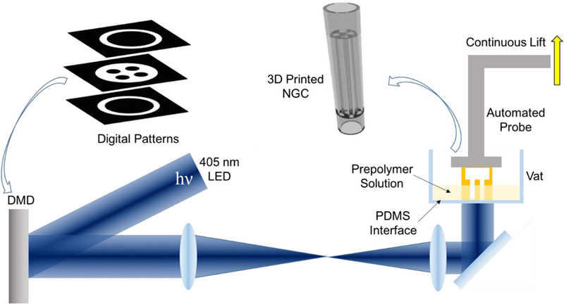
Schematic of the rapid continuous 3D-printing system for printing customizable NGCs.
One key component to achieve continuous printing is the polydimethylsiloxane (PDMS) substrate located on the bottom of the vat that directly interfaces with the prepolymer solution. The high gas permeability and porous nature of PDMS has been proven to induce oxygen inhibition of free radical polymerization (e.g., photopolymerization), leading to a thin uncrosslinked prepolymer layer between the PDMS surface and the polymerized parts [25]. Previously a Teflon film has been used to achieve the same oxygen inhibition layer for continuous liquid interface production [26]. Compared to the Teflon film, PDMS is much more cost effective and accessible for researchers. Most importantly, the soft nature of the Teflon film can cause meniscus deformation of the printing window during the continuous lifting of the polymerized parts, thus compromising the printing quality and limiting the feasible area of the printing window. In contrast, PDMS can be easily coated, cured or bonded onto any vat surface geometry, which allows for better integration. The smooth, immobile PDMS surface on the base of the rigid vat also prevents any deformation of the printing window.
By synchronizing the projected optical patterns with the continuous stage movements, smooth 3D constructs can be rapidly fabricated without interfacial artifacts that typically occur between droplets in the inkjet-based printers or lines in extrusion-based printers [22,20]. The elimination of such artifacts will greatly improve the homogeneity of the microstructure and, in turn, the mechanical integrity of the printed 3D objects, enabling complex designs that are normally hard to achieve with other manufacturing methods. Furthermore, the entire 3D-printing process is digitalized and controlled by a computer, which offers great reproducibility and flexibility to modify and optimize design parameters with significantly reduced turnaround time compared to traditional manufacturing methods (e.g., molding).
Continuous 3D printing of customizable NGCs
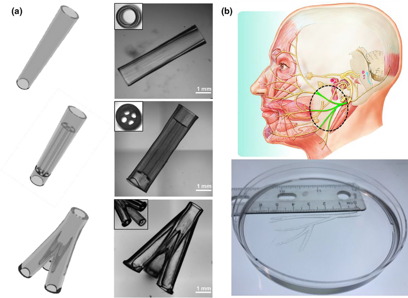
To demonstrate the printing capability of our rapid continuous 3D printer, we first printed a range of designer NGCs, including a simple hollow conduit, a conduit with multiple microchannels, a branched conduit, and an anatomically appropriate sized biomimetic conduit for human facial nerve repair (Figure 2). In Figure 2a, we show the CAD design of the NGCs on the left column and the 3D-printed NGCs on the right column. The top NGC design features a straight hollow conduit with a smooth surface and a wall thickness of 200 mm. In the middle NGC design, we incorporated four microchannels (400 mm in diameter, 4 mm in length) for the guidance of longitudinal nerve regeneration. Also, we integrated two hollow tubular sleeves (l mm in length) in a continuous fashion so that the proximal and distal ends of the cut nerves can be inserted into the sleeves to align with the microchannels. The fitted nerve ends could then be glued or sutured to the sleeves to secure the conduit in place. The bottom NGC design further demonstrated our capability to print branched conduits for nerve plexuses (e.g., one nerve splits into three branches). To demonstrate the scalability of our system to print large-scale biomimetic NGCs for human nerve repairs, we recapitulated the complex branched human facial nerve structure by printing an anatomically appropriate sized NGC (5.5 cm in length) featuring the zygomatic branches, the buccal branches, the marginal mandibular branch, and the cervical branch (Figure 2b). To the best of our knowledge, NGCs with such high complexity and large scale have never been achieved before. Owing to the nature of continuous projection printing, the NGCs in Figure 2a were printed within 2 min and the anatomically appropriate sized human facial NGC in Figure 2b was printed within 10 min, highlighting the unprecedented speed of our rapid 3D-printing platform.
FIGURE 2.
(a) Various NGC CAD designs (left column) and the corresponding 3D-printed NGCs (right column). (b) 3D-printed human life-size NGC; the facial nerve schematic on top was adapted from Atlas of Human Anatomy (p. 124, 6th Ed.), by F. H. Netter, 2014, Philadelphia, PA: Saunders. Copyright 2014 by Saunders, an imprint of Elsevier Inc. [27].
Tuning the mechanical property of the 3D-printed NGCs
Matching the mechanical properties of the NGC grafts to the host injury site is of great importance to prevent potential compression or laceration to the relatively soft regenerating nerves or failure in the implantation process [28–30]. The reported elastic modulus of the peripheral nerve tissue varies in a wide range from 0.5 MPa to 13 MPa, indicating the necessity of having the capability to fine-tune the mechanical property of the printed scaffold [3,31–33]. The photo-induced free radical polymerization mechanism underlying our 3D printer allows us to precisely control the mechanical properties via modulating the crosslinking density of the polymerized parts. Any material and fabrication parameters (light intensity, exposure time, photoinitiator concentration, material composition percentages, etc.) that affect the crosslinking density can be employed to tune the mechanical properties of the printed parts. To demonstrate the flexibility to tune the mechanical properties of the printed NGCs with our 3D printer, we defined three fabrication conditions with varying photoinitiator concentration and light intensity and evaluated the elastic modulus of the polymerized scaffolds printed by each condition (Figure 3). All other process and material parameters, such as printing speed, total printing time, and concentrations of gelatin methacrylate (GelMA) and poly(ethylene glycol) diacrylate (PEGDA), were kept constant for all three conditions.
FIGURE 3.
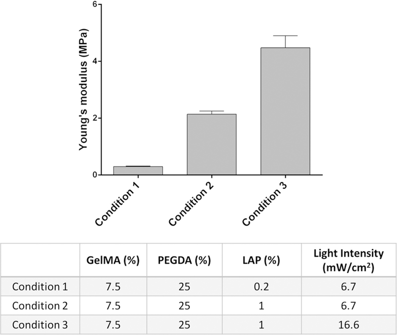
Young’s modulus of the 3D-printed constructs prepared with three different conditions.
We first prepared a prepolymer solution comprised of GelMA and PEGDA for printing the NGCs. GelMA is modified from denatured collagen to be photocrosslinkable and retains natural cell-binding motifs needed to support cellular adhesion, proliferation, and migration, thus making it a good candidate to promote guidance for regenerating axons [34–36]. The mechanical properties of GelMA hydrogels can readily be tuned by the degree of methacrylation and concentration of GelMA, as well as lightexposure intensity and time. However, the limited range of mechanical properties of GelMA leads to 3D scaffolds that are usually soft and fragile, which cannot provide the desired mechanical properties of NGC grafts. PEGDA has been used in many FDA-approved applications as it can be safely used in humans and is a well-known non-immunogenic biocompatible material resistant to bio-fouling and non-specific adsorptions in vitro and in vivo [37–40]. Also, the mechanical properties of the PEGDA hydrogel can be fine-tuned by the molecular weight and concentration of PEGDA, as well as the light-exposure intensity and time. Therefore, we incorporate PEGDA with GelMA to make a mechanically robust and tunable composite material that can meet the material requirements of NGC grafts and potentially promote axonal regeneration in vivo. We further synthesized lithium phenyl-2,4,6-trimethylbenzoylphosphinate (LAP) as the photoinitiator due to its great water solubility, high polymerization efficiency, and minimal cytotoxicity [41]. Moreover, LAP has significant absorbance at 405 nm, which allows for efficient polymerization with our printer, eliminating concerns related to UV damage.
As shown in the table in Figure 3, we kept the same concentration of GelMA and PEGDA across the three test conditions. Between conditions 1 and 2, only the concentration of the photoinitiator (LAP) was varied from 0.2% to 1%, which increased the Young’s modulus from 0.3 MPa to around 2 MPa. Between conditions 2 and 3, only the light-exposure intensity was increased from 6.7 mW/cm2 to 16.6 mW/cm2, which further increased Young’s modulus from around 2 MPa to 4.5 MPa. For the subsequent in vivo implantation, condition 2 was used to 3D print the NGCs with four microchannels to guide the sciatic nerve regeneration as a proof of concept. The material compositions and fabrication parameters can be further adjusted to cover a wider range of mechanical properties. With such flexibility to fine-tune the mechanical properties, as well as to adapt complex architecture designs, our rapid continuous 3D printer has demonstrated its capability to provide customizable NGCs with desirable geometries and material properties.
In vivo nerve regeneration guided by the 3D-printed NGCs
As previous work has demonstrated that microchannels integrated in the NGCs can improve nerve regeneration [3,14,42], we chose the NGC design with microchannels and sleeves (middle design in Figure 2a) as an example to assess the performance of our 3D-printed NGCs to guide nerve regeneration in vivo. These 3D-printed NGCs are 6 mm long in total with four linear microchannels (4 mm long) and two sleeves (1 mm long each). Complete sciatic nerve transection was performed on the transgenic mice expressing cyan fluorescent protein (CFP) under a neuron-specific (Thy-1) promoter. Following the transection, the proximal and distal ends of the nerves retracted, creating a nerve gap approximately 4 mm in distance. The 3D-printed NGCs were then immediately implanted to connect the proximal and distal nerve ends, which were aligned with the microchannels. Figure 4 presents the process of the surgical implantation and harvest in both bright field view and CFP view to highlight the nerve.
FIGURE 4.
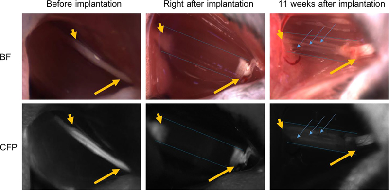
Intraoperative photographs of NGCs (bright field/CFP fluorescence) at the surgical nerve repair site. Immediately before implantation, the sciatic nerve is exposed approximately 1.5 cm at its exit from the pelvis (yellow arrow: proximal segment; yellow arrowhead: distal segment). Following transection and implantation of the NGC (blue dotted outlines), the proximal and distal segments of the sciatic nerve is delicately inserted into the NGC and secured into position with tissue glue. 11 weeks after implantation, the proximal segment of the nerve can be seen to connect through the microchannels within the NGC (blue arrow). Note: All images were obtained at the same magnification. Apparent differences in nerve and NGC sizes at different time points are due to the surgical orientation of the animal at the time of surgery.
Eleven weeks after the implantation, the NGC grafts were harvested and cryosectioned to evaluate the progress of the sciatic nerve regeneration in the NGCs. Hematoxylin and eosin (H&E) staining were first performed on sections at different locations from the proximal end of the NGC graft (0 mm) to the distal end (6 mm) (Figure 5). The regenerating nerves were observed to branch into the four microchannels from the proximal end and then merge into one nerve again at the distal end. Further-more, immunostaining with anti-neurofilament antibody (SMI 312) and abundant neurons were found across the entire length of the NGC graft (Figure 6).
FIGURE 5.
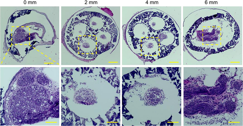
H&E staining of the sections of the regenerated sciatic nerve and the NGC with four microchannels at different locations from the proximal end to the distal end at 11 weeks post-implantation. Scale bars: 200 mm (top row), 100 mm (bottom row).
FIGURE 6.
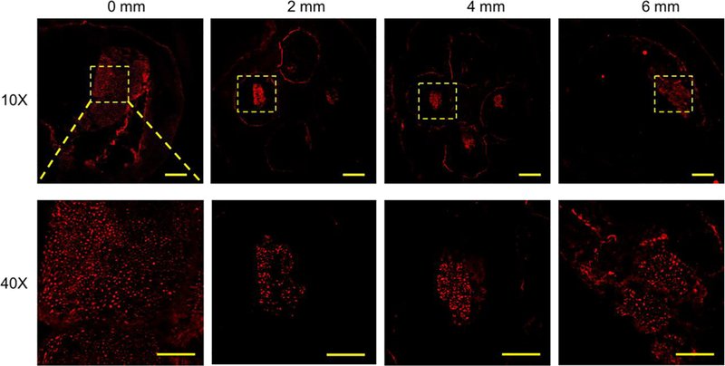
Confocal images of the sections of the regenerated sciatic nerve and the NGC with four microchannels at different locations from the proximal end to the distal end at 11 weeks post-implantation. SMI 312 was used to stain the neurofilaments. Scale bars: 200 mm (top row), 50 mm (bottom row).
Functional recovery tests
The functional recovery of the animals was assessed at Day 2, and Weeks 3, 7, and 10 post-operatively using the up-down method with the von Frey filaments to assess mechanical thresh-old and a modified Hargreaves test to assess thermal reactivity (Figure 7). The behavioral response measurement of the injured hind limbs implanted with NGCs (ipsilateral) was compared with that of the contralateral uninjured limbs. A normal response value for the von Frey test is 1.5–2.0 g, and a normal response value for the thermal test is 8–12 s. Both normal response zones are highlighted in gray in Figure 7a and b, respectively. The Day 2 tests were performed as the baseline for the functional recovery evaluation. As shown in Figure 7a and b, 2 days after implantation, all the ipsilateral legs of the animals did not have sensation due to complete transection of the sciatic nerve, thus exhibiting the maximum value for both the von Frey test (2.0 g) and the thermal test (20 s). This is also why there are no error bars for the 2-day test results of the ipsilateral legs. In the von Frey test (Figure 7a), the ipsilateral legs started to recover sensation within 3 weeks after the implantation and exhibited higher threshold values than the contralateral legs, which had lower threshold values than the normal response zone. The lower threshold values of the contralateral legs may be due to development of an allodynia over time, which is not entirely abnormal in a sciatic transection model. In the thermal test, the ipsilateral legs also started to recover sensation within 3 weeks and exhibit similar degrees of sensation compared to the contralateral legs (Figure 7b).
FIGURE 7.
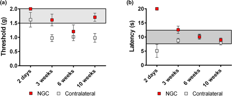
Functional recovery evaluation by (a) von Frey threshold testing and (b) thermal testing.
Discussion
In the past five years, a considerable number of efforts have been made to engineer NGCs as a potential alternative to the autograft for PNS injuries [7–11]. However, most of these engineered NGCs feature simple architectures that may not be sufficient to promote structural and functional recovery, especially in the case of longer nerve gaps (i.e., 15 mm or more in rodents or over 100 mm in humans). For instance, it has been demonstrated that conduits with a luminal filler or microchannels can significantly improve peripheral nerve regeneration compared to hollow conduits [14,42]. However, the luminal filler was prepared by a freeze-drying process, which offers limited control over the size and local distribution of the channels [42]. Micro-drilling has been also used to create more controlled microchannels within an agarose matrix, though it can only provide channels with limited length (below 1.5 cm) [14]. Therefore, an advanced biofabrication system is in great need for the manufacturing of complex NGCs. In this paper, we demonstrate in vivo implantation of our novel 3D-printed NGC with promising nerve regeneration and functional recovery.
3D-printing techniques have emerged as powerful manufacturing platforms to create tissue constructs and scaffolds with unprecedented flexibility and versatility, contributing to significant advancements in the tissue engineering and regenerative medicine field. While there are several distinct bioprinter setups based on different printing modalities (e.g., inkjet-based 3D printer, extrusion-based 3D printer, and DLP-based 3D printer), they are all driven by computers, and the printing processes are digitalized, enabling customized manufacturing of biological constructs (e.g., personalized NGCs for nerve injury repair), which may not be feasible with traditional manufacturing techniques. While nozzle-based printers (including both inkjet- and extrusion-based printers) have advantages in terms of simplicity and low entry cost, they also have inherent limitations. As nozzles are used to deposit the bio-ink in the extrusion-based bioprinting process, the resolution (i.e., the smallest printed feature size) is limited by the physical confinement of the nozzles, usually at or above 50 mm [20]. More importantly, the interfaces between the extruded lines of materials can significantly impact the overall structural integrity, especially for nerve repairs that require mechanical strength and compliance to withstand the adjacent muscle impact and displacement. In addition, as the nozzle-based printers deposit the material drop by drop or line by line in a serial fashion, it can be time consuming to print large-scale NGCs for large nerve gaps.
To address these challenges, we have developed a rapid continuous 3D printer based on the DLP technology, which prints by optically projecting patterned, 2D planes onto the prepolymer solution to photopolymerize the exposed area. Continuous printing of 3D objects with smooth contours can be realized by continuously altering the projected optical patterns and lifting the printed part from the printing plane vertically [24,26]. Compared to the raster-scanning process of the extrusion-based 3D printers, the DLP-based 3D printers can offer superior printing resolution, speed, and scalability, as well as excellent mechanical integrity of the continuouslyprinted 3D objects. The flexibility of our 3D-printing system also enables us to study the effect of different structural designs of NGCs on guiding the nerve repair. For instance, we can readily alter the number and size of the microchannels within the NGCs and investigate their influence on the regeneration rate and functional recovery. Lastly, as individual pixels of the micromirror array can be switched on and off rapidly for a percentage of time throughout the fabrication process, devices with spatiallycontrolled mechanical properties (e.g., stiffness) can be printed via the spatiotemporal control of pixel-level light exposure.
Although we chose a composite material consisting of GelMA and PEGDA to print the NGCs in this work, other types of photopolymerizable biomaterials (e.g., glycidyl methacrylate-hyaluronic acid) can also be readily implemented in our 3D-printing platform to create NGCs with desired material properties [15]. Such flexibility in tuning the material compositions and fabrication parameters allows easy control of the mechanical property and degradability of the 3D-printed scaffolds for the optimal performance. On top of that, since our 3D-printing technique employs the photopolymerization of an aqueous biomaterial solution by harmless visible light, cells (e.g., neural stem cells and Schwann cells) and growth factors (e.g., nerve growth factor) can be directly printed with the biomaterials and precisely localized to desired regions within the NGC to enhance nerve regeneration and achieve better functional outcomes.
Conclusion
In summary, we have developed a rapid continuous 3D-printing platform to create customizable NGCs featuring intricate architectures, as well as tunable material properties. Using the concepts of projection printing (instead of point-by-point writing) and continuous fabrication, our printing technique is simple, fast, and capable of 3D scaffold fabrication from any digital images (e.g., CAD design, MRI, and CT scans). Various NGC designs have been demonstrated with unprecedented speed and excellent mechanical integrity by our continuous printing method. The printed NGCs are composed of biocompatible materials and are capable of guiding the directional regeneration of sciatic nerves in vivo in rodents with motor and sensory recovery of function, underscoring the potential clinical applications in peripheral nerve repair.
Material and methods
3D printing of NGCs
PEGDA (Mn = 700) was purchased from Sigma–Aldrich (USA). GelMA and LAP were synthesized as described in the previous work [38,43]. The prepolymer solutions were prepared by dissolving GelMA, PEGDA, and LAP in Dulbecco’s phosphate-buffered saline (DPBS) following the recipes (wt.%) listed in the table of Figure 3. The 3D printer setup shown in Figure 1 is used to print all NGCs as well as the mechanical test samples. The NGCs were first designed in CAD software (Autodesk 3ds Max) and the 3D models were then sliced by a Matlab script to generate the digital patterns. The digital patterns were uploaded to the DMD chip in sequential order and used to selectively expose the prepolymer solution for continuous printing. The DMD chip used in the setup is the DLP® LightCrafter™ 9000 Evaluation Module (Texas Instruments).
Mechanical measurement
The elastic modulus of the bulk hydrogel was determined via unconfined compression testing (Univert, CellScale) using cylindrical specimens (D = 2 mm, L = 2 mm, N = 3) at room temperature. The specimens were incubated in DPBS solution at 37 °C overnight before testing to ensure swelling equilibration. The elastic modulus per specimen was calculated from the linear region of the stress–strain curve.
NGC implantation
Male and female transgenic mice expressing Cyan Fluorescent Protein (CFP) under the control of a neuron-specific (Thy-1) promoter were evaluated. The 6 mm long NGC was surgically implanted to contain the disconnected distal and proximal nerve ends, and surgical glue was used to hold the two nerve ends in the conduit. Twelve mice were implanted with the NGCs featuring microchannels and sleeves into their left hind limbs to connect the transected nerve ends. All mice underwent sterile surgeries under general anesthesia with 1:1 cocktail of ketamine:midazolam. Because the proximal and distal ends of the nerves retract following transection, the total distance of nerve regeneration was approximately 4 mm.
von Frey threshold testing
Mechanical withdrawal thresholds were assessed at 3, 7, and 10weeks post-operatively using the up-down method [44]. Briefly, animals were placed in a clear, plastic, wire mesh-bottomed chamber for 45min prior to the initiation of testing. Tactile thresholds were measured with a series of von Frey filaments (Seemes Weinstein von Frey esthesiometer; Stoelting Co., Wood Dale, IL, USA) ranging from 2.44 to 4.31 (0.04–2.00 g) applied to the plantar surface of each hindpaw. The 50% probability of withdrawal threshold was recorded individually for the left and right hindlimbs.
Thermal testing
At 3, 7, and 10weeks post-surgery, hindpaw withdrawal latencies were assessed using a modified Hargreaves device (University Anesthesia Research and Development Group, Department of Anesthesiology, University of California, San Diego). Prior to the initiation of testing, mice were acclimated in clear Plexiglas containers on a glass surface maintained at 30 °C for 45 min. When mice were no longer showing exploratory behaviors, a calibrated, thermal stimulus was applied to the plantar surface of the hindpaw, and the latency-to-withdrawal of the paw was recorded. Latency-to-withdrawal was recorded three times per paw with a minimum of 2min between stimulus applications. A cutoff time of 20 s was used to prevent tissue damage. Withdrawal latency is reported as a mean ± SEM.
NGC harvesting
At 11 weeks post-operation, the surgical sites were opened, and the regenerated sciatic nerves and the NGCs were imaged with the mice under general anesthesia. The conduits with the regenerated nerve inside were then harvested. The harvested samples were embedded in the optimal cutting temperature (OCT) compound and snap frozen in liquid nitrogen. The mice were sacrificed at the end of the study. The frozen samples were stored at —80 °C until they were cryosectioned at a thickness of 10 μm.
Histology, immunofluorescence staining, and image acquisition
To perform the hematoxylin and eosin (H&E) staining, the sections from the cryosectioning were first fixed in 10% formalin (Fisher Scientific) for 30 min at room temperature followed by rinsing with deionized water. The sections were then stained with Gill No. 2 hematoxylin (Sigma–Aldrich) and eosin (Sigma–Aldrich). The stained sections were mounted with coverslips for imaging. Histology images were taken by a Keyence BZ-9000 microscope (Keyence) with multicolor CCD camera.
To perform the immunofluorescence staining, the sections were first fixed in 4% paraformaldehyde (Electron Microscopy Sciences) for 1 min at room temperature and then blocked with 0.1% Triton X-100 (Sigma–Aldrich), 1% bovine serum albumin (BSA, Fisher Scientific), and 9% normal goat serum (Life Technologies) for 30 min at room temperature. To prevent the nonspecific binding of the secondary antibody, the sections were blocked by goat anti-mouse IgG (H+L) (1:100, Abcam) for 2 h at 4 °C. The sections were then stained with the anti-neurofilament antibody SMI 312 (1:1000, Biolegend) overnight at 4 °C followed by another blocking session with 0.1% Triton X-100 (Sigma– Aldrich), 1% bovine serum albumin (BSA, Fisher Scientific), and 9% normal goat serum (Life Technologies) for 30 min at room temperature. Alexa Fluor® 555 goat anti-mouse IgG (H+L) (1:1000, Invitrogen) was applied to the sections as the secondary antibody for 2 h at 4 °C. The sections were then mounted with coverslips and imaged by a Leica SP5 confocal microscope (Leica microsystems) at 10× and 40×.
Acknowledgments
The work was supported in part by grants from the National Institutes of Health (R21HD090662, R01EB021857) and National Science Foundation (CMMI-1547005 and CMMI-1644967) to S.C. and a grant from National Institutes of Health (1TL1TR001443) to K.R.T. The UCSD Neuroscience Microscopy Shared Facility was supported by Grant P30 (NS047101). We thank Laarni Gapuz for the help with cryosectioning and H&E staining.
References
- [1].Kehoe S, Zhang XF, Boyd D, Injury 43 (2012) 553–572. [DOI] [PubMed] [Google Scholar]
- [2].Ichihara S, Inada Y, Nakamura T, Injury 39 (2008) 29–39. [DOI] [PubMed] [Google Scholar]
- [3].Dinis TM et al. , J. Mech. Behav. Biomed. Mater 41 (2015) 43–55. [DOI] [PubMed] [Google Scholar]
- [4].Bellamkonda RV, Biomaterials 27 (2006) 3515–3518. [DOI] [PubMed] [Google Scholar]
- [5].Kim YT et al. , Biomaterials 29 (2008) 3117–3127. [DOI] [PMC free article] [PubMed] [Google Scholar]
- [6].Hu Y et al. , Sci. Rep 6 (2016) 32184. [DOI] [PMC free article] [PubMed] [Google Scholar]
- [7].Gu X, Ding F, Williams DF, Biomaterials 35 (2014) 6143–6156. [DOI] [PubMed] [Google Scholar]
- [8].Mobini S et al. , Curr. Opin. Biomed. Eng 4 (2017) 134–142. [Google Scholar]
- [9].Belanger K et al. , Macromol. Biosci 16 (2016) 472–481. [DOI] [PubMed] [Google Scholar]
- [10].Faroni A et al. , Adv. Drug Deliv. Rev 82 (2015) 160–167. [DOI] [PubMed] [Google Scholar]
- [11].Lackington WA et al. , Sci. Eng 3 (2017) 1221–1235. [DOI] [PubMed] [Google Scholar]
- [12].Belkas JS, Shoichet MS, Midha R, Neurol. Res 26 (2004) 151–160. [DOI] [PubMed] [Google Scholar]
- [13].Pateman CJ et al. , Biomaterials 49 (2015) 77–89. [DOI] [PubMed] [Google Scholar]
- [14].Shahriari D et al. , J. Biomed. Mater. Res. – Part A 105 (2017) 3392–3399. [DOI] [PMC free article] [PubMed] [Google Scholar]
- [15].Suri S et al. , Biomed. Microdevices 13 (2011) 983–993. [DOI] [PMC free article] [PubMed] [Google Scholar]
- [16].Fozdar DY et al. , Int. J. Nanomed 6 (2011) 45–57. [Google Scholar]
- [17].Fozdar DY et al. , Biofabrication 2 (2010) 35005. [DOI] [PMC free article] [PubMed] [Google Scholar]
- [18].Soman P et al. , Biomed. Microdevices 14 (2012) 829–838. [DOI] [PMC free article] [PubMed] [Google Scholar]
- [19].Johnson BN et al. , Adv. Funct. Mater 25 (2015) 6205–6217. [DOI] [PMC free article] [PubMed] [Google Scholar]
- [20].Zhu W et al. , Curr. Opin. Biotechnol 40 (2016) 103–112. [DOI] [PubMed] [Google Scholar]
- [21].Zhu W et al. , Biomaterials 124 (2017) 106–115. [DOI] [PMC free article] [PubMed] [Google Scholar]
- [22].Zhang AP et al. , Adv. Mater 24 (2012) 4266–4270. [DOI] [PMC free article] [PubMed] [Google Scholar]
- [23].Lu Y et al. , J. Biomed. Mater. Res. A 77 (2006) 396–405. [DOI] [PubMed] [Google Scholar]
- [24].Zhu W et al. , Adv. Mater 27 (2015) 4411–4417. [DOI] [PMC free article] [PubMed] [Google Scholar]
- [25].Dendukuri D et al. , Macromolecules 41 (2008) 8547–8556. [Google Scholar]
- [26].Tumbleston JR et al. , Science (80-) 347 (2015) 1349–1352. [DOI] [PubMed] [Google Scholar]
- [27].Netter FH, Atlas of Human Anatomy Sixth, 6th ed., Saunders, 2014. [Google Scholar]
- [28].Salacinski HJ et al. , J. Biomater. Appl 15 (2001) 241–278. [DOI] [PubMed] [Google Scholar]
- [29].Taylor M et al. , J. Mater. Sci. Mater. Med 10 (1999) 841–846. [DOI] [PubMed] [Google Scholar]
- [30].Tsai EC et al. , J. Neurotrauma 21 (2004) 789–804. [DOI] [PubMed] [Google Scholar]
- [31].Borschel GH et al. , J. Surg. Res 114 (2003) 133–139. [DOI] [PubMed] [Google Scholar]
- [32].Zilic L et al. , J. Anat 227 (2015) 302–314. [DOI] [PMC free article] [PubMed] [Google Scholar]
- [33].Kwan MK et al. , Acta Orthop. Scand 63 (1992) 267–272. [DOI] [PubMed] [Google Scholar]
- [34].Nichol JW et al. , Biomaterials 31 (2010) 5536–5544. [DOI] [PMC free article] [PubMed] [Google Scholar]
- [35].Grogan SP et al. , Acta Biomater 9 (2013) 7218–7226. [DOI] [PMC free article] [PubMed] [Google Scholar]
- [36].Cha C et al. , Biomater. Sci 2 (2014) 703–709. [DOI] [PMC free article] [PubMed] [Google Scholar]
- [37].Yañez-Soto B et al. , J. Biomed. Mater. Res. Part A 101A (2013) 1184–1194. [DOI] [PMC free article] [PubMed] [Google Scholar]
- [38].Qu X et al. , Biomaterials 34 (2013) 9812–9818. [DOI] [PMC free article] [PubMed] [Google Scholar]
- [39].Gou M et al. , Nat. Commun 5 (2014) 3774. [DOI] [PMC free article] [PubMed] [Google Scholar]
- [40].Xue P et al. , RSC Adv 5 (2015) 75204–75209. [Google Scholar]
- [41].Fairbanks BD et al. , Biomaterials 30 (2009) 6702–6707. [DOI] [PMC free article] [PubMed] [Google Scholar]
- [42].Lee J-Y et al. , J. Bone Jt. Surgery-American 94 (2012) 2084–2091. [DOI] [PubMed] [Google Scholar]
- [43].Soman P et al. , Biotechnol. Bioeng 110 (2013) 3038–3047. [DOI] [PMC free article] [PubMed] [Google Scholar]
- [44].Chaplan SR et al. , J. Neurosci. Methods 53 (1994) 55–63. [DOI] [PubMed] [Google Scholar]


