Abstract
Objective:
Using synchronized three-dimensional stage translation and multiangle radiation delivery to improve conformality and homogeneity of radiation delivery to complexly shaped target volumes for precision preclinical radiotherapy.
Methods:
A CT image of a mouse was used to design irradiation plans to target the spinal cord and an orthotopic lung tumour. A dose painting method is proposed that combines heterogeneous two-dimensional area irradiations from multiple beam directions. For each beam direction, a two-dimensional area was defined based on the projection of the target volume. Each area was divided into many single beam Monte Carlo simulations, based on radiochromic film characterization of a 2.4 mm beam of a commercial precision image-guided preclinical irradiation platform. Beam-on time optimization including all simulated beams from multiple beam directions was used to achieve clinically relevant irradiation objects. Dose painting irradiation plans were compared to irradiation plans using a fixed aperture and rotatable variable aperture collimator.
Results:
Irradiation plans for the proposed dose painting approach achieved good target coverage, similar dose to avoidance structures in comparison with irradiation using a rotatable variable aperture collimator, and considerably less dose to avoidance volumes in comparison with irradiation using a non-rotatable fixed aperture collimator. Required calculations and beam-on times were considerably longer for the dose painting method.
Conclusion:
It was shown that the proposed dose painting strategy is a valuable extension to increase the versatility of current generation precision preclinical radiotherapy platforms. More conformal and homogeneous dose delivery may be achieved at the cost of increased radiation planning and delivery duration.
Advances in knowledge:
More advanced radiation planning for image-guided preclinical radiotherapy platforms can improve target dose conformality and homogeneity with the use of optimized dynamic irradiations with synchronized couch translation. The versatility of these platforms can be increased without hardware modifications.
Introduction
The advent of image-guided preclinical radiation research platforms enables radiobiological studies that make use of more conformal and complex dose distributions, compared to previous-generation experiments. These modern platforms use photon energies and a geometrical millimetre-size scale required for preclinical precision irradiation.1,2 The hardware and software of current commercial preclinical research platforms have seen advances towards improving different aspects, including radiation delivery3 and dose planning.4–7
Preclinical studies to develop and assess novel treatment strategies with high potential for use in a clinical setting could benefit from more complex preclinical irradiation capabilities.8 Imaging modalities such as X-ray CT9 and bioluminescence10,11 can provide the basis for developing radiation delivery plans derived from online functional and anatomical imaging. The increased interest and use of orthotopic tumour models instead of subcutaneous tumour models increases the demand for more sophisticated irradiation planning and delivery.12
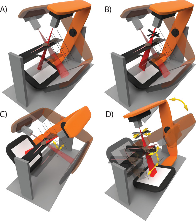
The technological development of preclinical image-guided radiation research platforms could be divided into four categories with different degrees of freedom for radiation delivery as shown in Figure 1. Current state-of-the-art for precision preclinical irradiation is in the transition from Type A to Type B. In comparison with a set of fixed aperture size collimators, beam shape modulation could improve conformality of precision irradiation, but is challenging at the required spatial scale of about 1 mm to several cm. Beam sizes down to 1 mm or smaller are difficult to model and deliver accurately using fixed aperture beam collimation.3,13 Whereas the clinical approach of using multileaf beam collimation is not feasible, iris and jaw collimation techniques have been attempted.14–16 While these approaches are interesting, they are challenging to implement robustly for mm-sized fields, remain unvalidated in literature and are therefore currently not practically applicable. Other available degrees of freedom could be more promising for implementation with current hardware. For example, modulation of beam energy and current, in combination with stage translation and gantry rotation during irradiation.
Figure 1.
The technological development of image-guided small animal radiation research platforms can be roughly divided into four categories: (A) three-dimensional translation of the animal and gantry rotation are used to perform step-and-shoot wise irradiations in static geometrics. Different beam sizes can be delivered using manually interchangeable collimators. (B) Radiation can be delivered using any rectangular beam size with variable aperture collimators. Irradiation delivery remains restricted to step-and-shoot treatments. (C) Irregularly shaped, conformal, radiation delivery is enabled by animal translation during irradiation in a dynamic fashion using a fixed beam size. Multiple beam directions can be combined into a single irradiation plan. (D) The collimator aperture, gantry angle, animal couch position and angle, and possibly other degrees of freedom such as dose rate, are applied dynamically during irradiation. In all illustrations, semi-transparent elements indicate different states of static step-and-shoot irradiations and yellow arrows indicate movement of the animal couch and beam collimators during radiation delivery.
The purpose of this study is to demonstrate the feasibility of Type C irradiation delivery as shown in Figure 1. Synchronized three-dimensional stage translation and radiation delivery from multiple radiation directions are used to improve conformality of radiation delivery to a complexly shaped target volume. We developed algorithms to create irradiation plans that we simulated using a validated Monte Carlo (MC) model of the preclinical radiotherapy research platform.4
methods and materials
Radiation delivery and planning
A preclinical research platform X-RAD 225Cx (Precision X-ray, North Branford, CT) was used for CT image guidance and radiation delivery.17 A 225 kVp 1.1 (C1) and 2.4 (C2) mm diameter beam were used as defined at the isocentre by the full width at half maximum (FWHM). A research version of the dedicated small animal radiotherapy planning system SmART-ATP (v. 1.1, SmART Scientific Solutions BV, Maastricht, Netherlands) was used for radiation planning on a 16 core Intel Core i9-7960X. SmART-ATP uses a validated MC model4 that was calibrated to the specific dosimetric output of the irradiator. Further irradiation details following the ESTRO ACROP guidelines can be found in Supplementary Material 1 (A).18
Dynamic irradiation
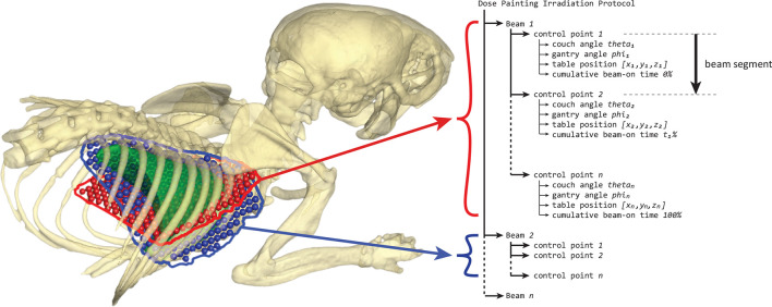
SmART-ATP was extended to create the proposed dynamic radiation delivery methods. The X-RAD225Cx enables radiation delivery specification using a control point sequence, similar to clinical radiation delivery plans for linear accelerators. The treatment protocol specifies values for all degrees of freedom of the irradiator at specific control points. A treatment protocol specifies one or multiple beams that each consist of at least two control points. Radiation is delivered during beam segments that are defined by two adjacent control points. The delivered dose of a beam segment is specified with cumulative beam-on time. This structure of radiation delivery by control point specification is illustrated in Figure 2.
Figure 2.
An example of a dose painting irradiation protocol structure consisting of two beams at a different gantry angle. The irradiation protocol can consist of multiple beams with each beam consisting of at least two control points. X-rays are turned on at the start of a beam and turned off at the last control point, during which the couch is translated to paint a two-dimensional area. By using beam-on time optimization and combining multiple radiation directions during optimization, each two-dimensional area can deliver a heterogeneous dose distribution to the target volume to optimize plan quality.
By interpolation of the degrees of freedom of the irradiator, a dynamic irradiation can be performed. Currently, the irradiator cannot interpolate specimen stage positions between adjacent control points. Therefore, continuous stage translation was mimicked by using sufficiently small beam segment that use spatially and temporally proximate control points.
To create conformal dynamic irradiation protocols, couch and gantry angle pairs were selected manually. Irradiation protocol creation was divided into multiple two-dimensional area irradiation problems (the red and blue regions in Figure 2). For each photon incident direction, a couch and gantry angle pair, a beam consisting of many control points is created. The couch rotation angle around a vertical axis is fixed at 0° degrees for the X-RAD225Cx used in this study.
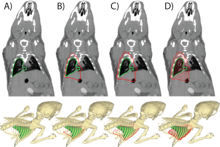
For each beam direction, the delineated target volume is projected onto a virtual plane perpendicular to the beam. The projection plane is positioned such that it intersects the centre of mass of the target volume which was calculated assuming a homogeneous target volume density. The two-dimensional target region for the beam direction was calculated as the outer contour of the target volume projection. This outer contour was enlarged with the diameter of the radiation beam to ensure complete target coverage. Absolute positions for the control points were calculated at an equidistance of 0.75 mm, see Supplementary Material 1 (B), in a hexagonal grid pattern within the outer contour. Finally, a radiation beam is simulated at each control point. MC simulations for dose painting irradiations were performed to reach 100k photon histories per square millimetre, to achieve a cumulative statistical uncertainty of at least 3% for each beam direction. The creation of the simulation grid for a target volume is illustrated in Figure 3.
Figure 3.
The dose painting approach for irradiators of type C as shown in Figure 1. An example is shown for the calculation of irradiation grid positions to irradiate the whole right lung of a mouse from a single anterior beam direction. (A) The target volume delineation to create the irradiation plan. (B) A projection outline of the target volume is calculated onto a virtual plane perpendicular to the beam that intersects at the centre of mass of the target volume. (C) A margin is added to the projected area to assure target coverage. (D) An irradiation grid for the dose calculations is created, which will be used to calculate beam-on times to deliver a specific dose to the target volume at each grid point. Multiple couch and gantry angle pairs can be combined into an irradiation plan.
Dose measurement
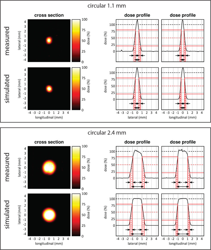
Beams were characterized spatially and dosimetrically with radiochromic film positioned at 5 mm depth between solid water slabs, at the isocentre of the irradiator, and irradiated for 120 s. Additional details about the radiochromic film calibration and analysis are provided in Supplementary Material 1 (C). Beam dimensions were defined as the FWHM for the lateral and longitudinal direction. Dose rates were defined as the average in an area of 50% to the maximum dose rate. Beam penumbra sizes were defined as the dose gradient required to cover 20 to 80% of the maximum dose.
Irradiation cases
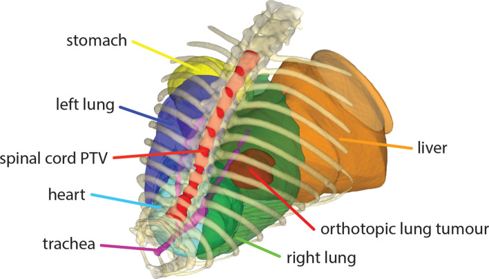
Two irradiation scenarios were used based on a cone beam CT image of a mouse with an orthotopic lung tumour. The image was acquired at sufficient resolution and reconstructed to an isotropic voxel spacing of 0.1 mm. A radiation oncologist delineated the orthotopic lung tumour, both lungs, heart, spinal cord, liver, stomach and trachea, see Figure 4. The orthotopic lung tumour was targeted for Case 1 and a length of 15 mm of the spinal cord was targeted for Case 2. Irradiation protocols were created to deliver an arbitrary prescription dose of 10 Gy to the target volume. No treatment margins were used for sub clinical disease spread or uncertainties in radiation delivery. Therefore, the planning target volume (PTV) was equal to the gross tumour volume (GTV) and dose was planned to the PTV.
Figure 4.
An overview of delineated volumes of interest that were considered together with a part of the mouse skeleton for relative spatial reference. Both lungs, the heart, stomach, liver and trachea were included as avoidance regions. The orthotopic lung tumour and a 15 mm long part of the spinal cord were considered as target volumes for two irradiation cases.
Tissue segmentation was performed starting with 2 Hounsfield Unit (HU) thresholds at −700 and 1200 to segment air, soft tissue and bone. Thereafter, the left and right lung delineations were used to override the threshold-based segmentation to define lung tissue. For both cases, plans were created for irradiations using a fixed aperture collimator, rotatable variable aperture collimator (RVAC), and for the proposed dose painting approach. For Case 1, four gantry angles were selected in the anterior, posterior, lateral and medial direction at 90° offsets. For Case 2, two parallel opposed lateral gantry angles were selected. For all simulations, an isotropic dose simulation grid resolution of 0.2 mm was used.
Irradiation plans for the fixed aperture irradiations were created using the smallest beam sizes available for the X-RAD225Cx which are large enough to achieve complete target coverage. For Case 1, this was a circular 5 mm diameter field and for Case 2, this was a square 20 × 20 mm field, defined as the FWHM at the isocentre. The RVAC plans were created using optimal custom rotation and aperture sizes. Collimator rotations were determined by calculating the angle of the longest direction of the minimum volume enclosing ellipsoid for the target volume, using a solver based on the Khachiyan algorithm.19 The dose painting irradiation plans resulted in a total of 256 beams for Case 1 for the four gantry angles combined, and a total of 280 beams for Case 2.
Beam-on time optimization
All irradiation plans were required to achieve a D95% and V95% of 100%. For Case 1, beam-on times for all three irradiation methods were calculated using the beam-on time optimization framework as described in Balvert et al..5 The lung tumour PTV was set as target volume, and the heart, left lung and spinal cord were considered as avoidance volumes with optimization weights of 0.4, 0.3 and 0.3, respectively. The minimum and maximum dose were constrained to 95 and 120% of the prescription dose with a minimum mean target dose of 10 Gy as constraint. Multiple optimization iterations were performed to minimize the dose to avoidance volumes. Optimization for the dose painting method for Case 1 was performed at a downscaled isotropic voxel resolution of 0.5 mm to speed up optimization calculations. All beams from the four gantry angles were included simultaneously in the optimization.
For Case 2, beam-on times for the fixed aperture and RVAC irradiation plans were linearly scaled to achieve the D95% and V95% of 100% with minimal total dose and a mean target dose of at least 5 Gy delivered from each of the two gantry angles. Beam-on times for the dose painting method for Case 2 were calculated using the beam-on time optimization framework using the same weights and constraints as for Case 1. Beam-on time optimizations for Case 2 were performed at the full isotropic dose voxel resolution of 0.2 mm, but for each gantry angle separately such that a minimum mean dose of 5 Gy was delivered from each beam direction.
When resulting beam-on times of the optimization framework did not fully satisfy the requirement of a D95% of 100%, beam-on times of all beams were increased linearly with the same factor to satisfy that requirement.
Results
Beam characterization
Figure 5 shows dose profiles, beam dimensions and beam penumbras extracted from two-dimensional dose images from the radiochromic film measurements of collimator C1 and C2. Average beam dimensions were measured to be 1.1 and 2.4 mm FWHM. Average beam penumbra sizes for the longitudinal and lateral direction were 0.4 and 0.5 mm for C1 and C2, respectively. For C1, an average dose rate of 0.18 cGy/mAs was measured in an area of 0.9 mm2. For C2, an average dose rate of 0.29 cGy/mAs was measured in an area of 4.5 mm2. This makes the irradiated area of C1 81% smaller than C2, with a 38% lower absolute dose rate. Combined, to paint a dose in the same volume treatment, the irradiation delivery time is 8.4 times higher when using C1 compared to C2.
Figure 5.
Two-dimensional beam characterization of the top (1.1) and bottom (2.4) mm beam using radiochromic film measurements and MC simulations. The irradiated area of the 1.1 mm beam is 81% smaller and has a 38% lower absolute dose rate in comparison with the 2.4 mm beam.
Irradiation cases
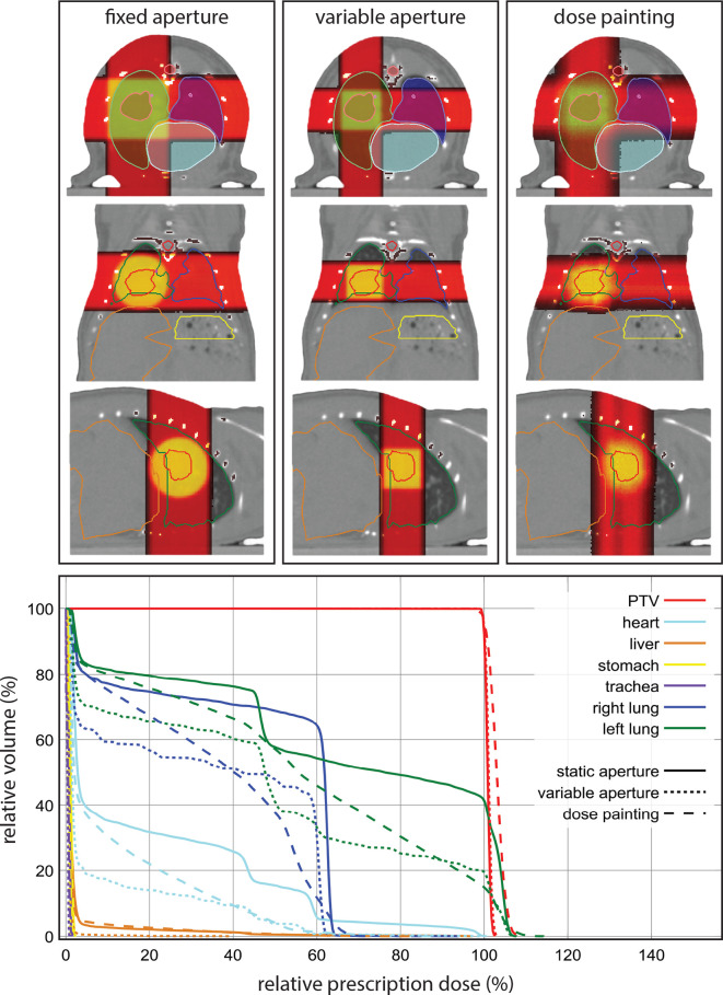
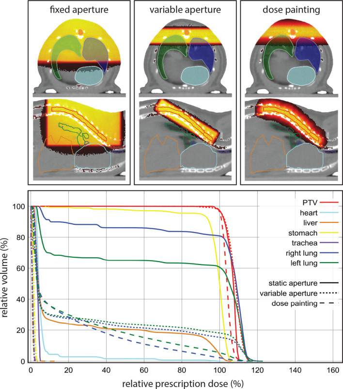
The duration of the different phases of the radiation planning process and the number of simulated beams are shown in Table 1. Radiation simulation for the dose painting method for both cases required considerably longer in comparison with the fixed aperture and RVAC methods, with about half of the time spent on data processing. The total CPU time for the simulation of a single beam for the dose painting approach on a single physical CPU was 4–5 s for both cases. The time required to calculate the simulation setup was about 8 s for the dose painting method for both cases, and a negligible amount time was needed to calculate the beam size and collimator rotation for the RVAC simulation setups. A few minutes were spent on the complete beam-on time optimization process, with single optimization iterations taking less than 1 min for all cases. Good target coverage was achieved for all plans with sharp cumulative DVHs for both cases and all irradiation methods, see Figures 6 and 7. The circular 2.4 mm beam was used for all irradiations using the dose painting method.
Table 1.
The durations of different stages of the radiation delivery and planning process in seconds. Beam-on times were calculated for a beam current of 13 mA. MC simulations were run with parallel threads and performed to reach 100k photon histories per square millimetre. For the fixed aperture and RVAC methods for Case 2, the beam-on times were scaled to achieve a D95% and V95% of 100% with minimal total beam-on time, and each beam angle delivering at least 5 Gy to the target volume, without requiring the beam-on time optimization framework. The durations for the optimization indicate the time required for a single optimization iteration. For the complete optimization of the irradiation plans, a few optimization iterations were required
| Case 1 | Case 2 | |||||
| Fixed aperture | Variable aperture | Dose painting | Fixed aperture | Variable aperture | Dose painting | |
| Number of simulated beams (-) | 4 | 4 | 256 | 2 | 2 | 280 |
| Anterior | 1 | 1 | 68 | - | - | - |
| Posterior | 1 | 1 | 61 | - | - | - |
| Lateral left | 1 | 1 | 66 | 1 | 1 | 140 |
| Lateral right | 1 | 1 | 61 | 1 | 1 | 140 |
| Total dose calculation (s) | 107 | 64 | 1377 | 160 | 58 | 1556 |
| Parallel MC simulations | 73 | 38 | 633 | 132 | 33 | 749 |
| Data import | 11 | 11 | 648 | 5 | 5 | 710 |
| Data processing | 23 | 15 | 96 | 23 | 20 | 97 |
| Single optimization iteration (s) | 14 | 15 | 59 | - | - | 15 |
| Total beam-on time (s) | 224 | 229 | 1587 | 221 | 238 | 1954 |
| Anterior | 58 | 64 | 361 | - | - | - |
| Posterior | 39 | 38 | 478 | - | - | - |
| Lateral left | 79 | 78 | 358 | 111 | 120 | 977 |
| Lateral right | 49 | 49 | 378 | 110 | 118 | 977 |
MC, monte carlo.
Figure 6.
At the top an overview of the resulting dose distributions for the fixed aperture, RVAC and dose painting irradiation approaches for the irradiation of an orthotopic tumour in the right lung. Below the resulting cumulative dose volume histograms for all volumes of interest for all three irradiation methods. PTV, planning target volume; RVAC, rotatable variable aperture collimator.
Figure 7.
At the top an overview of the resulting dose distributions for the fixed aperture, RVAC and dose painting irradiation approaches for the irradiation of a part of the spinal cord from two parallel opposed lateral radiation incident directions. Below the resulting cumulative dose volume histograms for all volumes of interest for all three irradiation methods. PTV, planning target volume; RVAC, rotatable variable aperture collimator.
Orthotopic lung tumour irradiation
The optimizer excluded 44 beams from the final dose painting plan. The smallest available fixed aperture collimator to achieve complete target coverage was an 8 mm diameter beam. A 5 × 5 mm square beam was used for the RVAC method at a collimator rotation of 0°. The increased conformality of the RVAC and dose painting method resulted in considerably lower doses to the left lung, trachea and heart in comparison with the fixed aperture irradiation, see Figure 6. The dose painting method resulting in a slightly lower dose homogeneity in the PTV.
Spinal cord irradiation
The optimizer excluded 37 beams from the final dose painting plan. The smallest available fixed aperture collimator to achieve complete target coverage was a 20 × 20 mm square beam. For the RVAC irradiation, the calculated collimator aperture was 3.5 × 14.8 mm to achieve a beam size of 4.3 × 17.5 mm at the isocentre of the irradiator, positioned at a collimator angle of 149° relative to the horizontal longitudinal direction of the irradiator (into the gantry). The dose painting method resulted in a slightly better dose homogeneity in the target volume than the fixed aperture and RVAC method, see Figure 7. The fixed aperture irradiation resulted in considerably higher doses being delivered to all avoidance volumes. The dose painting method achieved the best conformality, with a slightly larger volume of low doses to the left and right lung, but considerably lower volume of higher dose to both lungs.
Discussion
In this study, the feasibility of a dose painting strategy that makes use of synchronized stage translation and irradiation was shown, using a dedicated small animal radiation planning system and irradiator. For the irradiation cases discussed, the dose painting method produces irradiation plans with good target volume coverage, similar dose to avoidance volumes in comparison with irradiation using a RVAC at optimal angle and beam aperture, and considerably less dose to avoidance volumes in comparison with irradiation using a non-rotatable fixed aperture collimator.
The dose painting method can achieve superior conformality at the expense of increased radiation planning and delivery duration. With the use of suitable advanced software and user interface, radiation planning for the dose painting method is not considerably more complicated and can be applied using current generation image-guided preclinical irradiation platforms. In comparison with the use of a RVAC, the proposed dose painting method including the beam-on time optimization takes the local tissue environment into account based on MC simulations, to enable fine heterogeneous dose delivery throughout the target volume, either to improve target dose homogeneity, see Figure 7, or to enable three-dimensional heterogeneous volumetric target dose irradiation when radiation planning software would enable this.
Variable aperture collimators enable the selection of optimal beam sizes and relieves the user from manual collimator placement, which is relatively prone to errors and time consuming as the gantry may need to rotate to a specific angular range to allow collimator exchange. However, the implementation of variable aperture collimators requires thorough validation for mechanical stability and radiation leakage, especially at the small beam sizes used in precision preclinical radiotherapy. To our knowledge, the use of variable aperture collimators for preclinical image guided radiotherapy remains unvalidated in the literature, which makes the proposed dose painting method an excellent candidate to improve plan conformality using current generation hardware.
The main disadvantage of the dose painting method is the increased radiation delivery duration, see Table 1, which ultimately concerns the trade-off between larger beam sizes that offer higher dose rates but lower spatial frequencies, and smaller beam sizes that enable smaller dosimetric feature sizes but increase total beam-on time.7 A side-effect of increased irradiation duration is the increased proneness to motion errors. The use of multiple collimator apertures or a RVAC in combination with the proposed dose painting method could improve the overall dose rate while minimizing impact to dose conformality. Preferably, the radiation beam size, and consequently maximum dose rate and achievable dose resolution, should be determined by the radiation planning system based on time and plan quality constraints, rather than by manual selection by the user.
Reducing beam sizes rapidly increases the irradiation duration because besides the smaller irradiated volumes, dose rates decrease rapidly. A reduction from a 2.4 to 1.1 mm beam, Figure 5, leads to a more than eight times higher required beam-on time. It is recognized that margin management for preclinical irradiations differs from clinical practice. For example, there may be no need to account for subclinical disease spread, but margins for motion and radiation targeting inaccuracies are still required. Considering common imaging resolutions and radiation targeting uncertainties for current generation hardware,1,3,17,20 and initial work on margins,21,22 a need to use smaller beam sizes than the 2.4 mm used in this study is not foreseen for the majority or preclinical irradiation studies.
Currently, the irradiator used in this study can be equipped with an X-ray tube rated up to 4500 W in combination with a sufficiently capable high voltage generator. This enables a beam current of 20 mA at 225 kVp instead of 13 mA used in this study and would decrease reported beam on times by a factor 1.5. Even higher achievable dose rates are not unlikely to become available for these platforms in the future.
The dose painting method currently requires more time for the radiation planning and calculation process. However, the total required number of simulated photon histories is similar to the requirements for a fixed aperture or RVAC simulation, but there is a much higher need for data processing. By relaxing requirements on statistical uncertainty for MC simulations from 3% used in this study to, e.g. 5%, calculation times can be reduced. With tighter process integrations and further software optimizations, data processing performance issues are not expected to withhold practical implementation of this approach.
The work of Stewart et al.6 resulted in a semi-inverse radiation planning process for the same irradiator focusing on achieving the smallest possible features sizes for two-dimensional heterogeneous radiation delivery. Our work focused on slightly larger target volumes with inclusion of multiple beam directions in the irradiation protocol, full three-dimensional local tissue heterogeneities in the MC simulations and optimization, and the absence of the need to define an a priori number of beams. Similarly, this study also results in a semi-inverse radiation planning procedure and could also benefit beam angle selection or optimization.
In comparison with fixed aperture and RVAC irradiations, a benefit of the dose painting approach is that it can achieve conformal irradiation of concave target volumes. When also including multiple beam directions and beam-on time optimization, it enables increased versatility to avoid certain avoidance volumes and deliver heterogeneous dose distributions to target volumes.
Conclusion
This study showed that planning and delivery of optimized dynamic irradiation synchronized to couch motion using a precision image-guided preclinical radiotherapy platform is a valuable extension for current generation hardware to increase irradiation target dose conformality and homogeneity. These benefits come at the cost of increased radiation planning and delivery duration. For target volumes that closely match available fixed aperture radiation field shapes and sizes, there is limited to no added value. When no fixed aperture collimators closely match the required field size or when more complexly shaped target volumessuch as a concave shape need to be irradiated, the proposed dose painting may surpass the plan quality achievable with a rotatable variable aperture collimator. The combination of the dose painting approach using multiple beam directions with beam-on time optimization can also be used to semi-inversely plan and deliver three-dimensional non-uniform dose distributions. Since this irradiation strategy only requires more advanced software and no hardware modifications, there is an overall benefit that increases the versatility of current generation precision image-guided irradiation platforms.
Footnotes
Acknowledgment: The authors thank Paul De Jean, Steve Ansell and William McLaughlin for valuable discussions on the X-RAD 225Cx small animal irradiator and Pilot software.
Disclosure: SVH and FV are co-founders of SmART Scientific Solutions BV. and collaborate with Precision X-Ray Inc.
Contributor Information
Stefan J van Hoof, Email: stefan.vanhoof@smartscientific.nl.
Frank Verhaegen, Email: frank.verhaegen@maastro.nl.
REFERENCES
- 1.Verhaegen F, Granton P, Tryggestad E. Small animal radiotherapy research platforms. Phys Med Biol 2011; 56: R55–R83. doi: 10.1088/0031-9155/56/12/R01 [DOI] [PubMed] [Google Scholar]
- 2.Verhaegen F, van Hoof S, Granton PV, Trani D. A review of treatment planning for precision image-guided photon beam pre-clinical animal radiation studies. Zeitschrift für Medizinische Physik 2014; 24: 323–34. doi: 10.1016/j.zemedi.2014.02.004 [DOI] [PubMed] [Google Scholar]
- 3.Stewart JM, Ansell S, Lindsay PE, Jaffray DA. Online virtual isocenter based radiation field targeting for high performance small animal microirradiation. Phys Med Biol 2015; 60: 9031–46. doi: 10.1088/0031-9155/60/23/9031 [DOI] [PubMed] [Google Scholar]
- 4.van Hoof SJ, Granton PV, Verhaegen F. Development and validation of a treatment planning system for small animal radiotherapy: SmART-Plan. Radiother Oncol 2013; 109: 361–6. doi: 10.1016/j.radonc.2013.10.003 [DOI] [PubMed] [Google Scholar]
- 5.Balvert M, van Hoof SJ, Granton PV, Trani D, den Hertog D, Hoffmann AL, et al. A framework for inverse planning of beam-on times for 3D small animal radiotherapy using interactive multi-objective optimisation. Phys Med Biol 2015; 60: 5681–98. doi: 10.1088/0031-9155/60/14/5681 [DOI] [PubMed] [Google Scholar]
- 6.Stewart JM, Lindsay PE, Jaffray DA. Two-dimensional inverse planning and delivery with a preclinical image guided microirradiator. Med Phys 2013; 40: 101709. doi: 10.1118/1.4819935 [DOI] [PubMed] [Google Scholar]
- 7.Stewart JMP, Stapleton S, Chaudary N, Lindsay PE, Jaffray DA. Spatial frequency performance limitations of radiation dose optimization and beam positioning. Phys Med Biol 2018; 63: 125006. doi: 10.1088/1361-6560/aac501 [DOI] [PubMed] [Google Scholar]
- 8.Trani D, Yaromina A, Dubois L, Granzier M, Peeters SG, Biemans R, et al. Preclinical assessment of efficacy of radiation dose painting based on intratumoral FDG-PET uptake. Clin Cancer Res 2015; 21: 5511–8. doi: 10.1158/1078-0432.CCR-15-0290 [DOI] [PubMed] [Google Scholar]
- 9.Schyns LE, Almeida IP, van Hoof SJ, Descamps B, Vanhove C, Landry G, et al. Optimizing dual energy cone beam CT protocols for preclinical imaging and radiation research. Br J Radiol 2017; 90: 20160480. doi: 10.1259/bjr.20160480 [DOI] [PMC free article] [PubMed] [Google Scholar]
- 10.Weersink RA, Ansell S, Wang A, Wilson G, Shah D, Lindsay PE, et al. Integration of optical imaging with a small animal irradiator. Med Phys 2014; 41: 102701. doi: 10.1118/1.4894730 [DOI] [PubMed] [Google Scholar]
- 11.Zhang B, Wang KK, Yu J, Eslami S, Iordachita I, Reyes J, et al. Bioluminescence Tomography-Guided radiation therapy for preclinical research. Int J Radiat Oncol Biol Phys 2016; 94: 1144–53. doi: 10.1016/j.ijrobp.2015.11.039 [DOI] [PMC free article] [PubMed] [Google Scholar]
- 12.Tillner F, Thute P, Bütof R, Krause M, Enghardt W. Pre-clinical research in small animals using radiotherapy technology – a bidirectional translational approach. Zeitschrift für Medizinische Physik 2014; 24: 335–51. doi: 10.1016/j.zemedi.2014.07.004 [DOI] [PubMed] [Google Scholar]
- 13.Granton PV, Podesta M, Landry G, Nijsten S, Bootsma G, Verhaegen F, et al. A combined dose calculation and verification method for a small animal precision irradiator based on onboard imaging. Med Phys 2012; 39(7Part1): 4155–66. doi: 10.1118/1.4725710 [DOI] [PubMed] [Google Scholar]
- 14.Graves EE, Zhou H, Chatterjee R, Keall PJ, Gambhir SS, Contag CH, et al. Design and evaluation of a variable aperture collimator for conformal radiotherapy of small animals using a microCT scanner. Med Phys 2007; 34: 4359–67. doi: 10.1118/1.2789498 [DOI] [PubMed] [Google Scholar]
- 15.Zhou H, Rodriguez M, van den Haak F, Nelson G, Jogani R, Xu J, et al. Development of a micro-computed tomography-based image-guided conformal radiotherapy system for small animals. Int J Radiat Oncol Biol Phys 2010; 78: 297–305. doi: 10.1016/j.ijrobp.2009.11.008 [DOI] [PMC free article] [PubMed] [Google Scholar]
- 16.Woods K, Nguyen D, Neph R, O'Connor D, Sheng K. A sparse orthogonal Collimator for small animal IMRT using rectangular aperture optimization. Int J Radiat Oncol Biol Phys 2018; 102: S152–S153. doi: 10.1016/j.ijrobp.2018.06.368 [DOI] [Google Scholar]
- 17.Clarkson R, Lindsay PE, Ansell S, Wilson G, Jelveh S, Hill RP, et al. Characterization of image quality and image-guidance performance of a preclinical microirradiator. Med Phys 2011; 38: 845–56. doi: 10.1118/1.3533947 [DOI] [PMC free article] [PubMed] [Google Scholar]
- 18.Verhaegen F, Dubois L, Gianolini S, Hill MA, Karger CP, Lauber K, et al. ESTRO ACROP: technology for precision small animal radiotherapy research: optimal use and challenges. Radiother Oncol 2018; 126: 471–8. doi: 10.1016/j.radonc.2017.11.016 [DOI] [PubMed] [Google Scholar]
- 19.Khachiyan LG. Rounding of Polytopes in the Real Number Model of Computation. Math. Oper. Res 1996; 21: 307–20. [Google Scholar]
- 20.Wong J, Armour E, Kazanzides P, Iordachita I, Tryggestad E, Deng H, et al. High-resolution, small animal radiation research platform with X-ray tomographic guidance capabilities. Int J Radiat Oncol Biol Phys 2008; 71: 1591–9. doi: 10.1016/j.ijrobp.2008.04.025 [DOI] [PMC free article] [PubMed] [Google Scholar]
- 21.Vaniqui A, van der Heyden B, Almeida IP, Schyns LEJR, van Hoof SJ, Verhaegen F, et al. On the determination of planning target margins due to motion for mice lung tumours using a four-dimensional MOBY phantom. Br J Radiol 2018; 15: 20180445: 20180445. doi: 10.1259/bjr.20180445 [DOI] [PMC free article] [PubMed] [Google Scholar]
- 22.van der Heyden B, van Hoof SJ, Schyns LE, Verhaegen F. The influence of respiratory motion on dose delivery in a mouse lung tumour irradiation using the 4d MOBY phantom. Br J Radiol 2017; 90: 20160419. doi: 10.1259/bjr.20160419 [DOI] [PMC free article] [PubMed] [Google Scholar]
- 23.CM M, et al. AAPM protocol for 40-300 kV X-ray beam dosimetry in radiotherapy and radiobiology. Med. Phys 2001; 28: 868–93. [DOI] [PubMed] [Google Scholar]
- 24.Niroomand-Rad A, Blackwell CR, Coursey BM, Gall KP, Galvin JM, McLaughlin WL, et al. Radiochromic film dosimetry: recommendations of AAPM radiation therapy Committee task group 55. American Association of physicists in medicine. Med Phys 1998; 25: 2093–115. doi: 10.1118/1.598407 [DOI] [PubMed] [Google Scholar]
- 25.Micke A, Lewis DF, Yu X. Multichannel film dosimetry with nonuniformity correction. Med Phys 2011; 38: 2523–34. doi: 10.1118/1.3576105 [DOI] [PubMed] [Google Scholar]
- 26.van Hoof SJ, Granton PV, Landry G, Podesta M, Verhaegen F. Evaluation of a novel triple-channel radiochromic film analysis procedure using EBT2. Phys. Med. Biol. 2012; 57: 4353–68. doi: 10.1088/0031-9155/57/13/4353 [DOI] [PubMed] [Google Scholar]


