Abstract
Purpose
Retinal microsurgery requires highly dexterous and precise maneuvering of instruments inserted into the eyeball through the sclerotomy port. During such procedures the sclera can potentially be injured from extreme tool-to-sclera contact force caused by surgeon’s unintentional mis-operations.
Methods
We present an active interventional robotic system to prevent such iatrogenic accidents by enabling the robotic system to actively counteract the surgeon’s possible unsafe operations in advance of their occurrence. Relying on a novel force sensing tool to measure and collect scleral forces, we construct a recurrent neural network with long short term memory unit to oversee surgeon’s operation and predict possible unsafe scleral forces up to the next 200 milliseconds. We then apply a linear admittance control to actuate the robot to reduce the undesired scleral force. The system is implemented using an existing “steady hand” eye robot platform. The proposed method is evaluated on an artificial eye phantom by performing a ‘vessel following” mock retinal surgery operation.
Results
Empirical validation over multiple trials indicate that the proposed active interventional robotic system could help to reduce the number of unsafe manipulation events.
Conclusions
We develop an active interventional robotic system to actively prevent surgeon’s unsafe operations in retinal surgery. The result of the evaluation experiments show that the proposed system can improve the surgeon’s performance.
Keywords: Medical robot, Retinal surgery, Interventional system, Recurrent neural network
1. INTRODUCTION
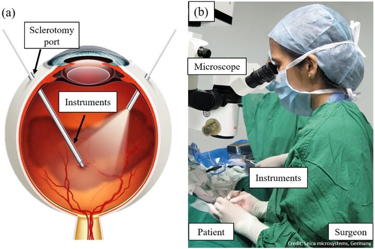
High-precision manipulation is essential for retinal surgery due to high level of safety required to handle delicate tissue in a small constrained workspace. Factors such as physiological hand tremor, fatigue, poor kinesthetic feedback, patient movement, and the absence of force sensing could potentially lead to surgeon’s misoperations, and subsequently iatrogenic injury. During retinal surgery the surgeon inserts small instruments (e.g. 25Ga, ϕ = 0.5mm) through the sclerotomy port (ϕ < 1mm) to perform delicate tissue manipulations in the posterior of the eye as shown in Fig.1. The sclerotomy port continuously sustains variable tool-to-sclera forces. Extreme tool maneuvers applied to the port could result in excessive forces and cause scleral injury. One example of such a challenging retinal surgery task is retinal vein cannulation, a potential treatment for retinal vein occlusion. During this operation, the surgeon needs to pass and hold the needle or micro-pipette through the sclerotomy port and carefully insert it into the occluded retinal vein. After insertion, the surgeon needs to hold the tool steadily for as long as two minutes for clot-dissolving drug injection. In such a delicate operation, any unintentional movements of the surgeon’s hands may put the eye at high risk of injury. Therefore, the success of retinal surgeries is highly dependent on the surgeon’s level of experience and skills, a requirement that could be relaxed with the help of more advanced robotic assistive technology.
Fig. 1.
Illustration of retinal microsurgery. (a): Two tools are inserted into eyeball via sclerotomy port, the sclera sustains constant manipulation force. (b): The surgeon manipulates the instruments under the microscope to perform retinal surgery.
Continuing efforts are being devoted to the development of the surgical robotic systems to enhance and expand surgeon’s capabilities in retinal surgery. Current technology can be categorized into teleoperative manipulation systems [1–3], hand-held robotic devices [4], untethered micro-robots [5], and flexible micro-manipulators [6]. Recently two robot-assisted retinal surgeries have been performed successfully on human patients [7, 8], demonstrating the clinical feasibility of robotic microsurgery.
Our team developed the “steady hand” eye robot (SHER) capable of human-robot cooperative control [9]. Surgical tools can be mounted on the robot end-effector and user manipulates the tool in a collaborative way with the robot. The velocities of SHER follow the user’s manipulation force applied on the tool handle measured by an embedded end-effector force/torque sensor. Furthermore, our group has designed and developed a series of ‘smart” tools based on Fiber Bragg Gratings (FBGs) sensors [10, 11], in which the multi-function sensing tool [12] can measure scleral force, tool insertion depth, and tool tip contact force. Scleral force and insertion depth are the key measurements employed in this work. The measured force is used for force control, and haptic or audio feedback to the surgeon to enhance safety [13, 14].
The aforementioned robotic devices can give passive support to surgeons, i.e. filtering hand tremor, improving tool location accuracy, and providing operation force information to surgeons. However, the existing robotic systems can not actively counteract or prevent iatrogenic accidents (e.g., from extreme scleral forces) caused by surgeon’s misoperations or fatigue, since it is generally difficult to quantify and react on time to the surgeon’s next move.
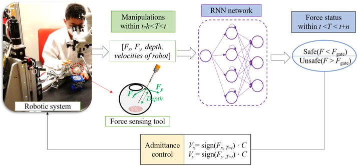
Predicting the surgeon’s following movement based on their prior motions can potentially resolve the above mentioned problems. The predicted information can be used to identify unsafe manipulations that might occur in the near future. Then robotic system could actively take actions e.g., retreating the instruments or pausing the surgeon’s operation to prevent high forces applied to delicate tissue. To this end, we propose an active interventional robotic system (AIRS) summarized in Fig. 2. For an initial study we focus on scleral safety. A force sensing tool is developed to collect scleral force. A recurrent neural network (RNN) with long short term memory (LSTM) units is designed to predict and classify the impending scleral forces into safe and unsafe, using the notion of a safety boundary. An initial linear admittance control taking the predicted force status as input is applied to actuate the robot manipulator to reduce future forces. Finally, AIRS is implemented using SHER research platform and is evaluated by performing “vessel following”, a typical task in retinal surgery, on an eye phantom. The experimental results prove the advantage of AIRS in robot-assisted eye surgery, i.e., the unsafe force proportion is kept below 3% with AIRS compared to 28.3% with SHER and 26.6% with freehand for all participated users.
Fig. 2.
Active interventional robotic system (AIRS). The robotic manipulator is activated to move along the direction of scleral force at a certain velocity once the predicted force status is unsafe. The RNN is trained offline in advance as the predictor. A force sensing tool is developed to measure scleral force (Fx and Fy) and insertion depth.
2. Background
2.1. Fiber Bragg Gratings sensors
FBGs [15] are a type of fiber optic strain sensors. The Bragg gratings work as a wavelength-specific reflector or filter. A narrow spectral component at this particular wavelength, termed the Bragg wavelength, is reflected, while the spectrum without this component is transmitted. The Bragg wavelength is determined by the grating period, which depends on the strain generated in the fiber:
where λB denotes the Bragg wavelength, ne is the effective refractive index of the grating, and Λ denotes the grating period.
We use FBGs as force sensor, since they are small enough (60–200 μm in diameter) to be integrated into the tool without significantly increasing the tool’s dimensions. Besides, FBG sensors are very sensitive, and they can detect strain changes of less than 1 με. They are lightweight, biocompatible, sterilizable, multiplexable, and immune to electrostatic and electromagnetic noise.
2.2. Force Sensing Tool
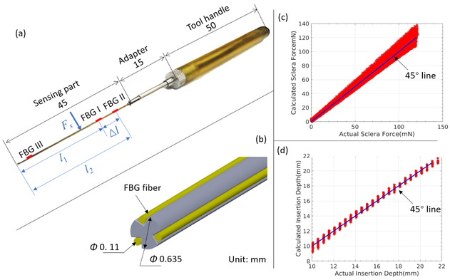
The force sensing tool was previously designed and fabricated as shown in Fig. 3, which is employed to measure the scleral force and insertion depth in this work. The tool is composed of three parts: tool handle, adapter, and tool shaft (sensing part). The tool shaft is made of a stainless steel wire with the diameter of 0.635 mm. It is machined to contain three longitudinal V-shape grooves. An optical fiber is carefully glued and positioned inside each groove. Each fiber contains three FBG sensors (Technica S.A, Beijing, China) which are separately located in segments I, II, and III. Hence nine FBG sensors are embedded in the tool shaft in total.
Fig. 3.
Force sensing tool. (a): Overall dimension of the tool. The sensing part contains nine FBG sensors, which are located on three segments along tool shaft. (b): The radial positions of FBG fibers on tool shaft. (c): The calibration results of scleral force. The measurement RMS errors of sclera force is 3.8 mN. (d): The calibration results of insertion depth. The measurement RMS errors of insertion depth is 0.3 mm.
The tool is calibrated using previously developed algorithm [12] to measure sclera force and insertion depth. The sclera force can be calculated using Eq. (1) :
| (1) |
where Δl = lII – lI is the constant distance between FBG sensors of segment I and II as shown in Fig. 3. Fs = [Fx, Fy]T is the sclera force applied at sclerotomy port. Mi = [Mx, My]T denotes the moment attributed to Fs on FBG sensors of segment i. Ki (i =I,II) are 3 × 2 constant coefficient matrices, which are obtained through the tool calibration procedures. ΔSi = [Δsi1, Δsi2, Δsi3]T denotes the sensor reading of FBG sensors in segment i, which is defined as below:
| (2) |
where Δλij is the wavelength shift of the FBG, i = I, II is the FBG segment, j = 1, 2, 3 denotes the FBG sensors on the same segment. The insertion depth can be obtained from the magnitude ratio of the moment and the force:
| (3) |
where ∥ · ∥ denotes the vector Euclidean norm. When the magnitude of the sclera force Fs is small, the insertion depth calculated using Eq. (3) can be subject to a large error, so Eq. (3) is only valid when the sclera force Fs is bigger than a preset threshold (e.g., 10 mN).
3. Active Interventional Robotic System
Our proposed system consists of four main parts: the force sensing tool, an RNN, an admittance control algorithm and the SHER research platform as depicted in Fig. 2. The tool held by the user is attached to the robot which can also manipulate it to intervene when needed. The scleral force and the insertion depth are measured by the force-sensing tool in real time. These parameters along with the robot Cartesian velocities are recorded and fed into the RNN as input. The network predicts the scleral force a few hundreds milliseconds away from the current moment. The predicted results are used to implement the admittance control. If the predicted forces are about to exceed the safe boundaries, the admittance control is activated and the robot makes an autonomous motion to reduce the forces.
3.1. RNN network Design
RNNs are suitable for modeling time-dependent tasks such as a surgical procedure. Classical RNNs typically suffer from the gradient vanishing problem when trained with back propagation through time, due to its deep connections over long time periods. To overcome this problem the LSTM model [16] was proposed, which can capture long range dependencies and nonlinear dynamics and model varying-length sequential data, achieving good results for problems spanning clinical diagnosis [17], image segmentation [18], and language modeling [19].
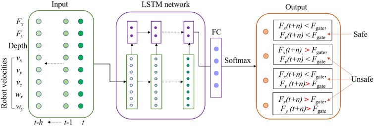
We assume that the scleral force characteristics can be captured through a short time history of sensor measurements (e.g. the last few seconds). An LSTM network [16] is constructed to make predictions based on such history as shown in Fig. 4. The network is based on memory cells composed of four main elements: one input gate, one forget gate, one output gate, and one neuron with a self-recurrent connection (a connection to itself). The gates serve to modulate the interactions between the memory cell itself and its environment. The input gate determines whether the current input should feed into the memory, the output gate manages whether the current memory state should proceed to the next unit, and the forget gate decides whether the memory should be cleared. The following standard equations describe recurrent algebraic relationship of the LSTM unit:
| (4) |
| (5) |
| (6) |
| (7) |
| (8) |
| (9) |
where ht–1 stands for the memory cells at the previous sequence step, σ stands for an element-wise application of the sigmoid (logistic) function, φ stands for an element-wise application of the tanh function, and ⊙ is the Hadamard (element-wise) product. The input, output, and forget gates are denoted by i, o, and f respectively, while C is the cell state. Wf, Wi, WC, and Wo are the weight for forget gate, input gate, cell state, and output state, respectively. bf, bi, bC and bo are the bias for forget gate, input gate, cell state, and output state, respectively. In this work, the LSTM unit uses memory cells with forget gates but without peephole connections.
Fig. 4.
The proposed RNN. The network gets input from data history with h timesteps in past, and outputs the probabilities of each force status at time t+n, where t is the current timestep. Then the one with the highest probability is selected as the final force status, which is further fed into the admittance control.
To perform sensor reading predictions, a fully connected (FC) layer with softmax activation function as shown in Eq. 10 is used as the network output layer after the LSTM units, which outputs the normalized probabilities for each label.
| (10) |
where xi is the output of FC layer, yi is the normalized probability, and n is the number of classes, i.e., force status.
The proposed RNN network takes the scleral force, the insertion depth, and the robot manipulator’s Cartesian velocities in past h timesteps as the input, and outputs the probabilities of the future scleral force statuses i.e., safe/unsafe t+n timesteps in the future, where t denotes the current time, n is the prediction time in future. Then the one with the highest probability is selected as the final force status and is further fed into the admittance control. The groundtruth labels are generated based on the forces within a prediction time window (t, t + n), as shown in Eq. (11):
| (11) |
where Fgate is safety threshold of scleral force, which is set as 60 mN referred to our previous work [20]. Labels that are assigned as 0 represents safe status, otherwise unsafe status. Fx(t)* and Fy(t)* are the maximum scleral forces within the prediction time window shown as following:
| (12) |
| (13) |
where ∣ · ∣ denotes the absolute value.
3.2. Admittance Control Method
An admittance robot control scheme is proposed using the approach described in [21] as a starting point. During cooperative manipulation, the user’s manipulation force which is applied on the robot handle is measured and fed as an input into the admittance control law as shown in Eq. (14):
| (14) |
| (15) |
where and are the desired robot handle velocities in the handle frame and in the robot frame, respectively. Fhh is the user’s manipulation force measured in the handle frame, α is the admittance gain tuned by the robot pedal, Adgrh is the adjoint transformation as shown below, it is associated with the coordinate frame transformation grh.
| (16) |
where Rrh and prh are rotation and translation component of the frame transformation grh, is the skew symmetric matrix that is associated with the vector prh.
The linear admittance control scheme is activated when the predicted scleral forces turns to the unsafe status. The desired robot handle velocities in Eq. 14 change as following:
| (17) |
where W is diagonal admittance matrices can be set as diag([0, 0, 1, 1, 1, 1]T), V is compensational velocity to reduce scleral force, it can be written as following:
| (18) |
where c is set as a constant value.
The robot motion mode is switched back to the original control mode as shown in Eq. (14) when the predicted forces returns to the safe status.
4. EXPERIMENTS AND RESULTS
4.1. Experimental Setup
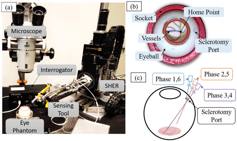
The experimental setup is shown as Fig. 5 (a) and includes SHER, the force sensing tool, and an eye phantom. Besides, an FBG interrogator (SI 115, Micron Optics Inc., GA, USA) is utilized to monitor signals of FBG sensors within the spectrum from 1525 nm to 1565 nm at 2 kHz refresh rate. A microscope (ZEISS, Germany) and a monitor are used to provide magnified view. A Point Grey camera (FLIR Systems Inc., BC, Canada) is attached to the microscope for recording the user’s interaction with the eye. A shared memory architecture is implemented to integrate the RNN predictor running in python into the robotic control system running in C++. We focus on vessel following as a representative surgical task.
Fig. 5.
Experimental setup. (a): the sensing tool is mounted on the SHER end-effector, and the eye phantom is attached on a stage. (b): the eyeball is made of sillicon rubber and is fixed into a socket. (c): The vessel following task consists six phases including approaching sclerotomy port, insertion, forward trace the curve, backward trace the curve, retraction and move away from the eyeball.
4.1.1. Force sensing tool calibration
The force sensing tool is mounted on SHER and used to collect the scleral force and the insertion depth. It is calibrated based on Eq. (1) using a precision scale (Sartorius ED224S Extend Analytical Balance, Goettingen, Germany) with resolution of 1 mg. The details of the calibration procedure were presented in our previous work [12]. The calibration matrices used in Eq. (1) are obtained as below:
The tool validation experiment is carried out with the same scale to test the calibration results. The validation results of the calculated force and the groundtruth values are shown in Fig. 3 (b) and (c). The measurement Root Mean Square (RMS) errors of the sclera force and the insertion depth are calculated to be 3.8 mN and 0.3 mm, respectively.
4.1.2. Eye phantom
An eye phantom is developed using silicon rubber and is placed into a 3D-printed socket as shown in Fig. 5 (b). A printed paper with four curved lines representing the retinal vessels is glued on the eyeball inner surface. The curved lines are painted with different colors, and all lines intersect at the central point called “home” position.
4.1.3. Vessel following operation
Based on the recommendation of our clinical lead, “vessel following” which is a typical task in retinal surgery was chosen for the validation experiments. Vessel following can be performed using the eye phantom and is mainly comprised of 6 phases as shown in Fig 5 (c): (1) moving the tool to approach sclerotomy port, (2) inserting the tool into the eyeball through sclerotomy port to reach the home point, (3) following one of the colored curved vessels with the tool tip without touching the vessel, (4) tracing the curve backward to the home point, (5) retracting the tool to the sclerotomy port, (6) move the tool away from the eyeball.
4.1.4. Shared memory
The RNN network runs in python at 100 Hz, while the robotic system runs in C++ at 200 Hz. To integrate the RNN network into the robotic systems, a shared memory architecture is used as the bridge to transmit the actual user operation data and network prediction results between two programs as shown in Fig. 6. Considering the elapsed time per single prediction Δt, the time of predicted results reaching robotic systems turns out to be T = t + n – Δ t, where n is the prediction time.
Fig. 6.
Data flow of the systems. Real time prediction is n-Δt time ahead, where n is the RNN prediction time, Δt is the elapsed time in one prediction.
4.2. Network Training
The above-mentioned vessel following operation is performed 50 times by a SHER-familiar engineer, the collected data is used to train the RNN. The groundtruth labels are generated using Eq. (11). Successful training critically depends on the proper choice of network hyperparameters [22]. To find a suitable set of the hyper-parameters, i.e., network size and depth, and learning rate, we apply cross validation and random search. The learning rate is chosen as a constant number 2e-5, and the LSTM layer is set as 100 neurons. We use the Adam optimization method [23] as the optimizer and the categorical cross entropy as the loss function. Note that for training the network, we cannot shuffle the sequences of the dataset because the network is learning the sequential relations between the inputs and the outputs. In our experience, adding dropout does not help with the network performance. The training dataset is divided into mini-batches of sequences of size 500. We normalized the dataset value into the range of 0 to 1. The network is implemented with Keras [24], a high-level neural networks API. Training is performed on a computer equipped with Nvidia Titan Black GPUs, a 20-cores CPU, and 128GB RAM. Single-GPU training takes 90 minutes.
The performances of different RNN networks are shown as Table 1, where accuracy is the true positive of prediction result, and successful rate is the prediction result excluding the false negative. Stacked LSTM model with the absolute value of the input data has the highest accuracy which is 89% but its single prediction takes longer time which is 25 ms than LSTM model, the latter takes 11 ms. We finally apply LSTM model in our experiments to get the best trade off between prediction accuracy and timeliness. The chosen LSTM model obtains 89% prediction successful rate.
Table 1.
PERFORMANCE OF THE RNN NETWORKS
| Model | Input data | Prediction time n |
Accuracy | Successful rate |
Elapsed time/ one prediction t |
|---|---|---|---|---|---|
| Stacked LSTM | Vanilla value | 100 ms | 83% | 85% | 26 ms |
| Stacked LSTM | Derivative value | 100 ms | 68% | 75% | 26 ms |
| Stacked LSTM | Absolute derivative value | 100 ms | 76% | 78% | 26 ms |
| Stacked LSTM | Absolute value | 100 ms | 89% | 92% | 26 ms |
| LSTM | Absolute value | 100 ms | 87% | 91% | 10ms |
| LSTM | Absolute value | 200 ms | 85% | 89% | 10ms |
4.3. Active Interventional Robotic System Evaluation
The feasibility of AIRS is evaluated in real time by performing the vessel following operations. The research study was approved by the Johns Hopkins Institutional Review Board. Three non-clinician users took part in the study. With the assistance of AIRS, users are asked to hold the force sensing tool which is mounted on SHER to carry out vessel following task on the eye phantom. The operation is repeated 10 times by each user. Meantime, the benchmark experiments are also performed in freehand operation and in SHER assisted operation respectively.
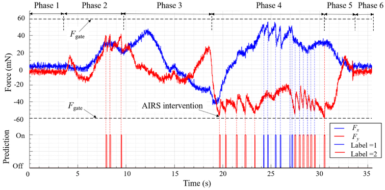
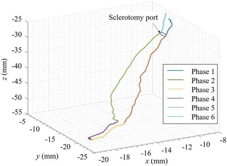
With the assistance of AIRS, the force landscape in one typical vessel following operation is depicted as shown in Fig. 7. The tool tip trajectory in the robot coordinate frame during this operation is shown accordingly in Fig. 8. When the label turns to be on, the scleral force in the next 200 ms will possibly run over the safety threshold Fgate. At this moment AIRS takes action to suppress the scleral force to prevent the unsafe forces from happening. The evaluation results of AIRS as well as two benchmark group are shown in Table 2. Four metrics are calculated including the maximum scleral forces, the unsafe force (force’s absolute value is larger than the safety threshold) duration, the total duration of the experiments, and the unsafe forces proportion which is the ratio of the unsafe force duration and the total duration. It should be mentioned that the metrics are obtained from the conjunct data of ten trails for each user in each conditions. The results show that the maximum forces, the unsafe force duration and the unsafe forces proportion with AIRS are less than the ones with SHER for all three users, and less than the ones with freehand for user 1 and user 2. The total duration with AIRS and with SHER are similar, but both of them are larger than the one with freehand.
Fig. 7.
Forces landscape with predictions. When “Label = 1” is on, Fx in the imminent 200 ms would possibly go over the safety threshold Fgate. Same situation suits for “Label=2” and Fy. The linear admittance control is activated to actuate the robot manipulator to reduce scleral force when label emerges.
Fig. 8.
Typical tool trajectory in vessel following operation. The six phases of the tool tip motion, i.e., approaching the eyeball, insertion, forward tracing the curve, backward tracing the curve, retraction and move away from the eyeball are drew in different colors.
Table 2.
EVALUATION RESULTS
| User | Metrics | Experimental conditions | ||
|---|---|---|---|---|
| Freehand | With SHER | with AIRS | ||
| 1 | Maximum (Fx, Fy) (mN) | (124.5,114.6) | (113.1,113.8) | (78.7, 52.4) |
| Unsafe force duration (s) | 32.6 | 56.1 | 9.5 | |
| Total duration (s) | 165.7 | 313.1 | 318.7 | |
| Unsafe forces proportion | 19.6% | 17.8% | 3.0% | |
| 2 | Maximum (Fx, Fy) (mN) | (124.8,147.4) | (75.5,116.8) | (74.5, 68.6) |
| Unsafe force duration (s) | 38.1 | 100.9 | 3.2 | |
| Total duration (s) | 143.0 | 356.5 | 370 | |
| Unsafe forces proportion | 26.6% | 28.3% | 0.84% | |
| 3 | Maximum (Fx, Fy) (mN) | (61.4,58.6) | (96.6,151.4) | (65.2, 83.5) |
| Unsafe force duration (s) | 2.5 | 106.1 | 9.9 | |
| Total duration (s) | 309.2 | 434.4 | 397.6 | |
| Unsafe forces proportion | 0.8% | 24.4% | 2.49% | |
5. DISCUSSION
Robotic assistance could help eliminating hand tremor and improve precision [7,8]. However, it could affect surgeon’s tactile perception and in turn cause larger manipulation forces compared to freehand due to mechanical coupling and stiffness. Moreover, robotic assistant could prolong surgery time compared to freehand maneuver because a robotic assistant could restrict the surgeon’s hand dexterity. This is evident from our empirical results, where the fraction of unsafe forces with SHER are similar (for user 1) or even larger (for user 2 and user 3) than the ones with freehand, and the total procedure durations are longer with SHER than that with freehand for all users, as shown in Table 2. These results are consistent with our previous study [25]. These phenomena could potentially weaken the advantage of robotic assistance in retinal surgery and lower the enthusiasm to robotic technology for users who possess unique ability and skills to maintain steady motions with their hands (e.g, user 3).
However, the addition of our proposed AIRS system could remedy the limitation of the existing robotic assistant by capturing the user’s operation and eliminate potentially imminent extreme scleral forces before they occur. As shown in Table 2, the maximum forces and the unsafe force proportion with AIRS decrease sharply compared to the ones with robot, and are comparable (for user 3) or less than (for user 1 and user 2) the value with freehand. These results demonstrate that AIRS could enhance safety of manipulation using robotic assistance.
We chose the LSTM model as the predictor in AIRS which obtained 89% prediction successful rate. Although the predictor has 11% failure rate to capture the unsafe scleral force in advance, which might lead AIRS to omit a small portion of unsafe cases, AIRS significantly enhances the existing SHER by keeping keep scleral force in a safe range as shown in Table 2. Currently only the manipulation data from a SHER familiar engineer is used to train the network, which may lead to improper output for a surgeon’s operation. Therefore a remaining limitation is that our system requires larger datasets from multiple users including surgeons and further development of the learning models in order to provide trustworthy confidence intervals during inference. This will be the focus of future work.
6. CONCLUSION
We implemented AIRS by developing a force sensing tool to collect scleral forces and the insertion depth, used along with robot kinematics as inputs to an RNN network to learn a model of user behavior and predict the imminent scleral force unsafe mode, which are then used by an admittance control method to enable the robot to take action to prevent the sclera injury. The feasibility of AIRS is evaluated with multiple users in a vessel following task. The results show that AIRS could potentially provide safe manipulation that can improve the outcome of the retinal microsurgery. The presented method could also be applied in other types of microsurgery.
This work was only considered sclera forces. Future work will incorporate the predicted insertion depth together with the predicted scleral force to implement multiple variable admittance control, to enable more versatile modeling of potential tissue damage. It is also critical to involve a larger set of users and different surgical tasks. Our force sensing tool can also measure the force at the tool tip, which will also be incorporated into the network training in future work to provide more information for robot control. Finally, while in this initial study we applied a linear non-smooth admittance control in AIRS as the first step to evaluate the system feasibility, non-linear admittance control method will be explored in the future to achieve smooth robot motion.
Acknowledgments
*This work was supported by U.S. National Institutes of Health under grant 1R01EB023943-01. The work of C. He was supported in part by the China Scholarship Council under grant 201706020074, National Natural Science Foundation of China under grant 51875011, and National Hi-tech Research and Development Program of China with grant 2017YFB1302702.
Footnotes
Conflict of interest The authors declare that they have no conflict of interest.
Ethical approval All procedures performed in studies involving human participants were in accordance with the protocol approved by the Johns Hopkins Institutional Review Board.
Informed consent Informed consent was obtained from all individual participants included in the study.
Contributor Information
Changyan He, School of Mechanical Engineering and Automation at Beihang University, Beijing, 100191 China, and LCSR at the Johns Hopkins University, Baltimore, MD 21218 USA, Tel.: +1 4435293749, changyanhe@jhu.edu.
Niravkumar Patel, LCSR at the Johns Hopkins University, Baltimore, MD 21218 USA, npatel89@jhu.edu.
Ali Ebrahimi, LCSR at the Johns Hopkins University, Baltimore, MD 21218 USA, aebrahi5@jhu.edu.
Marin Kobilarov, LCSR at the Johns Hopkins University, Baltimore, MD 21218 USA, marin@jhu.edu.
Iulian Iordachita, LCSR at the Johns Hopkins University, Baltimore, MD 21218 USA, iordachita@jhu.edu.
References
- 1.Rahimy E, Wilson J, Tsao T, Schwartz S, and Hubschman J, “Robot-assisted intraocular surgery: development of the iriss and feasibility studies in an animal model,” Eye, vol. 27, no. 8, p. 972, 2013. [DOI] [PMC free article] [PubMed] [Google Scholar]
- 2.Ueta T, Yamaguchi Y, Shirakawa Y, Nakano T, Ideta R, Noda Y, Morita A, Mochizuki R, Sugita N, Mitsuishi M, Tamaki Y, “Robot-assisted vitreoretinal surgery: Development of a prototype and feasibility studies in an animal model,” Ophthalmology, vol. 116, no. 8, pp. 1538–1543, 2009. [DOI] [PubMed] [Google Scholar]
- 3.He C, Huang L, Yang Y, Liang Q, and Li Y, “Research and realization of a master-slave robotic system for retinal vascular bypass surgery,” Chinese Journal of Mechanical Engineering, vol. 31, no. 1, p. 78, 2018. [Google Scholar]
- 4.MacLachlan RA, Becker BC, Tabarés JC, Podnar GW, Lobes LA Jr, and Riviere CN, “Micron: an actively stabilized handheld tool for microsurgery,” IEEE Transactions on Robotics, vol. 28, no. 1, pp. 195–212, 2012. [DOI] [PMC free article] [PubMed] [Google Scholar]
- 5.Kummer MP, Abbott JJ, Kratochvil BE, Borer R, Sengul A, and Nelson BJ, “Octomag: An electromagnetic system for 5-dof wireless micromanipulation,” IEEE Transactions on Robotics, vol. 26, no. 6, pp. 1006–1017, 2010. [Google Scholar]
- 6.Hubschman J, Bourges J, Choi W, Mozayan A, Tsirbas A, Kim C, and Schwartz S, “the microhand: a new concept of micro-forceps for ocular robotic surgery,” Eye, vol. 24, no. 2, p. 364, 2010. [DOI] [PubMed] [Google Scholar]
- 7.Edwards T, Xue K, Meenink H, Beelen M, Naus G, Simunovic M, Latasiewicz M, Farmery A, de Smet M, and MacLaren R, “First-in-human study of the safety and viability of intraocular robotic surgery,” Nature Biomedical Engineering, p. 1, 2018. [DOI] [PMC free article] [PubMed] [Google Scholar]
- 8.Gijbels A, Smits J, Schoevaerdts L, Willekens K, Vander Poorten EB, Stalmans P, and Reynaerts D, “In-human robot-assisted retinal vein cannulation, a world first,” Annals of Biomedical Engineering, pp. 1–10, 2018. [DOI] [PubMed] [Google Scholar]
- 9.Üneri A, Balicki MA, Handa J, Gehlbach P, Taylor RH, and Iordachita I, “New steady-hand eye robot with micro-force sensing for vitreoretinal surgery,” in Biomedical Robotics and Biomechatronics (BioRob), 2010 3rd IEEE RAS and EMBS International Conference on IEEE, 2010, pp. 814–819. [DOI] [PMC free article] [PubMed] [Google Scholar]
- 10.Iordachita I, Sun Z, Balicki M, Kang JU, Phee SJ, Handa J, Gehlbach P, and Taylor R, “A sub-millimetric, 0.25 mn resolution fully integrated fiber-optic force-sensing tool for retinal microsurgery,” International journal of computer assisted radiology and surgery, vol. 4, no. 4, pp. 383–390, 2009. [DOI] [PMC free article] [PubMed] [Google Scholar]
- 11.He X, Handa J, Gehlbach P, Taylor R, and Iordachita I, “A submillimetric 3-dof force sensing instrument with integrated fiber bragg grating for retinal microsurgery,” IEEE Transactions on Biomedical Engineering, vol. 61, no. 2, pp. 522–534, 2014. [DOI] [PMC free article] [PubMed] [Google Scholar]
- 12.He X, Balicki M, Gehlbach P, Handa J, Taylor R, and Iordachita I, “A multi-function force sensing instrument for variable admittance robot control in retinal microsurgery,” in Robotics and Automation (ICRA), 2014 IEEE International Conference on IEEE, 2014, pp. 1411–1418. [DOI] [PMC free article] [PubMed] [Google Scholar]
- 13.Cutler N, Balicki M, Finkelstein M, Wang J, Gehlbach P, McGready J, Iordachita I, Taylor R, and Handa JT, “Auditory force feedback substitution improves surgical precision during simulated ophthalmic surgery,” Investigative ophthalmology & visual science, vol. 54, no. 2, pp. 1316–1324, 2013. [DOI] [PMC free article] [PubMed] [Google Scholar]
- 14.Ebrahimi A, He C, Roizenblatt M, Patel, Niravkumar S, Sefati, Gehlbach P, and Iordachita I, “Real-time sclera force feedback for enabling safe robot assisted vitreoretinal surgery,” in Engineering in Medicine and Biology Society (EMBC), 2018 40th Annual International Conference of the IEEE IEEE, 2018, pp. 3650–3655. [DOI] [PMC free article] [PubMed] [Google Scholar]
- 15.Othonos A, Kalli K, Pureur D, and Mugnier A, “Fibre bragg gratings,” in Wavelength Filters in Fibre Optics. Springer, 2006, pp. 189–269. [Google Scholar]
- 16.Hochreiter S and Schmidhuber J, “Long short-term memory,” Neural computation, vol. 9, no. 8, pp. 1735–1780, 1997. [DOI] [PubMed] [Google Scholar]
- 17.Lipton ZC, Kale DC, Elkan C, and Wetzel R, “Learning to diagnose with lstm recurrent neural networks,” arXivpreprint arXiv:1511.03677, 2015. [Google Scholar]
- 18.Stollenga MF, Byeon W, Liwicki M, and Schmidhuber J, “Parallel multi-dimensional lstm, with application to fast biomedical volumetric image segmentation,” in Advances in neural information processing systems, 2015, pp. 2998–3006. [Google Scholar]
- 19.Sundermeyer M, Schlüter R, and Ney H, “Lstm neural networks for language modeling,” in Thirteenth Annual Conference of the International Speech Communication Association, 2012. [Google Scholar]
- 20.Horise Y, He X, Gehlbach P, Taylor R, and Iordachita I, “Fbg-based sensorized light pipe for robotic intraocular illumination facilitates bimanual retinal microsurgery,” in Engineering in Medicine and Biology Society (EMBC), 2015 37th Annual International Conference of the IEEE IEEE, 2015, pp. 13–16. [DOI] [PubMed] [Google Scholar]
- 21.Kumar R, Berkelman P, Gupta P, Barnes A, Jensen PS, Whitcomb LL, and Taylor RH, “Preliminary experiments in cooperative human/robot force control for robot assisted microsurgical manipulation,” in Robotics and Automation, 2000. Proceedings. ICRA’00. IEEE International Conference on, vol. 1 IEEE, 2000, pp. 610–617. [Google Scholar]
- 22.Greff K, Srivastava RK, Koutnik J, Steunebrink BR, and Schmidhuber J, “Lstm: A search space odyssey,” IEEE transactions on neural networks and learning systems, vol. 28, no. 10, pp. 2222–2232, 2017. [DOI] [PubMed] [Google Scholar]
- 23.Kingma DP and Ba J, “Adam: A method for stochastic optimization,” arXiv preprint arXiv:1412.6980, 2014. [Google Scholar]
- 24.Chollet F, “Keras,” https://github.com/keras-team/keras, 2015.
- 25.He C, Ebrahimi A, Roizenblatt M, Patel N, Yang Y, Gehlbach PL, and Iordachita I, “User behavior evaluation in robot-assisted retinal surgery,” in 2018 27th IEEE International Symposium on Robot and Human Interactive Communication (RO-MAN) IEEE, 2018, pp. 174–179. [DOI] [PMC free article] [PubMed] [Google Scholar]


