Abstract
To characterize keratin intermediate filament assembly mechanisms at atomic resolution, we determined the crystal structure of wild‐type human keratin‐1/keratin‐10 helix 1B heterotetramer at 3.0 Å resolution. It revealed biochemical determinants for the A11 mode of axial alignment in keratin filaments. Four regions on a hydrophobic face of the K1/K10‐1B heterodimer dictated tetramer assembly: the N‐terminal hydrophobic pocket (defined by L227K1, Y230K1, F231K1, and F234K1), the K10 hydrophobic stripe, K1 interaction residues, and the C‐terminal anchoring knob (formed by F314K1 and L318K1). Mutation of both knob residues to alanine disrupted keratin 1B tetramer and full‐length filament assembly. Individual knob residue mutant F314AK1, but not L318AK1, abolished 1B tetramer formation. The K1‐1B knob/pocket mechanism is conserved across keratins and many non‐keratin intermediate filaments. To demonstrate how pathogenic mutations cause skin disease by altering filament assembly, we additionally determined the 2.39 Å structure of K1/10‐1B containing a S233LK1 mutation linked to epidermolytic palmoplantar keratoderma. Light scattering and circular dichroism measurements demonstrated enhanced aggregation of K1S233L/K10‐1B in solution without affecting secondary structure. The K1S233L/K10‐1B octamer structure revealed S233LK1 causes aberrant hydrophobic interactions between 1B tetramers.
Keywords: intermediate filament, keratin, skin disease, structure, vimentin
Subject Categories: Cell Adhesion, Polarity & Cytoskeleton; Structural Biology
Introduction
One of the most critical questions in keratin biology is how keratin heterodimers assemble into keratin intermediate filaments (KIFs). Multiple biophysical studies have defined the stages of IF assembly as: One type I keratin and one type II keratin pair to form a parallel heterodimer; heterodimers then bind to form an anti‐parallel tetramer; tetramers then merge to form a protofibril/unit‐length filament; and finally, protofibrils assemble into the complete KIF (Aebi et al, 1983; Parry et al, 2001; Herrmann & Aebi, 2016). A major knowledge gap exists in understanding the biochemical determinants of KIF assembly at atomic resolution. Recent X‐ray crystal structures of the keratin 1/10 and keratin 5/14 helix 2B heterodimers provided key insights into heterodimer structure, such as the electrostatic and hydrophobic chemistry of the molecular surface (Lee et al, 2012; Bunick & Milstone, 2017). These structures did not, aside from a disulfide linkage related to inter‐filament organization, capture information on how heterodimers assemble into KIFs.
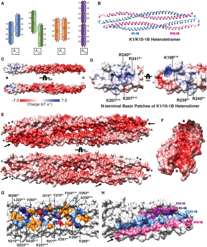
Four modes of axial alignment of keratin heterodimers within a filament have been proposed based on keratin 1/10 and 5/14 cross‐linking studies (Steinert et al, 1993a; Steinert et al, 1993b; Fig 1A). Two modes contain heterodimers in an anti‐parallel, staggered alignment such that either the 1B coiled‐coil segments are in phase (A11 mode) or the 2B coiled‐coil segments are in phase (A22 mode). One mode contains two anti‐parallel heterodimers in almost exact register (A12 mode), but without any specific coiled‐coil region being in phase with itself. The fourth mode is a head‐to‐tail alignment of the helical rod domain (i.e., helices 1A, 1B, 2A, 2B) with ~ 10 residues overlapping between the 1A helix from one heterodimer and the 2B helix from another (ACN mode). To date, there have been no crystal structures of human keratins that elucidate the molecular mechanisms of any of these axial alignments. For other types of IF proteins, however, crystal structures of vimentin (type III IF) and lamin A (type V IF) domains have provided molecular insights into the A11 and ACN modes of tetramer assembly, respectively (Strelkov et al, 2004; Aziz et al, 2012; Chernyatina et al, 2012, 2015). In the case of lamin A, it was proposed that head‐to‐tail association occurs because clusters of positively charged arginine residues in the head and tail domains interact with negatively charged residues in the ends of the helical rod domain (Strelkov et al, 2004). The arginine clusters, however, are not conserved among keratin heads and tails. This difference highlights why it is necessary to study further the structural mechanisms governing higher order IF assemblies, especially for keratins.
Figure 1. Molecular surface properties of the wild‐type K1/K10‐1B dimer and tetramer.
-
AThe four proposed modes of keratin tetramer alignment in filament formation.
-
BRibbon diagram of the wild‐type K1/K10‐1B tetramer crystal structure at 3.0 Å resolution. Helices within one heterodimer (the crystal asymmetric unit) are oriented parallel, whereas the two heterodimers in the tetramer are anti‐parallel.
-
CElectrostatic surface potential mapped onto the K1/K10‐1B heterodimer structure demonstrates a polarization of charge: The N‐terminus has some basic charge (blue), while the majority of the distal 1B dimer is acidic (red).
-
DClose‐up view of the N‐terminal basic patches on the K1/K10‐1B heterodimer. Three K1 (R239, R240, and R241) and three K10 (K198, K201, and K207) residues contribute positive charge. One basic patch (left) surrounds a hydrophobic pocket involved in tetramer formation (asterisk).
-
E, FElectrostatic surface potential mapped onto the K1/K10‐1B tetramer structure demonstrates it is overwhelmingly acidic: The anti‐parallel orientation of the dimers within the tetramer eliminates the small basic potential at the dimer N‐terminus. Unique molecular surface contours are present in the K1/K10‐1B tetramer that do not exist in the dimer: One tetramer face has a long, linear, highly acidic surface groove (top of panel E, arrows; panel F, asterisks), whereas the other face contains a central concave pocket (bottom of panel E, asterisk) flanked by angled grooves (bottom of panel E, arrows).
-
GResidues forming the central concave pocket on one face of the K1/K10‐1B tetramer are shown and colored based on residue property (red, acidic; dark blue, basic; orange, hydrophobic; light blue, polar). The asterisk marks the twofold symmetry axis in the tetramer.
-
HClose‐up view of one “angled groove” (arrow) in the K1/K10‐1B tetramer colored to demonstrate a portion of all four tetramer helices contributes to groove formation. Some of the anchoring knob/hydrophobic pocket residues are accessible in the groove (yellow asterisk).
After we determined the keratin 1/10‐2B heterodimer structure (Bunick & Milstone, 2017), the next logical coiled‐coil domain to target for structural studies was the 1B region—the second longest helical domain in keratins (~ 106 amino acids). While the 1A and 2B helices are the most commonly mutated domains in keratinopathies (human skin diseases caused by keratin mutation), the 1B domain also harbors pathogenic mutations. For example, a Ser233Leu missense mutation in K1‐1B causes epidermolytic palmoplantar keratoderma (EPPK). Histologic and electron microscopic examination of skin from patients with EPPK due to S233LK1 mutation revealed KIFs that formed tubular assemblies with enlarged 43 nm diameters rather than normal 10‐nm‐diameter KIFs (Wevers et al, 1991; Terron‐Kwiatkowski et al, 2006). This tubular morphology was described as “tonotubular” keratin as opposed to the “tonofilamentous” keratin observed in healthy skin.
Our goal was to characterize the biochemical and structural properties of the wild‐type keratin 1/10 helix 1B heterodimer and the impact of S233LK1 mutation on that structure. However, efforts to determine the structure of wild‐type keratin 1/10‐1B serendipitously led to the structure of the keratin 1/10‐1B tetramer, a far more valuable structure given the need for atomic resolution information on higher order keratin filament assembly.
The work reported here advances intermediate filament biology in several ways: It provides an atomic resolution basis for the A11 mode of axial alignment in keratin filaments; it identifies an anchoring knob/hydrophobic pocket mechanism that drives helix 1B tetramer assembly not just for keratins, but for other non‐keratin intermediate filaments as well; and it establishes insight into the pathogenic mechanisms of tonotubular keratin formation associated with EPPK. First, we determined a 3.0 Å resolution crystal structure of the wild‐type keratin 1/10‐1B tetramer. Second, multi‐angle light scattering and circular dichroism measurements demonstrated the S233LK1 mutation alters the aggregation state of keratin 1/10‐1B in solution but not the secondary structure. Third, we determined a 2.39 Å resolution crystal structure of K1/10‐1B containing the pathogenic S233LK1 mutation. Fourth, we identified and validated through mutagenesis an “anchoring knob/hydrophobic pocket mechanism” for tetramer assembly. This research addresses knowledge gaps in keratin filament assembly and how pathogenic mutations can lead to human skin disease by altering that assembly.
Results
Wild‐type K1/K10‐1B structure
Using the divide‐and‐conquer approach (Strelkov et al, 2001), the X‐ray crystal structure of the human K1/K10 helix 1B heterotetrameric complex was determined at 3.0 Å resolution (Fig 1B and Table 1; Eldirany et al, 2018). The tetramer is composed of two K1/K10‐1B heterodimers arranged anti‐parallel (one heterodimer is the crystal asymmetric unit). The K1 and K10 molecules within the heterodimer structure form a parallel coiled‐coil, spanning K1 residues (226–331) and K10 residues (195–296). Key molecular interactions along the K1/K10‐1B heterodimer interface are detailed (Fig EV1A and B). The K1/K10‐1B tetramer did not exhibit supercoiling of the coiled‐coil heterodimers. Throughout this manuscript, we will denote protein–protein interactions occurring between the two anti‐parallel dimers of the tetramer by associating a prime symbol with the residue(s) from the second dimer (e.g., K1‐K1′).
Table 1.
Data collection and refinement statistics
| Crystal | Wild‐type K1/K10‐1B | K1S233L/K10‐1B |
|---|---|---|
| Diffraction dataa | ||
| Space group | P 31 2 1 | P 64 2 2 |
| Unit cell dimensions | ||
| a, b, c (Å) | 106.68, 106.68, 70.32 | 93.30, 93.30, 124.74 |
| α, β, γ (°) | 90, 90, 120 | 90, 90, 120 |
| Resolution range (outer shell), Å | 46.20–2.98 (3.05–2.98)b | 46.65–2.39 (2.43–2.39) |
| I/σI | 11.72 (0.64) | 20.2 (1.92) |
| Resolution (Å) where I/σI ~ 1.9 | 3.46 | 2.39 |
| CC(1/2) in outer shell, % | 64.0 | 78.7 |
| Completeness, % | 89.5 (69.9) | 99.9 (99.5) |
| R merge | 0.132 (1.185) | 0.139 (0.969) |
| No. of crystals used | 1 | 1 |
| No. of unique reflections | 8,414 | 13,342 |
| Redundancy | 8.0 (5.0) | 13.3 (10.0) |
| Wilson B‐factor, Å2 | 86.2 | 67.3 |
| Refinement | ||
| R work, % | 0.279 (0.417) | 0.271 (0.349) |
| R free, % | 0.298 (0.478) | 0.294 (0.371) |
| No. of non‐hydrogen atoms | ||
| Protein | 1,731 | 1,751 |
| Ligands/Ions | 9 | 4 |
| Waters | 35 | 60 |
| R.m.s. deviations | ||
| Bond lengths (Å) | 0.006 | 0.004 |
| Angles (°) | 0.876 | 0.587 |
| Chirality | 0.036 | 0.029 |
| Planarity | 0.004 | 0.005 |
| Dihedral (°) | 18.415 | 17.408 |
| Average B‐factor (overall), Å2 | 146.0 | 106.3 |
Data collection was performed on 07‐06‐2017.
Values in parentheses are for highest resolution (outer) shell.
Figure EV1. Structure analysis of wild‐type K1/K10‐1B and mutant K1S233L/K10‐1B heterodimer structures.
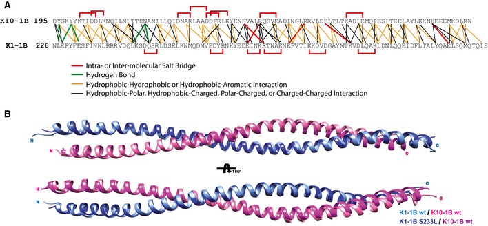
- The amino acid contacts at the heterodimer interface for both wild‐type K1/K10‐1B and mutant K1S233L/K10‐1B X‐ray crystal structures were analyzed and plotted onto a single residue contact map. Intramolecular (within K1 or K10 only) and inter‐molecular (between K1 and K10) salt bridges are plotted red. Hydrogen bonds are plotted green. Interactions between hydrophobic residues are plotted orange (hydrophobic residues are defined as A, I, L, F, V, P, M, W), including hydrophobic interaction with the aromatic residue tyrosine. Other types of molecular contacts are plotted black. Analyses were performed using WHAT IF (defines atoms as “in contact” when the distance between their van der Waals surfaces is < 1.0 Å), ESBRI, and PDBePISA. Since S233K1 is a surface‐exposed residue, its mutation to L233 does not impact the heterodimer interface. Hence, the analysis of both heterodimer interfaces was used to obtain the contact map.
- The wild‐type K1/K10‐1B and mutant K1S233L/K10‐1B heterodimer structures were superimposed and have a root‐mean‐square deviation (RMSD) of 0.736 Å. The superposition shows slight variation in the positioning of the K10 C‐terminus.
The electrostatic surface potential of the K1/K10‐1B heterodimer is similar to that observed in the K1/K10‐2B heterodimer (Bunick & Milstone, 2017): There is polarization of charge with the distal three‐fourths of the complex being acidic, whereas the proximal one‐fourth is more basic (Fig 1C). The basic patch at the N‐terminus of K1/K10‐1B contains residues from both K1 (R239, R240, R241) and K10 (K198, K201, K207; Fig 1D); this is in contrast to the 2B heterodimer, where a linear N‐terminal basic patch was solely formed by nine K1 residues (Bunick & Milstone, 2017).
Acidic groove on molecular surface of 1B tetramer
Due to anti‐parallel alignment of K1/K10‐1B heterodimers in the tetramer, the basic electrostatic surface potential at the N‐terminus of the heterodimer is diminished by the strength of the adjacent acidic C‐terminus in the tetramer (Fig 1E). The electrostatic surface potential of the K1/K10‐1B tetramer is mainly acidic.
There are unique surface contours present in the K1/K10‐1B tetramer that are not present in the heterodimer structure (Fig 1E and H). One face of the tetramer contains a linear groove that extends from one end all the way to the other; this groove has the highest acidic electrostatic surface potential in the K1/K10‐1B tetramer structure (Fig 1E and F). In contrast, the tetramer face 180° opposite the acidic linear groove contains a central concave pocket ~ 66.7 Å long by 17.7 Å wide (Fig 1G), flanked by two symmetric angled grooves ~ 54.9 Å long at either end of the molecule (Fig 1H).
Hydrophobic interactions drive 1B tetramer formation
Mapping of hydrophobic surface potential onto the K1/K10‐1B heterodimer structure demonstrates that one heterodimer face contains multiple surface‐exposed hydrophobic residues, whereas the face 180° opposite is largely polar with only a few exposed hydrophobic residues (Fig 2A). The hydrophobic face of the K1/K10‐1B heterodimer contains the molecular determinants of tetramer assembly. They can be divided into four key segments from N‐ to C‐terminus: a K1 hydrophobic pocket, a K10 hydrophobic stripe, K1 interaction residues, and a K1 anchoring knob (Fig 2B).
Figure 2. Biochemical basis for K1/K10‐1B heterotetramer formation.
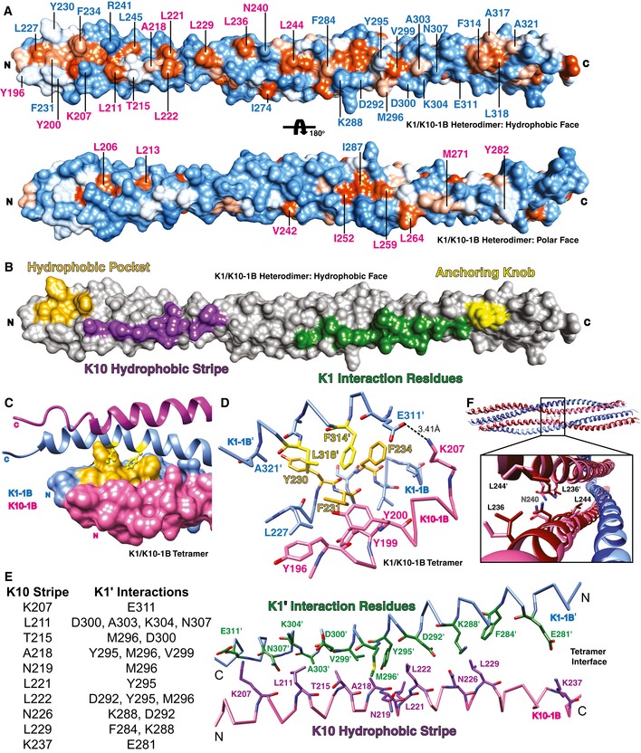
- The molecular surface of the K1/K10‐1B heterodimer can be divided into a predominantly hydrophobic face (top) and a predominantly polar face (bottom). The molecular surface is colored according to hydrophobic potential: Hydrophobic residues are orange, and polar residues are blue (color intensity indicates magnitude of potential). Select residues are labeled blue (K1) or pink (K10).
- Four key regions along the hydrophobic face of the K1/K10‐1B heterodimer drive tetramer formation: an N‐terminal K1 hydrophobic pocket (gold), a K10 hydrophobic stripe (purple), K1 interaction residues (green), and a C‐terminal K1 anchoring knob (yellow). All of the following panels show tetramer interactions.
- One end of the K1/K10‐1B tetramer depicting the anchoring knob residues (yellow sticks) binding into the hydrophobic pocket (gold surface).
- Stick representation of the anchoring knob/hydrophobic pocket mechanism in tetramer formation. F314K1′ and L318K1′ wedge between L227K1, Y230K1, F231K1, and F234K1; the aromatic ring of F314K1′ stacks against that of F234K1. A salt bridge between K207K10 and E311K1′ is shown.
- Ten K10 residues (purple) in the hydrophobic stripe of one dimer (K10 helix backbone pink) interact with 12 K1′ residues (green) from the partner dimer (K1′ backbone light blue) to create an anti‐parallel tetramer interface.
- Close‐up view of the one region in the K1/K10‐1B tetramer where K10 and K10′ interact; this is facilitated by L236K10 interacting with L244K10′. Mutant K1S233L/K10‐1B (K1S233L, dark blue; K10, dark red) is superimposed on wild‐type K1/K10‐1B (K1, light blue; K10, pink). N240K10 is the center of the twofold symmetry in the tetramer; hence, L236‐L244′ and the reciprocal L236′‐L244 interactions are on either side of N240.
At the N‐terminus of the K1/K10‐1B heterodimer, there is a hydrophobic pocket formed by four K1 residues (L227, Y230, F231, and F234). The concavity between the aromatic residues is the receptor site for the C‐terminal anchoring knob on a neighboring K1/K10‐1B heterodimer, facilitating tetramer formation (Fig 2C). The C‐terminal anchoring knob is composed of two K1 residues (F314 and L318). F314K1′ binds by wedging between F231K1 and F234K1, creating a ring‐stacking interaction with F234K1 (Fig 2D). L318K1′ interacts with F231K1 and Y230K1 (~ 3.3 and 4.2 Å, respectively), and knob/pocket docking brings A321K1′ near Y230K1 (~ 3.6 Å) and L318K1′ near L227K1 (~ 4.6 Å).
Adjacent to the hydrophobic pocket, and aligned along the outer aspect of the α‐helical ridge, are several K10 residues constituting a predominantly hydrophobic stripe (Fig 2A and B). A type I keratin “hydrophobic stripe” was identified from modeling analyses of K6/K16/K17 dimers (Bernot et al, 2005); this work showed that most, but not all (e.g., K10), type I keratins contained a consensus hydrophobic sequence at alternating b‐ and f‐ positions of the heptad repeat (L‐x‐x‐x‐(I/V)‐x‐x‐A‐x‐x‐x‐L) contributing to tetramer stability. However, K10 has threonine in the second position of this motif, and in our K1/K10‐1B tetramer structure, the function of this protein region proves complex—there exists an interacting stripe, but the interactions are not strictly hydrophobic. The K10 helical ridge on the N‐terminal half of the K1/K10‐1B heterodimer is defined by 11 K10 residues: K207, L211, T215, A218, N219, L221, L222, N226, L229, K237, and L236. Several of these residues are not hydrophobic (K207, T215, N219, N226, K237) but make meaningful interactions to stabilize tetramer assembly and thus are considered part of the stripe (Fig 2E). K207K10 forms a salt bridge with E311K1′, while T215K10 interacts with M296K1′ and D300K1′ (Fig 2D and E). K10 hydrophobic residues L211, A218, L221, L222, and L229 all have interactions with K1′ residues < 5 Å apart. L236, on the other hand, is involved in K10‐K10′ interactions only (Fig 2F).
The hydrophobic face of the K1/10‐1B heterodimer contains a segment consisting of “K1 interaction residues” between the K10 hydrophobic stripe and the C‐terminal anchoring knob. K1 interaction residues exist on the K1 α‐helix whose helical ridge forms most of the distal hydrophobic face. In the K1/10‐1B tetramer, 12 K1 residues from this segment have hydrophobic or electrostatic interactions with 10 K10 hydrophobic stripe residues from the binding heterodimer (Fig 2E).
S233LK1 mutation drives aggregation of K1/K10‐1B in solution
Keratin 1 containing the missense mutation S233L, which is pathogenic for epidermolytic palmoplantar keratoderma, was produced and purified to investigate how the mutation affects K1/K10‐1B heterodimer structure and function (Fig 3A). After His‐tag removal from K10, wild‐type K1/K10‐1B and mutant K1S233L/K10‐1B complexes were analyzed by gel filtration. Wild‐type K1/K10‐1B separated into two main peaks (Fig 3B, solid line), whereas K1S233L/K10‐1B formed one major peak (Fig 3B, dotted line) that eluted earlier than the wild‐type complex. This suggested K1S233L/K10‐1B formed a higher molecular weight complex in solution than wild‐type K1/K10‐1B.
Figure 3. Biophysical analysis of wild‐type and K1S233L mutant keratin 1/10‐1B in solution.
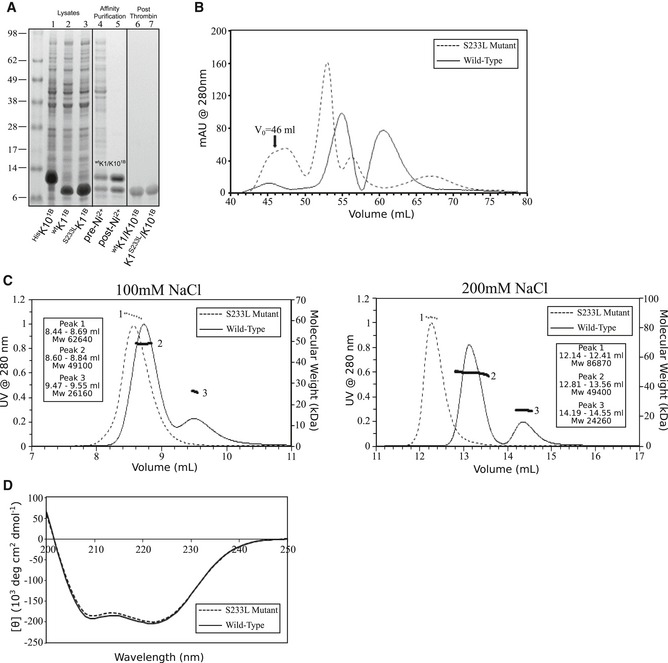
- Bacterial expression lysates for recombinant His6‐tagged K10‐1B (1), wild‐type K1‐1B (2), and K1S233L‐1B (3). Wild‐type K1/K10‐1B before (4) and after (5) nickel affinity purification. Wild‐type K1/10‐1B (6) and K1S233L/K10‐1B (7) after thrombin cleavage of His6‐tag on K10 and subsequent gel filtration (untagged K10 overlaps with K1 after tag removal).
- Gel filtration of wild‐type K1/K10‐1B (solid line) produced two peaks from 52 to 67 ml, whereas the K1S233L/K10‐1B mutant (dotted line) produced one major peak from 50 to 55 ml that eluted earlier than wild type. V 0 = void volume.
- Multi‐angle light scattering demonstrated wild‐type K1/K10‐1B (solid line) exists mostly as a tetramer (observed MW 49,100; calculated tetramer MW 49,700), with a small amount of dimer (observed MW 26,160; calculated MW 24,840), in 100 mM NaCl solution. This does not change in 200 mM NaCl. K1S233L/K10‐1B forms higher MW aggregates than wild type in both 100 mM NaCl (observed MW 62,640) and 200 mM NaCl (observed MW 86,870) solutions.
- Circular dichroism shows identical helical secondary structure for wild‐type K1/K10‐1B and mutant K1S233L/K10‐1B.
To characterize the oligomerization state of these complexes, K1/K10‐1B and K1S233L/K10‐1B were analyzed by multi‐angle light scattering in either 100 mM NaCl or 200 mM NaCl solutions (Fig 3C). Wild‐type K1/K10‐1B (solid line) formed a tetramer species (peak 2, ~ 49 kDa) and a dimer species (peak 3, ~ 24–26 kDa) in both 100 and 200 mM NaCl conditions (wild‐type heterodimer calculated MW is 24,840). In contrast, K1S233L/K10‐1B (dotted line) formed a single species of ~ 62 kDa in 100 mM NaCl solution and ~ 86 kDa in 200 mM NaCl solution. This demonstrated that K1S233L/K10‐1B formed higher molecular weight aggregates than wild‐type K1/K10‐1B in solution. The increased MW for the mutant complex under higher ionic strength is consistent with enhanced hydrophobic interaction.
Circular dichroism measurements demonstrated that S233LK1 does not alter the secondary structure of K1/K10‐1B (Fig 3D). Both wild‐type K1/K10‐1B (solid line) and K1S233L/K10‐1B (dotted line) complexes had identical α‐helical secondary structure in solution.
Pseudo‐tonotubular keratin in mutant K1S233L/K10‐1B octamer structure
To further investigate how S233LK1 mutation impacts K1/K10‐1B structure, the K1S233L/K10‐1B crystal structure was determined at 2.39 Å resolution (Table 1). Both S233 from the wild‐type K1/K10‐1B structure and L233 from the mutant K1S233L/K10‐1B structure occupy solvent‐exposed positions at the N‐terminus of the 1B heterodimer. The S233LK1 mutation changes the surface potential at this site from polar (wild‐type) to hydrophobic (mutant; Fig 4A). Near position 233, along the inter‐molecular interface of the 1B heterodimer, are two critical K1 phenylalanines (F231 and F234) involved in heterodimer stabilization and in forming the hydrophobic pocket.
Figure 4. Structural features of the mutant K1S233L/K10‐1B octamer.
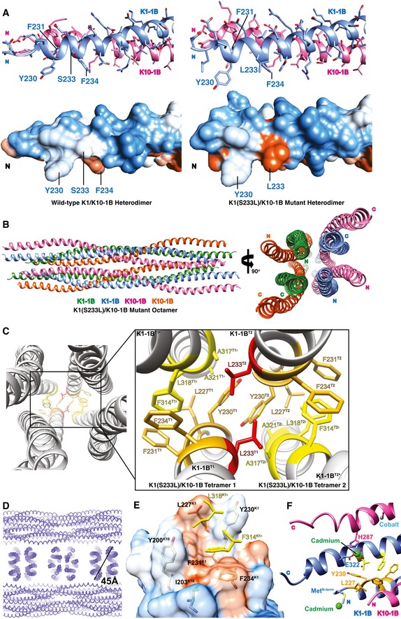
- The N‐terminus of the wild‐type K1/K10‐1B (left) and mutant K1S233L/K10‐1B (right) heterodimer structures is depicted as a ribbon (top) and molecular surface (bottom). Both S233K1 and S233LK1 are surface‐exposed, but S233LK1 generates a new hydrophobic surface patch compared to wild‐type S233K1.
- Crystal structure of K1S233L/K10‐1B octamer presented as a ribbon diagram.
- Close‐up view of the biochemical interactions between two K1/K10 tetramers (T1, T2) caused by the L233K1 mutation (red). L233K1 mediates hydrophobic assembly of the octamer by interacting with five residues from the opposing tetramer: Y230K1′, L233K1′, F234K1′, F314K1′, and A317K1′.
- Section of the K1S233L/K10‐1B crystal lattice demonstrating “pseudo‐tonotubular” structures (corresponding to the octamer) with diameter of 45 Å.
- One end of the K1S233L/K10‐1B tetramer structure depicting L227K1 interacting with L318K1′ to form the N‐terminal boundary of the hydrophobic pocket. The hydrophobic pocket from one dimer is depicted as a transparent molecular surface and colored according to hydrophobic potential (orange, hydrophobic; white to blue, polar); only the anchoring knob residues from the partner dimer are shown (yellow sticks).
- Cadmium ions (green spheres) bound to the N‐terminal methionine of K1‐1B and to C‐terminal residues E322K1 and H287K10 caused small structural changes at the termini (e.g., position of L227K1) compared to the S233LK1 mutant structure. Given its higher resolution and absence of heavy atoms, the mutant structure likely represents the more accurate and physiologic positioning of L227K1.
The increased hydrophobic surface potential created by S233LK1 mutation did not alter heterodimer or tetramer formation, but rather altered how tetramers interacted with each other (Fig 4B). This explains why the K1S233L/K10‐1B structure was determined as an octamer. Specifically, L233K1 from one tetramer bound to five residues from a different tetramer (the aromatic portion of Y230K1′, L233K1′, F234K1′, F314K1′, and Ala317K1′) to drive hydrophobic assembly of an octamer (Fig 4C). Due to the anti‐parallel symmetry of the tetramer, the same interactions by L233K1 occur at both ends of the octamer. L233K1 closely interacts with itself, L233K1′ (~ 3.8 Å), and Ala317K1′ (~ 3.9 Å). L233K1 additionally interacts with three aromatic residues over slightly longer distances: 4.3 Å (F314K1′), 4.8 Å (Y230K1′), and 5.5 Å (F234K1′). All three of these aromatic residues are involved in the anchoring knob/hydrophobic pocket mechanism of tetramer assembly. As two tetramers bind in the K1S233L/K10‐1B octamer, Y230 from one hydrophobic pocket binds with Y230 from the adjacent pocket (Fig 4C).
Examination of K1S233L/K10‐1B crystal lattice packing revealed a repetitive arrangement of a circular structure (the K1S233L/K10‐1B octamer; Fig 4D). At first glance, it appears the octamer mimics the tonotubular keratin observed under electron microscopy from EPPK skin. The diameter of the octamer, however, is only ~ 45 Å (4.5 nm), which is about one‐tenth the diameter of the observed in vitro tonotubular keratin (430 Å or 43 nm; Wevers et al, 1991). Hence, we refer to the octamer as pseudo‐tonotubular keratin.
Comparing wild‐type K1/K10‐1B and mutant K1S233L/K10‐1B tetramer structures, the major interactions between the hydrophobic pocket and anchoring knob, as described above for the wild‐type structure, are preserved in the mutant. However, there are additional features in the higher resolution mutant structure that better characterize the anchoring knob/hydrophobic pocket mechanism for tetramer assembly. First, the L227K1 side chain occupies a position much closer to L318K1′, forming the N‐terminal wall of the hydrophobic pocket and stabilizing the anchoring knob via interactions with L318K1′ (L318′ Cδ1 to L227 Cβ distance decreases from 4.7 to 3.9 Å; L318′ Cδ1 to L227 Cδ2 distance decreases from 6.0 to 4.8 Å; L318′ Cδ1 to L227 Cδ1 distance decreases from 7.1 to 3.6 Å; Fig 4E). The conformation of L227K1 appears to be altered by cadmium binding of the N‐terminal methionine in the wild‐type K1/K10‐1B structure (Fig 4F); this does not occur in the K1S233L/K10‐1B mutant structure because its crystallization condition did not contain cadmium. Second, there are two K10 residues, Y200K10 and I203K10, that in the mutant structure are < 4.3 Å away from F314K1′ and L318K1′ (Fig 4F); they are ~ 5 Å away in the wild‐type structure. These conformational differences are not a direct consequence of the K1S233L mutation itself, but rather local structure perturbations from cadmium binding at the N‐terminus of K1 (N‐terminal methionine) and C‐terminus of K1/K10 (E322K1 and H287K10) in the wild‐type K1/K10‐1B tetramer crystals (Fig 4F).
One K10 helical ridge hydrophobic residue (L236) is not considered part of the hydrophobic stripe because it functions differently than the stripe residues. All 10 K10 residues we define above as “hydrophobic stripe” contribute to tetramer formation by binding K1 residues from the partner heterodimer. L236K10 exists at the interface between K10 helices in the center of the 1B tetramer structure, and thus, it is involved in K10‐K10′ interactions. In the wild‐type K1/K10‐1B structure, L236K10 is ~ 4.9 Å away from its closest hydrophobic neighbor (L244K10′); however, in the mutant K1S233L/K10‐1B structure L236K10 and L244K10′ are ~ 4.0 Å apart signifying this interaction could have a role in K10‐K10′ stabilization in the tetramer (Fig 2F).
Structural modeling of F231LK1 and R267YK1 mutations
Literature on EPPK patients with tonotubular keratin references two additional mutations: a pathogenic F231LK1 mutation causing EPPK and tonotubular keratin (Grimberg et al, 2009), and a non‐pathogenic R267YK1 mutation in a British control subject with no skin disease (Terron‐Kwiatkowski et al, 2006). To explain the discrepancy in pathogenicity between these mutations at a structural level, the wild‐type K1/K10‐1B crystal structure was used to model F231LK1 and R267YK1 mutations. The lack of pathogenicity for R267YK1 is the most straightforward of the two; R267 occupies a solvent‐exposed position in the central aspect of the K1‐1B coil that is not involved in heterodimer, tetramer, or octamer formation (Fig 5A). R267YK1 can be accommodated without major structural consequence; thus, it is more appropriate to consider it a normal variant.
Figure 5. Mutations of the K1 anchoring knob abolish K1/K10‐1B tetramer formation.
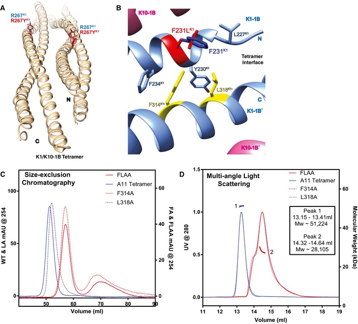
- R267K1 occupies a solvent‐exposed position in the center of the K1‐1B coil (blue); mutation to tyrosine (red) is not predicted to interfere with K1/K10 dimer or tetramer assembly.
- F231K1 (dark blue) lies at the tetramer interface and forms part of the hydrophobic pocket that binds the anchoring knob (yellow) in K1/K10‐1B tetramer assembly. Mutation of F231K1 to leucine (red) alters this position's interactions with F314K1′ and L318K1′ of the anchoring knob; the structural model suggests a weakening of interactions which could cause disruption of the anchoring knob/hydrophobic pocket tetramer assembly mechanism.
- Gel filtration analysis of purified A11 K1/K10‐1B tetramer compared to two single anchoring knob mutants (K1F314A and K1L318A) and a double anchoring knob mutant (K1F314A + L318A, FLAA) demonstrated the K1F314A mutation along with the FLAA double mutant abolished tetramer formation.
- Multi‐angle light scattering was used to verify that the molecular weight of the K1L318A mutant corresponded with the purified A11 wild‐type K1/K10‐1B tetramer, whereas both the K1F314A and FLAA mutants had molecular weights of a heterodimer.
F231LK1 alters the structure of the hydrophobic pocket that binds the anchoring knob in K1/K10‐1B tetramer assembly. F231LK1 changes the parameters of interaction with the key anchoring knob residues, F314K1′ and L318K1′ (Fig 2B and D). Specifically, the interaction distance between L318K1′ and mutant L231K1 is ~ 1.6 Å longer (4.9 Å) compared to wild‐type F231K1 (3.3 Å; Fig 5B). The closest interaction distance between F314K1′ and mutant L231K1 (3.4 Å) is unchanged compared to wild‐type F231K1 (3.4 Å), but F314K1′ loses its interactions with the F231 aromatic ring. Together, the modeling data suggest mutant L231K1 has weakened interactions with F314K1′ and L318K1′, potentially leading to pathogenic disruption of the anchoring knob/hydrophobic pocket tetramer assembly mechanism.
Mutation of both anchoring knob residues to alanine abolishes 1B tetramer formation
To validate our analysis of the K1/K10‐1B wild‐type structure, the K1S233L/K10‐1B mutant structure, and the K1F231L/K10‐1B structural model, we mutated the K1 anchoring knob residues to alanine and assessed the effect on tetramer formation. The double mutation F314AK1 + L318AK1 (FLAA) led to complete loss of K1/K10‐1B tetramer formation as assessed by gel filtration (Fig 5C) and multi‐angle light scattering (Fig 5D). Similarly, the individual mutation F314AK1 (FA) abolished tetramer complex formation compared to wild‐type K1/K10‐1B. In contrast, the individual mutation L318AK1 (LA) did not abolish K1/K10‐1B tetramer formation.
Electron microscopy demonstrates knob mutation is detrimental to IF assembly in three IF systems
To take our mutation analysis further, we determined whether the K1FLAA mutation could also affect intermediate filament assembly of full‐length proteins (recombinantly produced and purified). To assess intermediate filament assembly, negative‐stain electron microscopy was used (Fig 6). Full‐length wild‐type K1 and K10 were assembled into K1/K10 filaments under identical parameters and conditions (e.g., 10 min of assembly time) as full‐length K1FLAA mutant with K10. The K1FLAA mutation caused a significant reduction in the number and length of filaments formed (Fig 6A). The fewer, shorter filamentous structures visible for K1FLAA suggest that loss of the anchoring knob in K1 generates instability at the tetramer and unit‐length‐filament level that precludes formation of normal wild‐type filaments.
Figure 6. Anchoring knob mutation disrupts IF assembly for three IF systems.
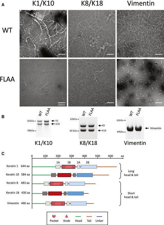
- Negative‐stain electron microscopy (EM) images comparing wild‐type (WT) and anchoring knob mutant (FLAA) filament formation for full‐length K1/K10, K8/K18, and vimentin. The duration of filament assembly was 10 min for all three IF systems. Double mutation (FLAA) of F314A + L318A in K1, F223A + L227A in K8, and F233A + L237A in vimentin causes detrimental effects on K1/K10, K8/K18, and vimentin IF assembly, respectively. The FLAA filaments are fewer in number and shorter in length despite IF assembly and EM protocols identical to the WT. These data strongly indicate the anchoring knob interaction with the hydrophobic pocket plays an important structural role in stabilizing the IF tetramer, unit‐length filament, and intact filament. The experiments were independently replicated twice.
- Coomassie‐stained SDS–PAGE demonstrating purified, recombinant wild‐type (WT) and mutant (FLAA) full‐length proteins for K1/K10 (left), K8/K18 (center), and vimentin (right) used in this EM analysis.
- Illustration of the domain organization for the IF proteins in this EM experiment in order to highlight the differences in overall protein length, the length of the heads and tails, and the dimerization state (hetero‐ vs. homo‐). The location of the hydrophobic pocket and anchoring knob at the N‐ and C‐termini of helix 1B for K1, K8, and vimentin is noted.
Since multiple sequence alignment and homology modeling suggested the anchoring knob is conserved among type II and type III IFs (see Figs 7 and 8, and Discussion), we additionally examined whether FLAA mutation altered filament assembly in two other IF systems (K8/K18 and vimentin; Fig 6B). Full‐length recombinant wild‐type K8 and K18 were assembled into K8/K18 filaments under identical parameters and conditions as full‐length K8FLAA mutant (F223A + L227A) with K18. K8FLAA had similar effect as K1FLAA on filament formation, causing a reduction in number and length of filaments formed (Fig 6A). Full‐length recombinant vimentin (which forms homodimers) was assembled into vimentin filaments under identical parameters and conditions as full‐length vimentinFLAA mutant (F233A + L237A). VimentinFLAA was unable to form short or long filamentous structures, and appeared arrested at the unit‐length‐filament stage of IF assembly. In summary, EM studies demonstrate that loss of knob structure has a damaging impact on IF assembly (the rate of and/or the length of) across IF types (type II vs. type III), for keratins with long heads and tails (K1/K10), for keratins with short heads and tails (K8/18), and for heterodimeric and homodimeric (vimentin) IF proteins (Fig 6C).
Figure 7. Comparison between the K1/K10‐1B A11 heterotetramer and the vimentin‐1B A11 homotetramer.
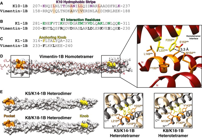
- Sequence alignment between the K10‐1B hydrophobic stripe (10 residues colored purple) and the corresponding vimentin‐1B region demonstrates that only two of five K10 hydrophobic residues (orange background) are identical (A169vim) or similar (V173vim) in vimentin. Four out of five non‐hydrophobic residues in the K10 stripe are identical or similar in vimentin.
- Of 12 K1 interaction residues (green), 10 are identical or similar in vimentin (bold); Y295K1 and A303K1 are the exceptions.
- The K1‐1B anchoring knob is identical to that in vimentin 1B: F233vim and L237vim (bold) are homologous to F314 and L318 in K1 (yellow).
- Structural representation of vimentin‐1B A11 homotetramer (PDB Code 3UF1). (Left) One homodimer is shown as a white molecular surface with the N‐terminal hydrophobic pocket colored orange and the C‐terminal anchoring knob colored yellow. The partner homodimer is shown as a maroon chain trace with the relevant anchoring knob and hydrophobic pocket residues shown as yellow and blue sticks, respectively. (Right) Zoomed‐in image of the anchoring knob/hydrophobic pocket mechanism of vimentin homotetramerization. L149, Y150, and E153 from one helix and M154 from the homodimer partner helix form the pocket (orange) bound by F233 and L237 (yellow). M154vim is positioned closest to F233vim (3.32 Å), followed by E153 (3.58 Å), Y150 (4.28 Å), and L149 (5.0 Å), suggesting that F233vim interactions with M154vim and E153vim are important for vimentin‐1B tetramerization.
- The K1/K10‐1B tetramer structure was used as a template to model the K5/K14‐1B and K8/K18‐1B structures to demonstrate that the conservation of the anchoring knob/hydrophobic pocket mechanism exists among type II keratins as well as type III IFs like vimentin.
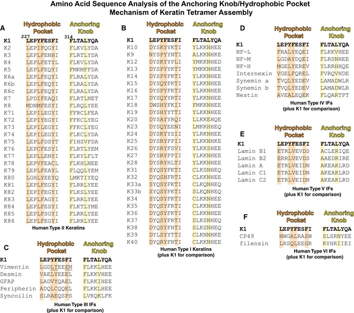
Figure 8. Multiple sequence alignments of the hydrophobic pocket and anchoring knob regions of helix 1B for all six types of intermediate filaments.
-
AThe hydrophobic pocket and anchoring knob sequences are highly conserved in type II keratins; these structural motifs utilize bulky hydrophobic and aromatic residues. Orange (pocket) and yellow (knob) background highlights mark positions critical for K1‐mediated K1/K10‐1B tetramer assembly.
-
BConsistent with structural analysis of K1/K10‐1B showing K1‐1B contributes both the hydrophobic pocket and anchoring knob residues involved in tetramer formation, type I keratins do not conserve either the pocket or knob.
-
CType III IFs, except for syncoilin, mostly conserve the anchoring knob sequence; desmin and glial fibrillary acidic protein (GFAP) substitute leucine in the distal position with other hydrophobic residues (valine and isoleucine, respectively). As for the hydrophobic pocket, type III IFs do not conserve the K1 sequence, particularly at the distal phenylalanine position. However, structural analysis of a vimentin homotetramer demonstrated a hydrophobic pocket exists and binds an anchoring knob. The critical point is that the sequence, residue positions, and manner of pocket formation differ between type III IFs and type II keratins. The residues involved in pocket formation for vimentin are underlined.
-
DType IV IFs have a vimentin‐like hydrophobic pocket, but lack a bulky hydrophobic residue at the knob position equivalent to L318K1. Our anchoring knob mutation studies suggest a proximal phenylalanine or tyrosine is sufficient for 1B tetramer formation.
-
E, FThe lamins (type V IFs) and eye lens IFs (type VI) do not conserve the K1 knob/pocket sequences.
Discussion
The wild‐type K1/K10‐1B tetramer and mutant K1S233L/K10‐1B octamer crystal structures provide key insights into human keratin tetramer assembly in the A11 mode of axial alignment and illustrate how a pathogenic mutation associated with EPPK can disrupt normal tetramer interactions. This work addresses the lack of atomic resolution structural data for the keratin intermediate filament (KIF) assembly mechanism. KIFs are more than ever implicated in cellular processes and functions beyond structural and mechanical integrity (Loschke et al, 2015). Many human diseases caused by keratin mutation do not affect heterodimer structure, but rather alter or disrupt KIF assembly; this creates a need for experimentally determined high‐resolution structures focused on understanding KIF assembly.
Our structural data, as well as gel filtration and light scattering studies demonstrating K1/K10‐1B exists as a tetramer in solution prior to crystallization, give strong support to the previously proposed A11 alignment of the K1/K10‐1B tetramer (Steinert et al, 1993a; Steinert et al, 1993b). First, the K1/K10‐1B tetramer is consistent with cross‐linking studies predicting A11 alignment. The cross‐linking data by Steinert and colleagues provide an important means to correlate and validate IF domain packing in crystal lattices with the packing observed in filaments. They identified five cross‐linked tryptic peptides from mouse K1/K10 filaments mapped to helix 1B (Steinert et al, 1993a); all five lysine pairings can be explained by structural proximity in the human K1/K10‐1B tetramer structure (Fig EV2A and B). Second, Coulombe and colleagues identified a hydrophobic stripe on type I keratins during K6/K16/K17 modeling (Bernot et al, 2005); as hypothesized, the K10 hydrophobic stripe participates in K1/K10‐1B tetramer formation. However, the stripe's role in A11 tetramer formation proved more complex than anticipated: It was one of the four key regions defining tetramer assembly, it did not self‐associate, and its main interactions occurred with K1 residues. Importantly, prior mutation of hydrophobic stripe residues in mouse K16 and K17 did not significantly affect mature filament formation in vitro (Bernot et al, 2005); this is in contrast to anchoring knob mutants of human K1, K8, and vimentin which impaired in vitro filament formation for K1/K10, K8/K18, and vimentin (Fig 6). Third, the A11 alignment validates the hypothesis that the S233LK1 mutation alters heterodimer and/or filament interactions through the creation of aberrant surface hydrophobicity, ultimately leading to tonotubular keratin (Terron‐Kwiatkowski et al, 2006). The K1S233L/K10‐1B structure validated this by showing S233LK1 caused tetramer aggregation through specific hydrophobic interactions with residues involved in the tetramer assembly mechanism.
Figure EV2. Mapping of cross‐linked mouse K1/K10‐1B tryptic peptide data onto the human K1/K10‐1B tetramer structure.
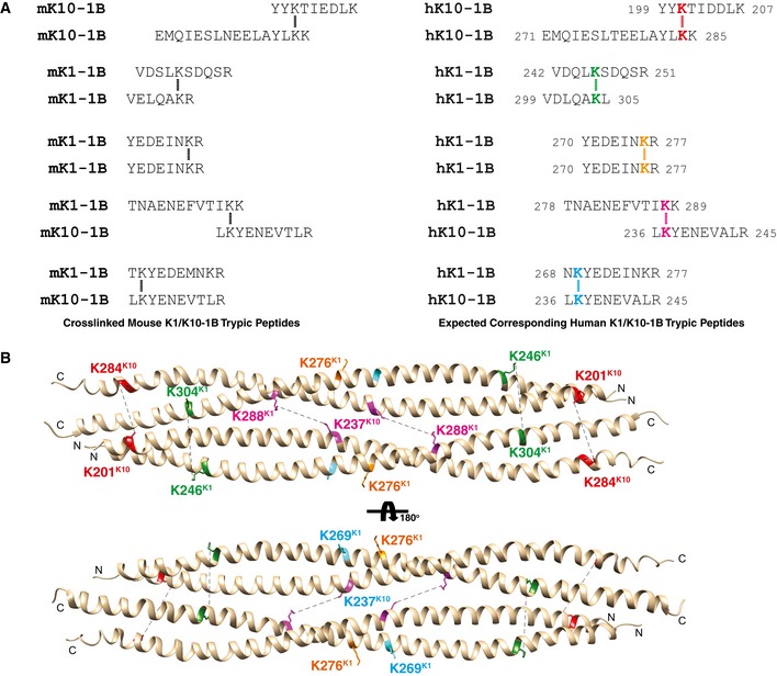
- (Left) Five cross‐linked mouse K1/K10‐1B tryptic peptides previously described (Steinert et al, 1993a). (Right) The expected corresponding cross‐links in human K1/K10‐1B. Cross‐linked lysines are color‐coded for easier identification in panel (B). Lysine 237 from K10 appears in two distinct cross‐linked species (magenta and blue).
- Crystal structure of human K1/K10‐1B with backbone presented in ribbon diagram and pertinent lysine side chains as sticks. Steinert and colleagues used DST (disulfosuccinimidyl tartrate) as cross‐linking reagent (cross‐link arm of 0.6 nm); this means lysines within ˜ 15 Å can cross‐link. In the structure, K288K1 and K237K10 are 13.4 Å apart. K201K10 and K284K10 are 16.8 Å apart, and K246K1 and K304K1 are 21.6 Å apart: Both of these lysine pairings are structurally adjacent and can be expected to form the observed lysine cross‐links when factoring in protein dynamics in solution (i.e., the crystal structure is a static picture of a protein moment in time, but in solution, the lysine side chains, based on proximity in the tetramer structure, should be able to move into a conformation amenable to cross‐link formation with DST). It is also important to note Steinert and colleagues had peptide cross‐links of various oligomer sizes; thus, the presence of an octamer species (two tetramers) will influence the cross‐links observed. Both K269K1 and K276K1 are surface‐exposed residues that structurally appear to require the higher order oligomer to explain the observed cross‐links. The key point is the positions of the lysines in the wild‐type K1/K10‐1B tetramer structure are consistent with the biochemical cross‐linking data.
Our structural analysis comparing the K1/K10‐1B heterotetramer with the vimentin‐1B A11 homotetramer (a type III IF; Aziz et al, 2012) revealed major differences between the determinants of keratin and vimentin tetramer formation while confirming that the anchoring knob/hydrophobic pocket mechanism of tetramer assembly is generally conserved. Besides the obvious difference that vimentin forms homodimers rather than heterodimers like the keratins, vimentin does not contain a hydrophobic stripe aiding tetramer formation. The K10 hydrophobic stripe contains five key hydrophobic residues with interactions (to K1′) that stabilize the 1B tetramer; only one hydrophobic residue is conserved (A218K10) and one similar (L222K10 to valine) in vimentin (Fig 7A). Vimentin conserves none of the four critical leucine residues in the K10 hydrophobic stripe. Of the 12 K1 interaction residues, five are completely conserved and another five are similar in vimentin (Fig 7B). In contrast to the K10 hydrophobic stripe and K1 interaction residues, the C‐terminal anchoring knob is entirely conserved in vimentin helix 1B (Fig 7C). Vimentin's F233 and L237 form an anchoring knob homologous to F314 and L318 in K1. Like K1/K10, the vimentin anchoring knob binds into a hydrophobic pocket at the N‐terminus of a neighboring vimentin‐1B homodimer. Vimentin's hydrophobic pocket, however, is formed differently than K1. There are four key vimentin residues that form the hydrophobic pocket: L149, Y150, E153 (the aliphatic portion), and M154. Unlike K1/K10‐1B, where all of the hydrophobic pocket is formed by K1 residues (and not K10), vimentin's hydrophobic pocket is formed by residues from both homodimer helices. L149, Y150, and E153 are on one helix, and M154 comes from the homodimer partner helix (Fig 7D). Our identification of the anchoring knob/hydrophobic pocket mechanism in vimentin‐1B tetramer formation may explain why several prior vimentin crystal structures failed to show tetramerization: The vimentin construct either did not contain the N‐terminal sequence needed to form a complete hydrophobic pocket (PDB Codes 3SWK and 4YPC) or lacked the C‐terminal sequence containing the anchoring knob (PDB Codes 3SSU and 3S4R; Chernyatina et al, 2016, 2012). Structural models of K5/K14‐1B and K8/K18‐1B illustrate anchoring knob/hydrophobic pocket conservation like K1/K10‐1B and vimentin 1B (Fig 7E).
The importance of the anchoring knob/hydrophobic pocket mechanism to higher order KIF formation is demonstrated by our mutational studies on the anchoring knob (Figs 5 and 6); these data are validated further by multiple sequence alignment. For all type II keratins, including the hair and nail keratins, the anchoring knob positions are highly conserved: Position 314K1 is conserved as phenylalanine in 25/26 type II keratins (K80 has leucine); position 318K1 is conserved as leucine in 23/26 type II keratins (K5 has phenylalanine, K75 valine, and K80 isoleucine) (Fig 8). Similarly, the hydrophobic pocket is highly conserved: Positions 227K1 and 230K1 are conserved as large hydrophobic residues in 26/26 and 25/26 type II keratins, respectively (K76 has cysteine at 230); position 231K1 is conserved as an aromatic residue in 22/26 type II keratins (K71, K73, K74, and K77 have leucine); and position 234K1 is conserved as an aromatic residue in 23/26 type II keratins (K3 has histidine, K7 glutamine, and K78 cysteine; Fig 8A).
The 28 type I keratins do not have a hydrophobic pocket or anchoring knob (Fig 8B). There are no large hydrophobic residues at the analogous Y230K1 position, 20/28 residues at the analogous F234K1 position are threonine, and 25/28 residues at the analogous L318K1 position are asparagine. Except for syncoilin (no similarity), the primary sequences of type III IFs indicate they contain a vimentin‐like hydrophobic pocket and a K1‐ and vimentin‐like anchoring knob (Fig 8C). Type IV IFs appear to have a vimentin‐like hydrophobic pocket and an aromatic or hydrophobic residue at the corresponding F314K1 knob position (which was the essential site in our mutational studies), but they lack a bulky hydrophobic residue at the equivalent L318K1 knob position (Fig 8D). Type V IFs (lamins) and the type VI IFs (eye lens) do not have sequence resemblance to either the K1 pocket or knob (Fig 8E and F). Together, these findings suggest that this mechanism of higher order A11 intermediate filament assembly is very similar for several IF types, but is not identical across all IF types.
The molecular surfaces of IFs contain features critical to their assembly and function. Perhaps the most important finding from the previous K1/K10‐2B heterodimer structure was that only a small number of residue differences are needed to significantly alter the shape and chemistry of the keratin surface because most of the unique residues concentrate along the outer helical ridges of the coiled‐coil (Bunick & Milstone, 2017). This holds true for K1/K10‐1B as well (Figs EV3A and B, and EV4A–D). An important question raised by the K1/K10‐2B structure was whether the identified surface pockets had relevant biological function. The K1/K10‐1B dimer and tetramer structures confirmed that a surface pocket (the N‐terminal hydrophobic pocket) visualized in the heterodimer structure served as a receptacle for another part of the complex (the anchoring knob) to help align K1/K10 for higher order assembly (Fig EV5A and B). This validates the concept that keratins contain molecular surface pockets that are biologically relevant, in this case for filament assembly, but in other cases possibly for association with non‐keratin proteins.
Figure EV3. Mapping of amino acid sequence differences between K1/K5 and K10/K14 onto the molecular surface of the wild‐type K1/K10‐1B structure.
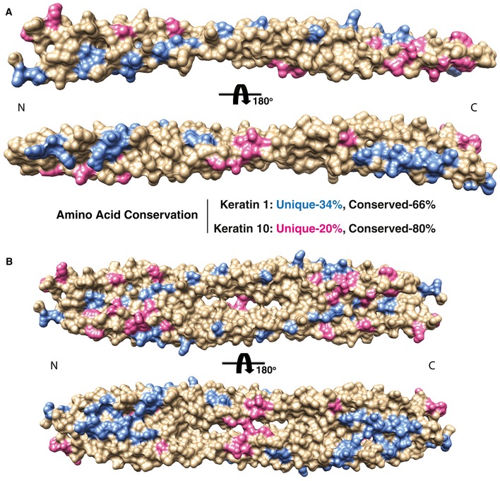
- Residues in K1 (blue) and K10 (pink) that are unique (non‐identical) compared with basal keratins K5 and K14, respectively, are mapped onto the K1/K10‐1B heterodimer structure (represented as a molecular surface). Residues that are conserved/identical are tan. K1 residues that are non‐identical to K5 are colored blue, while K10 residues that are non‐identical to K14 are colored pink. The majority of unique residues for K1 and K10 align along the outer aspect of the helices. The majority of the conserved residues lie along the dimer interface. This distribution of unique residues enables keratins to maximize the diversity of surface properties, such as surface charge and shape, while maintaining a common structural coiled‐coil fold.
- The same mapping and coloring of unique residues as in panel (A) is applied to the K1/K10‐1B tetramer structure.
Figure EV4. Comparison of K1/K10‐1B and vimentin‐1B tetramer structures.
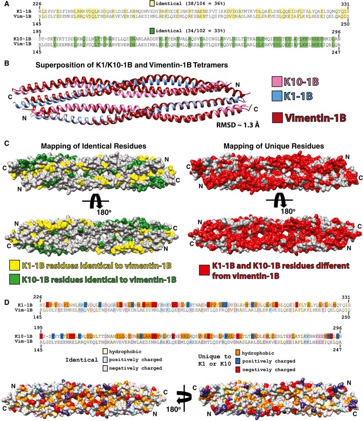
- Sequence alignments of K1‐1B and K10‐1B each with vimentin 1B. There is 36% sequence identity between K1‐1B and vimentin 1B (yellow), and 33% sequence identity between K10‐1B and vimentin 1B (green).
- The wild‐type K1/K10‐1B and vimentin‐1B (PDB Code 3UF1) tetramer structures were superimposed and have a RMSD of 1.3 Å.
- The keratin residues that are identical to vimentin 1B were mapped onto a molecular surface representation of the K1/K10‐1B tetramer structure and colored yellow (K1‐1B) or green (K10‐1B). All K1/K10‐1B residues not identical to vimentin 1B were mapped onto the molecular surface of the K1/K10‐1B tetramer structure and colored red, demonstrating a significant proportion of the K1/K10‐1B molecular surface will have differences in chemistry compared to vimentin 1B.
- To further illustrate how the molecular surface of the K1/K10‐1B tetramer differs from vimentin 1B, both identical residues (lighter colors) and residues unique to K1 or K10 (darker colors) were divided into hydrophobic, positively charged, and negatively charged groups and mapped onto the K1/K10‐1B tetramer molecular surface. The majority of the unique hydrophobic residues are located in the central region of the 1B domain, whereas the unique charged residues appear evenly distributed. Definitions of residues were acidic (D, E), basic (K, R), and hydrophobic (A, F, I, L, M, P, V, W).
Figure EV5. Observed electron density throughout the K1S233L/K10‐1B crystal structure.
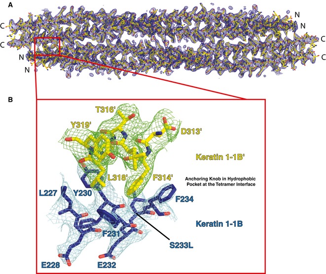
- The two K1S233L‐1B and two K10‐1B molecules composing the K1S233L/K10‐1B tetrameric crystal structure are depicted as yellow sticks in electron density (blue, contoured at 0.8σ). A red box highlights one anchoring knob/hydrophobic pocket site in the symmetric, anti‐parallel tetramer.
- A close‐up view of one anchoring knob/hydrophobic pocket site in the K1S233L/K10‐1B crystal structure (K10 residues have been omitted for clarity). The K1‐1B containing the hydrophobic pocket is depicted as blue sticks in electron density (cyan, contoured at 0.8σ). The K1‐1B′ from the partner heterodimer contains the anchoring knob and is depicted as yellow sticks in electron density (green, contoured at 0.8σ). N, N‐terminus; C, C‐terminus.
The observation of a highly acidic groove across the molecular surface of the K1/K10‐1B tetramer, but not the dimer, illustrates another important concept: Higher order assemblies of keratins may contain new surface features that are not present at the heterodimer level. In other words, some keratin structural features that may be critical for filament assembly or interaction with non‐keratin proteins cannot be discovered without structures of higher order keratin complexes. The acidic groove in the K1/K10‐1B tetramer extends the full length of the 1B helix, raising questions about its biological purpose. While it could help protofibril/unit‐length‐filament formation, an alternative hypothesis is that it serves as the binding site for the non‐keratin, positively charged protein, filaggrin. The atomic resolution mechanism by which filaggrin, short for “filament aggregating protein”, binds keratin is unknown; Steinert and colleagues proposed an “ionic zipper hypothesis” (Mack et al, 1993). The tetramer face opposite the long acidic groove also contains two smaller grooves and a larger pocket; further studies to understand the purpose of each surface feature are critical to elucidating the keratin structure–function paradigm.
The biochemical and structural studies of K1S233L/K10‐1B demonstrate how a single missense mutation relevant to human skin disease can alter the behavior of KIFs. In this case, K1S233L caused erroneous hydrophobic interactions between the mutant L233 and key residues involved in the anchoring knob/hydrophobic pocket mechanism of tetramer assembly. Even though the K1S233L/K10‐1B structure did not fully recapitulate tonotubular keratin, it did recapitulate aberrant association of K1/K10 into higher order aggregates. The most likely reason why complete tonotubular keratin was not observed is that we worked with only the 1B subdomain of K1/K10 [flexible full‐length keratins are problematic for crystallization (Strelkov et al, 2001)]; the other portions of intact K1/K10 must play a role in transforming the aberrant tetramer aggregation into a tubular morphology.
The crystal structures of the wild‐type keratin 1/10‐1B tetramer and the mutant K1S233L/K10‐1B octamer described here establish a foundation for understanding the molecular determinants of KIF assembly at atomic resolution. The mechanism of A11 axial alignment in the keratin 1B region utilizes precise molecular interactions, which raises questions as to how KIFs utilize other predicted modes of alignment, such as the A22, ACN, or A12 modes. We propose a simplified model where the A11 tetramer is the building block for KIF assembly based on its strength, stability, and molecular precision as observed in our data and as observed in previous studies (Aziz et al, 2012; Herrmann & Aebi, 2016; Kim et al, 2018; Mücke et al, 2004; Premchandar et al, 2016; Steinert et al, 1993a; Steinert et al, 1993b; Fig 9). Both the A22 and ACN alignments essentially describe how an A11 tetramer packs onto itself during the longitudinal elongation of tetramers into a protofilament (i.e., establishing length). Thus, we propose A22 and ACN describe packing interfaces of the A11 building block more than they represent their own distinct mode of alignment. Our EM data support this concept: Knob mutation causes misalignment and/or instability in the A11 tetramer, which impairs its ability to pack properly using A22 and ACN interactions, ultimately reflected in aberrant filaments. A12 on the other hand is a unique alignment mode that describes the side‐to‐side packing of tetramers (i.e., establishing width) through largely the helix 1B–helix 2B interaction. The orthogonal relationship between the A12 mode and the A11/A22 modes is supported by a recent vimentin‐1B structure (Pang et al, 2018). Our model also illustrates how the A12 interactions may cause the pitch or spiraling behavior observed in prior electron microscopy (Aebi et al, 1983) and cross‐linking studies (Steinert et al, 1993a,c). We emphasize that the molecular surfaces of keratin occluded in A11 tetramer formation and elongation are completely different than the surfaces needed for A12 alignment.
Figure 9. Model for keratin intermediate filament assembly based on K1/K10‐1B tetramer structures.
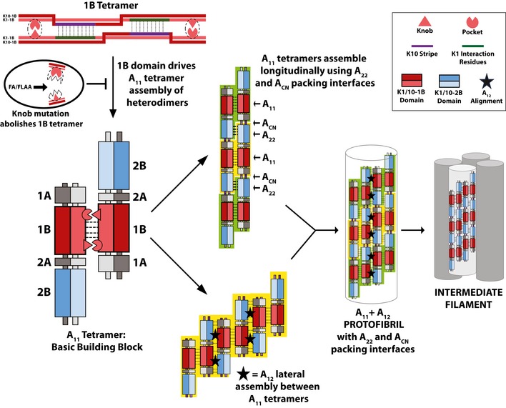
Analysis of the K1/K10‐1B and K1S233L/K10‐1B tetramer structures identified a critical anchoring knob/hydrophobic pocket mechanism that orients, drives assembly of, and stabilizes the A11 tetramer. The importance of this mechanism was demonstrated by studies showing anchoring knob mutants failed to form 1B‐tetramers and formed aberrant full‐length IFs on EM. The strength of the anchoring knob/hydrophobic pocket mechanism in the keratin 1B region suggests that the A11 tetramer is the basic building block for filament formation, consistent with established literature. The helix 2B overhang in the A11 tetramer enables multiple A11 tetramers to assemble longitudinally so that the 2B helices are in phase (the A22 packing interface) and the head and tail regions overlap (the ACN packing interface). Lateral assembly of A11 tetramers occurs by a distinct mode of alignment, the A12 mode, where the 1A‐1B region from one tetramer and the 2A‐2B region from an adjacent tetramer pack anti‐parallel (black star). Together, the A11 and A12 modes of alignment are used by A11 tetramers to generate a protofibril; four protofibrils then assemble to form a 10‐nm intermediate filament (Steven et al, 1982, 1983; Aebi et al, 1983; Herrmann & Aebi, 1999).
It is evident from our model, as well as in cross‐linking studies (Steinert et al, 1993a,b,c), that coils 1A and 2A also play a role in A11 tetramer stabilization and intermediate filament formation. This was confirmed by hydrogen–deuterium exchange experiments on vimentin filament assembly; the stability of coils 1A and 2A increased during filament formation (Premchandar et al, 2016). Importantly, hydrogen–deuterium exchange also identified the N‐ and C‐termini of vimentin coil 1B as the most stable segments of the entire vimentin tetramer. The biochemical, structural, and electron microscopy data we present here provide a molecular basis for why this occurs in multiple IF systems: Symmetric knob/pocket interactions at the termini of coil 1B enhance tetramer formation and filament stability.
In conclusion, to fully characterize intermediate filament formation, additional atomic resolution structures of KIF assemblies are needed. It will be important to focus on the biochemical determinants of alignment within other keratin subdomains (e.g., 1A, 2A, 2B and head/tail domains) and for the different packing interfaces (A22, ACN) and modes of axial alignment (A11, A12).
Materials and Methods
Protein production and purification
pET‐based plasmids of K1‐1B (res. 226–331), K10‐1B (res. 195–296), K1S233L‐1B (res. 226–331), and the K1‐1B mutants F314A, L318A, and F314A+L318A were purchased from GenScript (Piscataway, NJ). Proteins were expressed in Escherichia coli strain BL21(DE3) (Agilent Technologies, Santa Clara, CA) at 37°C in Luria Broth Miller (EMD Millipore, Burlington, MA). Protein expression was induced with 1 mM isopropyl‐D‐thiogalactopyranoside (IPTG) and proceeded for 3–4 h. After pelleting cells by centrifugation at 2,500 × g, 10 min., at 4°C, they were suspended in 50 mM Tris–HCl buffer (pH 7.8) containing 0.5 M NaCl, 20 mM imidazole, 1% Nonidet P‐40, 6 mM MgCl2, 1 mM CaCl2, and 1× EDTA‐free protease inhibitor cocktail (Roche Diagnostics). For wild‐type heterodimer, K1‐1B cell suspension was mixed with K10‐1B cell suspension. For K1S233L mutant, K1S233L‐1B cell suspension was mixed with K10‐1B cell suspension. Both wild‐type and mutant heterodimers were purified using the same procedure. Cells were lysed by sonication on ice, followed by incubation of lysate with ~ 30 units/ml DNase I at 37°C for 15 min. The solution was centrifuged at 15,000 × g, 15 min, at 4°C. The supernatant underwent batch nickel affinity purification using previously described methods (Bunick et al, 2015). The clarified solution containing untagged heterocomplex was applied to a Superdex 75 (26/60) gel filtration column in 100 mM Tris–HCl buffer (pH 7.4) containing 0.2 M NaCl. Collected fractions were analyzed by sodium dodecyl sulfate–polyacrylamide gel electrophoresis (SDS–PAGE), and selected pooled fractions were concentrated in a 10,000 Da molecular weight cutoff centrifugal filter unit (EMD Millipore).
Multi‐angle light scattering
K1/K10‐1B (2.4 mg/ml) in 20 mM Tris–HCl buffer (pH 7.4) containing 100 mM NaCl was applied at 0.5 ml per minute to Superdex 75 gel filtration column in‐line with DAWN HELEOS II light scattering instrument (Wyatt Technology, Santa Barbra, CA; laser wavelength 658 nm). Data collection and analysis used Astra software (Wyatt technology) version 5.3.4.20. This procedure was repeated using K1S233L/K10‐1B (2.3 mg/ml); it was also repeated with buffer containing 200 mM NaCl using a Superdex 200 gel filtration column. Analysis of K1F314A/K10‐1B, K1L318A/K10‐1B, and K1F314A+L318A/K10‐1B was performed similarly, using 100 mM Tris–HCl buffer (pH 7.4) containing 0.2 M NaCl.
Circular dichroism
Circular dichroism (CD) measurements were made on solutions containing wild‐type K1/K10‐1B or mutant K1S233L/K10‐1B at 0.5 mg/ml in 100 mM Tris–HCl buffer (pH 7.4) containing 200 mM NaCl. A Chirascan spectrometer (Applied Photophysics, Beverly, MA) was used to scan the samples in a 0.1‐cm pathlength cuvette from wavelength 260–190 nm (2 nm/s) at 22°C.
Electron microscopy analysis of intermediate filaments
pET‐21a(+)‐based plasmids of human full‐length wild‐type K1, K1 containing F314A + L318A mutations, wild‐type K8, K8 containing F223A + L227A mutations, wild‐type vimentin, and vimentin containing F233A + L237A mutations were purchased from GenScript (Piscataway, NJ); wild‐type K10 and K18 were similarly purchased in pET‐24a(+) plasmid. K10 was expressed in E. coli BL21(DE3)pLysS cells (Invitrogen, Waltham, MA) at 20°C for 72 h using an autoinduction method (Studier, 2005). Expression of all other keratins and vimentins occurred in E. coli BL21(DE3) cells using lysogeny broth at 37°C for 3 h with 1 mM IPTG for induction. An inclusion body pellet was purified from the cells using a previous protocol (Nagai & Thøgersen, 1987) modified to include sonication at each step of pellet resuspension. Inclusion bodies were resuspended in 6 M urea solution and purified by ion exchange chromatography (Q/SP Sepharose, GE Healthcare, Marlborough, MA) as described (Coulombe & Fuchs, 1990; Paladini et al, 1996) using a 200 mM guanidine‐HCl gradient, followed by size‐exclusion chromatography (Superdex 75, GE) using 6 M urea solution. Heterodimeric complexes of K1/K10 and K8/K18, and homodimeric complex of vimentin, were made by mixing individual protein in a 1:1 molar ratio; the complexes subsequently were purified with Q sepharose using a 200 mM guanidine‐HCl gradient, and then dialyzed into 50 mM Tris–HCl buffer (pH 8.5) containing 6 M urea and 2 mM DTT. Before initiating filament assembly, all IF complexes were concentrated to 0.49 μg/μl and dialyzed into 25 mM Tris–HCl buffer (pH 8.5) containing 9 M urea and 2 mM DTT at room temperature for 4 h. K1/K10 filament formation followed established “Assembly method 4”, whereas K8/18 and vimentin filaments were assembled from established “Assembly method 1” (Herrmann et al, 2002). Filament assembly was terminated after 10 min by adding stop buffer (0.2% glutaraldehyde, 20 mM KCl, 0.7 mM Na2HPO4). Filament samples were immediately applied to a Carbon Type B on 400 mesh copper grid charged with Pelco easiGlow (Ted Pella, Redding, CA) at 25 mA for 30 s, and negatively stained using 2% aqueous uranyl acetate. Images were captured with a Talos L120C Electron Microscope from FEI (Hillsboro, OR).
Crystallization and X‐ray data collection
Sitting‐drop vapor diffusion crystallization was performed at 25°C by mixing 3 μl of protein with 3 μl of reservoir solution. X‐ray data were collected on crystals maintained at ~ 100 K using the 24‐ID‐C beamline at the Advanced Photon Source at Argonne National Laboratory. Diffraction data were processed using HKL‐2000 (Otwinowski & Minor, 1997).
Wild‐type K1/K10‐1B (23.7 mg/ml) in 100 mM Tris–HCl buffer (pH 7.4) containing 200 mM NaCl was crystallized using 100 mM HEPES buffer (pH 7.5) containing 5 mM cobalt(II) chloride, 5 mM cadmium dichloride, 5 mM magnesium chloride, 5 mM nickel(II) chloride, and 11% polyethylene glycol 3350. Crystals were soaked 1–3 min in a cryoprotectant solution containing 25% propylene glycol in mother liquor prior to flash‐freezing in liquid nitrogen. A native data set on a single crystal was collected (λ = 0.9795 Å). The crystal belonged to the trigonal space group P3121 (cell dimensions: a = 106.69 Å, b = 106.69 Å, c = 70.32 Å, α =β = 90°, γ = 120°). A second data set was collected on a different crystal from the same growth condition at the cadmium edge (λ = 1.4586 Å) and had strong anomalous signal.
Mutant K1S233L/K10‐1B (22.8 mg/ml) in 100 mM Tris–HCl buffer (pH 7.4) containing 200 mM NaCl was crystallized using 100 mM Tris buffer (pH 8.5) containing 1.5 M ammonium sulfate and 12% glycerol. Crystals were soaked 1–3 min in a cryoprotectant solution containing 27% glycerol in mother liquor prior to flash‐freezing in liquid nitrogen. One native data set on a single crystal was collected (λ = 0.9795 Å). The native crystal belonged to the hexagonal space group P6422 (cell dimensions: a = 93.29 Å, b = 93.29 Å, c = 124.74 Å, α = β = 90°, γ = 120°). A second data set was collected to ~ 2.2 Å resolution, using a different crystal from the same growth condition soaked in mercury solution, at the mercury edge (λ = 1.00841 Å) and had strong anomalous signal. The heavy atom soak was performed as follows: A K1S233L/K10‐1B crystal was transferred to a 10 μl drop of mother liquor solution containing 1 mM potassium tetraiodomercurate(II) and soaked for 1 h at room temperature. It was then transferred and soaked for 1 min in a cryoprotectant solution containing 27% glycerol in mother liquor prior to flash‐freezing in liquid nitrogen. The heavy atom crystal belonged to the hexagonal space group P6422 (cell dimensions: a = 93.62 Å, b = 93.62 Å, c = 122.74 Å, α =β = 90°, γ = 120°).
Structure determination, refinement, and analysis
Phaser‐EP (PHENIX; Adams et al, 2010) was used to fit a poly‐alanine coiled‐coil model into the mercury heavy atom data for K1S233L/K10‐1B. The mercury sites were used to align the coiled‐coil register, and the correct protein sequence was manually built. The structure was refined using PHENIX and subsequently used for molecular replacement into the wild‐type K1/K10‐1B data and the native K1S233L/K10‐1B data using MOLREP (Vagin & Teplyakov, 2010). Molecular replacement bias was reduced using a simulated annealing composite omit map generated in PHENIX for each structure. The structures underwent iterative rounds of model building (Coot; Emsley & Cowtan, 2004) and refinement (PHENIX; Adams et al, 2010) using standard geometric (bond length, bond angle) and secondary structure restraints (Table 1). The final model of the wild‐type K1/K10‐1B crystal asymmetric unit contained one K1‐1B and one K10‐1B molecule in a heterodimer complex. The biologically relevant structure in the unit cell was a tetramer composed of two K1/K10‐1B heterodimers. The final Ramachandran statistics were as follows: residues in favorable regions, 99%; in allowed regions, 0.49%; in outlier regions, 0.49%.
The final model of the K1S233L/K10‐1B mutant crystal asymmetric unit contained one K1S233L‐1B and one K10‐1B molecule in a heterodimer complex. A biologically relevant structure in the unit cell was a tetramer composed of two K1S233L/K10‐1B heterodimers; these tetramers aggregated into an octamer via K1S233L. The final Ramachandran statistics were as follows: residues in favorable regions, 100%. Electrostatics were calculated using PDB2PQR (Dolinsky et al, 2004) and Adaptive Poisson–Boltzmann Software (APBS; Baker et al, 2001). Structural analyses were performed using Coot, UCSF Chimera (Resource for Biocomputing, Visualization, and Informatics, University of California, San Francisco), WHAT IF (Vriend, 1990), ESBRI (Costantini et al, 2008), and PDBePISA (The European Bioinformatics Institute, European Molecular Biology Laboratory, UK). Figures were prepared using UCSF Chimera and Adobe Illustrator.
Author contributions
CGB designed the study. SAE and CGB conducted the biochemistry and crystallography studies, including protein purification, crystallization, and light scattering. MH collected the mutagenesis and electron microscopy data with assistance from AJH. AJH performed circular dichroism. IBL and SAE collected the synchrotron data. SAE and CGB processed and refined the crystallographic data, and performed the structural analysis. CGB wrote the manuscript. All authors approved the final manuscript.
Conflict of interest
The authors declare that they have no conflict of interest.
Supporting information
Expanded View Figures PDF
Review Process File
Acknowledgements
We thank Prof. Thomas A. Steitz (Dept. of Molecular Biophysics and Biochemistry, Yale Univ.) for providing laboratory space, equipment, and supplies for this project. We thank Bill Eliason and Dr. Jimin Wang for assistance with light scattering and heavy atom phasing, respectively. We thank Kaifeng Zhou for assistance collecting EM data. We thank Prof. Leonard Milstone (Dept. of Dermatology, Yale Univ.) for critical review of the manuscript. This work was supported by the Foundation for Ichthyosis & Related Skin Types through a Research Award (to CGB), the Yale School of Medicine Student Summer Fellowship (to SAE), and NIH/NIAMS Award K08‐AR070290 (to CGB). Aspects of this work were presented at the 2018 American Academy of Dermatology Annual Meeting (San Diego) and the 2018 International Investigative Dermatology Meeting (Orlando). Aspects of this work are protected by U.S. Patent No. 62/742,484 (to SAE and CGB) through the Yale Office of Cooperative Research.
The EMBO Journal (2019) 38: e100741
Data availability
Atomic coordinates and structure factors have been deposited in the Protein Data Bank under the accession codes 6EC0 (wild‐type) and 6E2J (mutant).
References
- Adams PD, Afonine PV, Bunkóczi G, Chen VB, Davis IW, Echols N, Headd JJ, Hung LW, Kapral GJ, Grosse‐Kunstleve RW et al (2010) PHENIX: a comprehensive Python‐based system for macromolecular structure solution. Acta Crystallogr D Biol Crystallogr 66: 213–221 [DOI] [PMC free article] [PubMed] [Google Scholar]
- Aebi U, Fowler WE, Rew P, Sun TT (1983) The fibrillar substructure of keratin filaments unraveled. J Cell Biol 97: 1131–1143 [DOI] [PMC free article] [PubMed] [Google Scholar]
- Aziz A, Hess JF, Budamagunta MS, Voss JC, Kuzin AP, Huang YJ, Xiao R, Montelione GT, FitzGerald PG, Hunt JF (2012) The structure of vimentin linker 1 and rod 1B domains characterized by site‐directed spin‐labeling electron paramagnetic resonance (SDSL‐EPR) and X‐ray crystallography. J Biol Chem 287: 28349–28361 [DOI] [PMC free article] [PubMed] [Google Scholar]
- Baker NA, Sept D, Joseph S, Holst MJ, McCammon JA (2001) Electrostatics of nanosystems: application to microtubules and the ribosome. Proc Natl Acad Sci USA 98: 10037–10041 [DOI] [PMC free article] [PubMed] [Google Scholar]
- Bernot KM, Lee CH, Coulombe PA (2005) A small surface hydrophobic stripe in the coiled‐coil domain of type I keratins mediates tetramer stability. J Cell Biol 168: 965–974 [DOI] [PMC free article] [PubMed] [Google Scholar]
- Bunick CG, Presland RB, Lawrence OT, Pearton DJ, Milstone LM, Steitz TA (2015) Crystal structure of human profilaggrin S100 domain and identification of target proteins annexin II, stratifin and hsp27. J Invest Dermatol 135: 1801–1809 [DOI] [PMC free article] [PubMed] [Google Scholar]
- Bunick CG, Milstone LM (2017) The X‐Ray crystal structure of the keratin 1‐keratin 10 helix 2B heterodimer reveals molecular surface properties and biochemical insights into human skin disease. J Invest Dermatol 137: 142–150 [DOI] [PMC free article] [PubMed] [Google Scholar]
- Chernyatina AA, Nicolet S, Aebi U, Herrmann H, Strelkov SV (2012) Atomic structure of the vimentin central α‐helical domain and its implications for intermediate filament assembly. Proc Natl Acad Sci USA 109: 13620–13625 [DOI] [PMC free article] [PubMed] [Google Scholar]
- Chernyatina AA, Guzenko D, Strelkov SV (2015) Intermediate filament structure: the bottom‐up approach. Curr Opin Cell Biol 32: 65–72 [DOI] [PubMed] [Google Scholar]
- Chernyatina AA, Hess JF, Guzenko D, Voss JC, Strelkov SV (2016) How to study intermediate filaments in atomic detail. Methods Enzymol 568: 3–33 [DOI] [PubMed] [Google Scholar]
- Costantini S, Colonna G, Facchiano AM (2008) ESBRI: a web server for evaluating salt bridges in proteins. Bioinformation 3: 137–138 [DOI] [PMC free article] [PubMed] [Google Scholar]
- Coulombe PA, Fuchs E (1990) Elucidating the early stages of keratin filament assembly. J Cell Biol 111: 153–169 [DOI] [PMC free article] [PubMed] [Google Scholar]
- Dolinsky TJ, Nielsen JE, McCammon JA, Baker NA (2004) PDB2PQR: an automated pipeline for the setup of Poisson‐Boltzmann electrostatics calculations. Nucleic Acids Res 32: W665–W667 [DOI] [PMC free article] [PubMed] [Google Scholar]
- Eldirany S, Hinbest A, Lomakin IB, Bunick CG (2018) 689 The X‐ray crystal structure of human keratin 1 with S233L mutation demonstrates mechanism of pathogenic tonotubular keratin formation leading to epidermolytic palmoplantar keratoderma. J Invest Dermatol 138: S117 [Google Scholar]
- Emsley P, Cowtan K (2004) Coot: model‐building tools for molecular graphics. Acta Crystallogr D Biol Crystallogr 60: 2126–2132 [DOI] [PubMed] [Google Scholar]
- Grimberg G, Hausser I, Müller FB, Wodecki K, Schaffrath C, Krieg T, Oji V, Traupe H, Arin MJ (2009) Novel and recurrent mutations in the 1B domain of keratin 1 in palmoplantar keratoderma with tonotubules. Br J Dermatol 160: 446–449 [DOI] [PubMed] [Google Scholar]
- Herrmann H, Aebi U (1999) Intermediate filament assembly: temperature sensitivity and polymorphism. Cell Mol Life Sci 55: 1416–1431 [DOI] [PMC free article] [PubMed] [Google Scholar]
- Herrmann H, Wedig T, Porter RM, Lane EB, Aebi U (2002) Characterization of early assembly intermediates of recombinant human keratins. J Struct Biol 137: 82–96 [DOI] [PubMed] [Google Scholar]
- Herrmann H, Aebi U (2016) Intermediate filaments: structure and assembly. Cold Spring Harb Perspect Biol 8: a018242 [DOI] [PMC free article] [PubMed] [Google Scholar]
- Kim B, Kim S, Jin MS (2018) Crystal structure of the human glial fibrillary acidic protein 1B domain. Biochem Biophys Res Commun 503: 2899–2905 [DOI] [PubMed] [Google Scholar]
- Lee CH, Kim MS, Chung BM, Leahy DJ, Coulombe PA (2012) Structural basis for heteromeric assembly and perinuclear organization of keratin filaments. Nat Struct Mol Biol 19: 707–715 [DOI] [PMC free article] [PubMed] [Google Scholar]
- Loschke F, Seltmann K, Bouameur JE, Magin TM (2015) Regulation of keratin network organization. Curr Opin Cell Biol 32: 56–64 [DOI] [PubMed] [Google Scholar]
- Mack JW, Steven AC, Steinert PM (1993) The mechanism of interaction of filaggrin with intermediate filaments. The ionic zipper hypothesis. J Mol Biol 232: 50–66 [DOI] [PubMed] [Google Scholar]
- Mücke N, Wedig T, Bürer A, Marekov LN, Steinert PM, Langowski J, Aebi U, Herrmann H (2004) Molecular and biophysical characterization of assembly‐starter units of human vimentin. J Mol Biol 340: 97–114 [DOI] [PubMed] [Google Scholar]
- Nagai K, Thøgersen HC (1987) Synthesis and sequence‐specific proteolysis of hybrid proteins produced in Escherichia coli . Methods Enzymol 153: 461–481 [DOI] [PubMed] [Google Scholar]
- Otwinowski Z, Minor W (1997) Processing of X‐ray diffraction data collected in oscillation mode In Methods in enzymology, Carter CW., Jr (ed), pp 307–326. New York, NY: Academic Press; [DOI] [PubMed] [Google Scholar]
- Paladini RD, Takahashi K, Bravo NS, Coulombe PA (1996) Onset of re‐epithelialization after skin injury correlates with a reorganization of keratin filaments in wound edge keratinocytes: defining a potential role for keratin 16. J Cell Biol 132: 381–397 [DOI] [PMC free article] [PubMed] [Google Scholar]
- Pang AH, Obiero JM, Kulczyk AW, Sviripa VM, Tsodikov OV (2018) A crystal structure of coil 1B of vimentin in the filamentous form provides a model of a high‐order assembly of a vimentin filament. FEBS J 285: 2888–2899 [DOI] [PMC free article] [PubMed] [Google Scholar]
- Parry DA, Marekov LN, Steinert PM (2001) Subfilamentous protofibril structures in fibrous proteins: cross‐linking evidence for protofibrils in intermediate filaments. J Biol Chem 276: 39253–39258 [DOI] [PubMed] [Google Scholar]
- Premchandar A, Mücke N, Poznański J, Wedig T, Kaus‐Drobek M, Herrmann H, Dadlez M (2016) Structural dynamics of the vimentin coiled‐coil contact regions involved in filament assembly as revealed by hydrogen‐deuterium exchange. J Biol Chem 291: 24931–24950 [DOI] [PMC free article] [PubMed] [Google Scholar]
- Steven AC, Wall J, Hainfeld J, Steinert PM (1982) Structure of fibroblastic intermediate filaments: analysis of scanning transmission electron microscopy. Proc Natl Acad Sci USA 79: 3101–3105 [DOI] [PMC free article] [PubMed] [Google Scholar]
- Steven AC, Hainfeld JF, Trus BL, Wall JS, Steinert PM (1983) The distribution of mass in heteropolymer intermediate filaments assembled in vitro. Stem analysis of vimentin/desmin and bovine epidermal keratin. J Biol Chem 258: 8323–8329 [PubMed] [Google Scholar]
- Steinert PM, Marekov LN, Fraser RD, Parry DA (1993a) Keratin intermediate filament structure. Crosslinking studies yield quantitative information on molecular dimensions and mechanism of assembly. J Mol Biol 230: 436–452 [DOI] [PubMed] [Google Scholar]
- Steinert PM, Marekov LN, Parry DA (1993b) Conservation of the structure of keratin intermediate filaments: molecular mechanism by which different keratin molecules integrate into preexisting keratin intermediate filaments during differentiation. Biochemistry 32: 10046–10056 [DOI] [PubMed] [Google Scholar]
- Steinert PM, Marekov LN, Parry DA (1993c) Diversity of intermediate filament structure. Evidence that the alignment of coiled‐coil molecules in vimentin is different from that in keratin intermediate filaments. J Biol Chem 268: 24916–24925 [PubMed] [Google Scholar]
- Strelkov SV, Herrmann H, Geisler N, Lustig A, Ivaninskii S, Zimbelmann R, Burkhard P, Aebi U (2001) Divide‐and‐conquer crystallographic approach towards an atomic structure of intermediate filaments. J Mol Biol 306: 773–781 [DOI] [PubMed] [Google Scholar]
- Strelkov SV, Schumacher J, Burkhard P, Aebi U, Herrmann H (2004) Crystal structure of the human lamin A coil 2B dimer: implications for the head‐to‐tail association of nuclear lamins. J Mol Biol 343: 1067–1080 [DOI] [PubMed] [Google Scholar]
- Studier FW (2005) Protein production by auto‐induction in high density shaking cultures. Protein Expr Purif 41: 207–234 [DOI] [PubMed] [Google Scholar]
- Terron‐Kwiatkowski A, van Steensel MA, van Geel M, Lane EB, McLean WH, Steijlen PM (2006) Mutation S233L in the 1B domain of keratin 1 causes epidermolytic palmoplantar keratoderma with “tonotubular” keratin. J Invest Dermatol 126: 607–613 [DOI] [PubMed] [Google Scholar]
- Vagin A, Teplyakov A (2010) Molecular replacement with MOLREP. Acta Crystallogr D Biol Crystallogr 66: 22–25 [DOI] [PubMed] [Google Scholar]
- Vriend G (1990) WHAT IF: a molecular modeling and drug design program. J Mol Graph 8: 52–56, 29 [DOI] [PubMed] [Google Scholar]
- Wevers A, Kuhn A, Mahrle G (1991) Palmoplantar keratoderma with tonotubular keratin. J Am Acad Dermatol 24: 638–642 [DOI] [PubMed] [Google Scholar]
Associated Data
This section collects any data citations, data availability statements, or supplementary materials included in this article.
Supplementary Materials
Expanded View Figures PDF
Review Process File
Data Availability Statement
Atomic coordinates and structure factors have been deposited in the Protein Data Bank under the accession codes 6EC0 (wild‐type) and 6E2J (mutant).


