Abstract
With the advent of optogenetic techniques, a major need for precise and versatile light-delivery techniques has arisen from the neuroscience community. Driven by this demand, research on innovative illuminating devices has opened previously inaccessible experimental paths. However, tailoring light delivery to functionally and anatomically diverse brain structures still remains a challenging task. We progressed in this endeavor by micro-structuring metal-coated tapered optical fibers and exploiting the resulting mode-division multiplexing/demultiplexing properties. To do this, a non-conventional Focused Ion Beam (FIB) milling method was developed in order to pattern the non-planar surface of the taper around the full 360°, by equipping the FIB chamber with a micromanipulation system. This led us to develop three novel typologies of micro-structured illuminating tools: (a) a tapered fiber that emits light from a narrow slot of adjustable length; (b) a tapered fiber that emits light from four independently addressable optical windows; (c) a tapered fiber that emits light from an annular aperture with 360° symmetry. The result is a versatile technology enabling reconfigurable light-delivery that can be tailored to specific experimental needs.
Keywords: Focused ion beam, Milling, Optical fibers, Optogenetics, Nanomachining
1. Introduction
The use of optogenetics to trigger neural activity has allowed for a fascinating set of new neuroscience studies [1,2], mostly made possible by the cell-type specificity of the genetic codification of microbial opsins [3,4]. Together with the improvement in targeting specific neural populations, technologies to deliver light into brain tissue have seen important advances in the last few years [5–7], as innovative approaches offered promising alternative options to the illumination with flat cleaved optical fibers [4]. In fact, despite offering practical advantages such as freedom of choice in the operating wavelength, substantial optical output power and ease of use, the traditional flat fiber illumination is affected by relevant drawbacks. For instance, a flat fiber interfaces with a limited area in the vicinity of its tip. This, in turn, poses strict requirements to the surgery procedure in order to implant the fiber tip, and a recording probe, in the desired position. These shortcomings have been overtaken by multifunctional optical fibers that enabled researchers to deliver light and drugs in the same brain region and to simultaneously record extracellular electrical activity [8]. This allowed the co-localization of viral vectors and light delivery, improving the efficiency of the optical control and reducing the invasiveness of the procedure [9]. At the same time, tapered optical fibers (TFs) were proposed as a tool that can dynamically illuminate both large and spatially confined volumes at multiple wavelengths [10–12]. On the other hand, despite being limited to a single wavelength, μLED probes paved the way to high-resolution, multi-site optogenetic stimulation and recording of neural activity with low thermal stress [13–17]. In addition, wireless probes with multiple integrated μLEDs, recording electrodes and drug delivery capabilities have been employed in the development of battery-free systems designed for freely behaving experiments [9,18–20].
An open question in the field is, however, how to tailor light delivery patterns with the very diverse functional and anatomical structure of different brain regions. In this respect, all the above-mentioned techniques have important limitations. Polymeric fibers can deliver light only from an invasive flat-cleaved facet (whose implant cross section diameter is in the order of hundreds of micrometers); miniaturized microscopes allow for high resolution in vivo, but suffer from a limited imaging depth; μLEDs cannot be used for long term stimulation due to generated tissue heating; tapered optical fibers have a cylindrically-symmetric emission that is hard to break.
We recently proposed a method that exploits mode division multiplexing and de-multiplexing in TFs to switch light-delivery between different regions of the brain along a millimeters-long taper [10,11]. This was made possible by a specific optical property of the tapered region: when the waveguide narrows, the number of guided modes sustained by the fiber decreases and light is gradually leaked along the taper. By selecting the subset of injected modes in the waveguide, this light leakage can be controlled and exploited to generate site-selective and dynamically-addressable light delivery up to about two millimeters deep in the mouse brain [10]. These properties are preserved [23,24] when the light guiding mechanisms into the waveguide is modified from pure dielectric confinement to metallic confinement by depositing a metal layer all around the taper [25,26]. However, an important difference can be traced between metallic and dielectric confinement in TFs. While in the dielectric case light is gradually leaked from the tapered section, in the metallic case non-leaked light keeps propagating in the narrowing taper, with an increasing transversal component of the wave vector (kt).
Leveraging on this effect, this work exploits the availability of high kt values in high numerical aperture metal-coated TFs to realize patterned light emission from the taper surface over taper segments that extend over 2 mm. Using focused ion beam (FIB) milling, the metal coating was selectively removed following specific geometries along and around the taper, including long slots, multiple square windows and annular apertures with 360° symmetry. The annular aperture was obtained by implementing an unconventional approach to FIB milling, with the fiber being roto-translated during the process, that represents, to the best of our knowledge, the first method to structure a tapered fiber all-around the taper surface with the high resolution allowed by FIB. For the multiple square window device, induced thermal effects due to evanescent light within the taper were measured, excluding significant temperature increase on the taper surface when outcoupling an optical density < 60 mW/mm2.
These patterns of light emission can be dynamically controlled by selecting the subset of guided modes injected into the waveguide. The result is a technology that allows adapting light delivery geometry tailored to specific experimental needs, introducing an additional degree of freedom on illumination methods for optogenetic control of neural activity.
2. Material and methods
2.1. Device fabrication
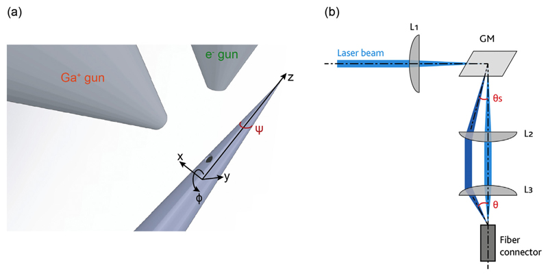
Tapered, metal-coated and patterned fibers were realized from NA = 0.39 and NA = 0.66 fibers with core/cladding diameters of 200 μm/225 μm and 200 μm/230 μm respectively, following the procedure described in detail by Sileo et al. [27]. Tapers with different taper angle ψ (see Fig. 1(a) for definition) were obtained from OptogeniX (OptogeniX s.r.l., Arnesano, Italy, www.optogenix.com). A 600 to 800 nm-thick layer of aluminum was deposited on TFs by means of thermal evaporation. Aluminum was preferred with respect to gold by virtue of its higher reflectivity at the absorption peak of ChR2. However, it is important to mention that in case of chronic employment of the aluminum-coated TFs, the taper should be encapsulated within a water proof material such as Parylene-C, in order to prevent tissue inflammation. During the evaporation process, TFs were rotated around their axis at a constant angular speed of a few rpms using a stepper motor [27]. Optical apertures were realized on the metal coating through FIB milling using a FEI Helios Nanolab 600i Dual Beam system, with ion beam currents of IFIB = 9.3 nA or IFIB = 2.5 nA (corresponding to a beam diameter of 249 nm and 133 nm, respectively), dwell time of 1 μs, and pixel pitch of 124.5 nm [25,27]. Dwell time and pixel pitch were kept constant in the realization of the different geometries, while IFIB was modified to optimize the processing time with respect to the required resolution. Simultaneous SEM imaging was performed in order to stop the milling processes as soon as the fiber surface underneath the metal layer was completely exposed. Fig. 1(a) shows a schematic representation of the SEM-FIB chamber, with a definition of a reference frame used throughout the manuscript.
Fig. 1.
(a) Schematic representation of the SEM-FIB chamber. The system is equipped with a micro-manipulator, which allows for moving the fiber along the depicted xyz-ϕ axis. Definition of the taper angle ψ is also reported. (b) Light injection system used to couple light into the fiber with a defined input angle θ. Lens L1 focuses light on the surface of the galvanometric mirror GM. GM redirects the light beam with an angle θs, and lenses L2 and L3 relay and focus the beam on the fiber core with the desired input angle θ.
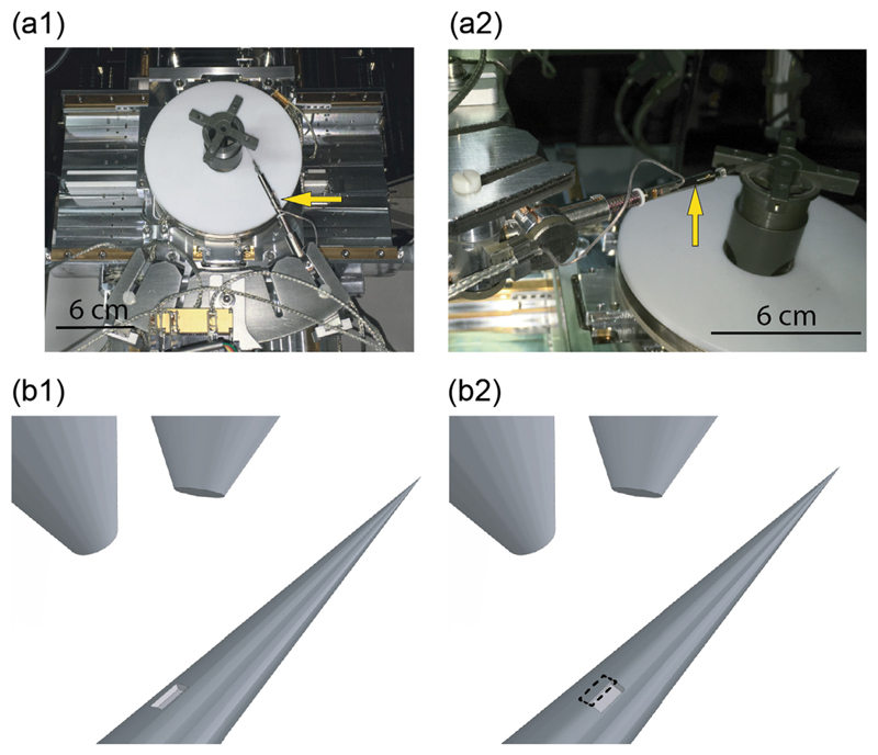
The ring-shaped window was realized using a micromanipulator (RoTip in conjunction with MM3A-EM, Kleindiek Nanotechnik GmbH) equipped with a custom holder to roto-translate the TF during the milling process. Successive millings were performed on rectangular 10 × 20 μm2 windows, overlapping for ~1 μm along the shortest side (oriented perpendicularly to the fiber axis). The fiber was rotated by 20° around its axis between subsequent processes. The eccentricity of the micromanipulation system was corrected by translating the fiber to ensure that the milling happened over the TF portion facing the ion gun at the center of the field of view and in the ion beam focal plane. Data reported in this work were obtained from: four slot-emitting TFs (of which two 0.39 fibers with 500 μm slot, one fiber with two 250 μm slots on opposite sides and one 0.66 fiber with a 1.5 mm long slot); three four-window emitting fibers fabricated from 0.66 fibers; one 0.39 fiber with a ring-shaped window.
2.2. Light injection into the fiber
For full Numerical Aperture (NA) light injection, a continuous wave (CW) diode-pumped solid state (DPSS) laser source (λ = 473 nm, Laser Quantum Ciel 473, Laser Quantum, Stockport, UK) was collimated with a 10× beam expander and focused into the fiber with an objective lens (Olympus UIS-2 Plan N 40× NA = 0.65, Olympus Corp., Tokyo, Japan). For angle-selective light injection, light was coupled into the TFs by using the optical path depicted in Fig. 1(b). The CW beam was coupled to a patch fiber through a scanning system composed by lenses L1 (focal length f1 = 100 mm, Thorlabs LA1050-A, Thorlabs Inc., Newton, New Jersey, US) and L2 (f2 = 100 mm, AL50100-A), a galvanometric mirror GM (Sutter RESSCAN-MOM), and by lens L3 (f3 = 32 mm, AL4532-A). Lens L1 focuses light on the rotation axis of the GM, while lenses L2 and L3 relay the beam deflected by the GM to the input facet of the fiber. Given a deflection θs imposed to the beam by the GM, the input angle θ into the optical fiber is given by θ = tan−1(f2 . f3−1 . tan θs). TFs were connected to the patch fibers of matching NA through a ferrule-to-ferrule butt coupling.
2.3. Light emission characterization
The tapered section of the fiber was immersed in a phosphate-buffered saline (PBS):fluorescein solution positioned in the sample plane of an epi-fluorescence upright microscope equipped with a 4× objective lens (Olympus XLFluor 4×/340). The 473 nm light emerging from the TF generated green fluorescence into the PBS:fluorescein droplet, which was collected by the objective, passed through a Fluorescein Isothiocyanate (FITC) filter and was imaged on a sCMOS (scientific grade Complementary Metal Oxide Semiconductor) sensor (Hamamatsu ORCA-Flash4.0 v2). Image acquisition was synchronized with the movement of the galvanometric mirror (Fig. 1b) using custom-written LabView software (National Instrument, Austin, Texas, US). Fluorescence intensity profiles were extracted from the acquired images along lines parallel to the taper surface.
2.4. Temperature measurement
The temperature increase of the four-window device during light delivery from each aperture was measured in air through a thermal Infra-Red (IR) camera (Testo model 875-1i, Testo Ltd. Alton, Hampshire, UK). The default calibration of the camera was adjusted for Aluminum, not oxidised (25 °C) with emissivity 0.02. The measurement in air neglects the heat dissipation provided by blood flow when the device is inserted in living animals.
For each launching condition, the taper temperature was observed at three output power densities (1 mW/mm2, 10 mW/mm2, and > 60 mW/mm2). Thermal images were acquired after 5 s of laser excitation (referred to as “laser on”) and 25 s after laser shutting (referred to as “laser off” images), to allow cooling at room temperature. Typical acquired images are displayed in Fig. S1.
3. Results
3.1. Transversal propagation constants in dielectric vs metallic tapers
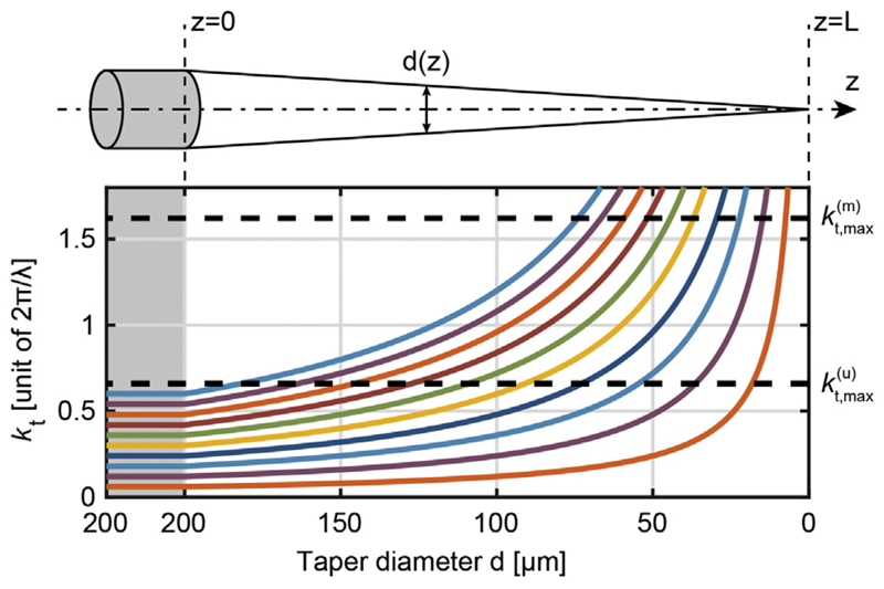
The tapered region of the optical fiber can be modeled as a narrowing waveguide along the z-axis (see axis definitions in Fig. 2), with light that is confined into the taper by means of pure dielectric or metallic confinement [10,25–27]. Light propagation in the two cases is described by different modal functions [23,24]. However, given z0 and z1 as arbitrary positions on the fiber axis in the tapered regions with z0 < z1, the effect of the diameter narrowing from d(z0) to d(z1), on propagative modes is the same: an increase of the transversal component of their transversal wave-vector, following the relationship:
| (1) |
Fig. 2.
Evolution of kt inside the taper as a function of the waveguide diameter. Several values of kt in the non-tapered region of a NA = 0.66 TF are shown (from 0.06·2π/λ to 0.60·2π/λ with steps of 0.06·2π/λ). The grey-shaded area represents a non-tapered region in which these kt values remain constant until the waveguide starts narrowing. The two dashed lines represent the bound imposed by the different confinement mechanisms for uncoated and metal-coated TFs, kt, max(u) = 0.66·2π/λ and kt, max(m) = 1.62·2π/λ, respectively.
This relation is meaningful until kt reaches an upper bound, hereafter referred to as kt, max(u) and kt, max(m) for uncoated and metalized fibers, respectively. The different boundary conditions dictated by the dielectric-dielectric and the dielectric-metal interfaces result in a noticeable mismatch between the imposed bounds in the two types of waveguides. For uncoated TFs, kt, max(u) depends exclusively on the numerical aperture (NA) of the fiber, i.e.
| (2) |
When kt, max(u) is overtaken, light is emitted in the environment surrounding the taper. For metalized tapers kt, max(m) is, instead, dictated exclusively by the refractive index n of the medium filling the waveguide, i.e.
| (3) |
modes with kt exceeding this upper bound are not leaked into the environment, but are attenuated, vanish inside the waveguide, and absorbed in the metallic coating. Considering the evolution of kt along the taper (Eq. (1)) and the different upper bounds kt, max(u) and kt, max(m) it follows that, at a given section, metallized tapers propagate modes with higher kt values with respect to uncoated tapers, as described by the kt behavior along the taper displayed in Fig. 2. If the metal coating is removed at a specific taper section, modes with a kt comprised in the range kt, max(u) < kt < kt, max(m) cannot propagate further into the taper, because the dielectric confinement condition is not fulfilled and there is no metal to confine the light. On the other hand, the modal energy is still available, since kt < kt, max(m): the only possibility is that light is coupled to the environment, thus being delivered to the surrounding medium with a consistent out-of-axis direction. Therefore, if properly patterned, the metal coating can play the double role of (i) preventing leakage of light in unwanted axial positions and (ii) structuring the illumination geometry according to the brain region of interest. In the following paragraphs examples of this application are given, with comparison between uncoated and metal-coated tapers.
3.2. Slot-emitting tapered fibers for illuminating widely extended brain regions
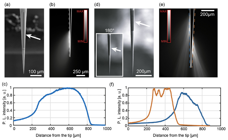
Although uncoated TFs can substantially widen the stimulated brain volume with respect to other approaches [10,11], their emission has an intrinsic 360° symmetry around the optical axis of the taper [10,11]. Breaking this symmetry will enable experiments targeting functional sub-units of well-defined brain areas, potentially leading to a 3D mapping of functional subdivisions in complex brain structures, such as the striatum [28]. Asymmetry in light emission can be obtained by patterning metal-coated TFs, so to restrict the illumination to a specific angular width around the taper axis while keeping uniform light delivery along a specific segment of the taper. This is shown in the two representative devices displayed in Fig. 3, hereafter referred to as Slotemitting TFs (Slot-TFs). Slot-TFs were realized by removing the metal over a slot aperture on an Al-coated fiber with a FIB milling process, as shown in the representative SEM micrographs for a 0.5 mm-long slot in Fig. 3(a). The ion beam current for milling was set to IFIB = 9.3 nA, resulting in process time of 45 min to mill an area of 15 μm × 500 μm. Injecting light across the full NA input of a Slot-TF produces a relatively uniform light output along the slot aperture (Fig. 3(b, c)). In terms of emitted power density, for an input power Pin ~ 1 mW the delivered light was estimated to be PDout ~ 54 ± 3 mW/mm2 (measured with the method described in ref. [22]), well above the 1 mW/mm2 well recognized as a threshold for exciting ChR2 [4].
Fig. 3.
(a) SEM micrograph of a 500 μm long slot aperture patterned on the taper surface of an Al-coated NA = 0.39 TF. (b) Fluorescence image of the light emission pattern from the Slot-TF with full NA light injection. The dashed line represents the region over which the profile in panel c was measured. Continuous white lines highlight the TF surface. (c) Normalized emission profile for a 500 μm long, 15 μm wide slot aperture patterned on a NA = 0.39 fiber. Laser light was injected within the TF full NA. (d) SEM micrographs of the dual slot TF over a NA = 0.39 Al-coated tapered fiber with taper angle ψ = 4.5°. The inset shows the opposite side of the taper. (e) Fluorescence image of the light emission pattern from the dual slot TF with full NA light injection. Dashed and continuous lines as in (b). (f) Normalized emission profiles for two ~250 μm long, 15 μm wide slot apertures patterned on opposite sides of a NA = 0.39 fiber; the orange and blue curves represent the light intensity profile on the right-hand and the left-hand sides of the fiber, respectively. (For interpretation of the references to color in this figure legend, the reader is referred to the web version of this article.)
The approach also allows the realization of slot lines at different positions around the taper circumference, provided that the fiber is appropriately rotated. An example of a dual slot TF is shown in Fig. 3(d), where two linear slots ~250 μm-long were milled on two opposite side of an Al-coated taper, with taper angle ψ = 4.5°, realized on a NA = 0.39 fiber with core/cladding diameters of 200/225 μm. When light is injected across the whole NA, out-coupling arises from both slot apertures (Fig. 3(e)), with similar light intensity profiles (Fig. 3(f)).
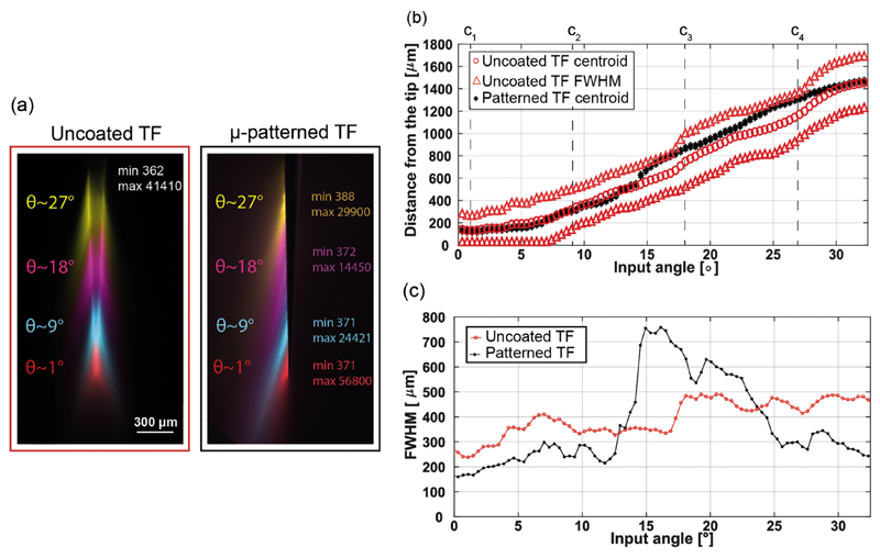
An important property of uncoated TFs that can be extended to slot-TFs is site-selective light delivery through mode-division demultiplexing. To compare this effect with the case of metallized fibers, the same measurement was performed for a NA = 0.66 Slot-TF with taper angle ψ = 4.5° and a 1.5 mm milled aperture and an uncoated TFs with similar ψ. Optical emission for different values of θ is shown in the false-color image in Fig. 4(a). The comparison between uncoated TF and Slot-TFs with angle-selective light injection shows that light is out-coupled at similar distances from tip. This is quantified in Fig. 4b, showing the position of the intensity centroid (intended as the average of the position along the taper weighted with the profile intensity) of the emission region as a function of θ. On the other hand, we observed an increase in the extent of the light emitting portion for Slot-TFs injected with angles in the range θ ∈ [12°; 22°], as quantified by the full-width-at-half-maximum measurements reported Fig. 4(c) for the two fibers. This effect was also noticed in the relative intensity of the emission profiles displayed in Fig. 3(c), where a larger spread of the input power for injection at θ ~ 18° lead to a lower number of camera counts for an approximately constant input power (860 ± 130 μW). Therefore, the θ-selective light launch can be used to dynamically select a restricted light-delivery segment along the taper with an illumination of few hundreds of micrometers.
Fig. 4.
(a) A comparison of modal de-multiplexing properties between an uncoated TF and a single slot, Al-coated TF. Modal subsets were selected by injecting laser light at increasing angles θ (1°, 9°, 18°, and 27°). Left, false color overlay of the emission profiles for an uncoated 0.66 NA TF with taper angle ψ = 4°. Minimum and maximum pixel values for all false colors are reported in white. Right, false color overlay of the emission profiles for a single slot, Al-coated NA = 0.66 TF with similar taper angle. Minimum and maximum pixel values for each false color are reported in the corresponding color. (b) Position of the intensity centroid of the emission region for an uncoated 0.66 NA TF (orange circles) and for a single-slot Al-coated NA = 0.66 TF (black stars) with respect to the light input angle. Dashed orange circles represent the position of the FWHM of the emission region for the uncoated TF. (c) FWHM of the emission profiles versus the input angle for an uncoated 0.66 NA = TF (red dots) and for a single-slot Al coated 0.66 NA TF (black dots). (For interpretation of the references to color in this figure legend, the reader is referred to the web version of this article.)
3.3. Four-window tapered fiber
Slot-TFs provide for a versatile tool to deliver light along a portion of the taper that can be dynamically selected by changing the input angle θ. However, the width of the injected modal subsets (in terms of kt intervals) and the presence of modal mixing effects [10] result in illumination patterns that cannot be restricted to less than a few hundreds of micrometers. To deliver light to smaller volumes, it is therefore necessary to realize small apertures along the taper by FIB milling, as shown in the representative SEM image of a four-window TF in Fig. 5(a). This approach has been previously demonstrated to be effective to obtain multipoint and site-selective modulation of neural activity in vivo [25]; however, it was limited to three independently addressable light emission points. This limit can be ascribed to the low numerical aperture (0.22) of the fibers used in ref. [21], which restricts the interval of available kt values to the range kt ϵ [0; 2.92 · 10−3] nm−1 at 473 nm.
Fig. 5.
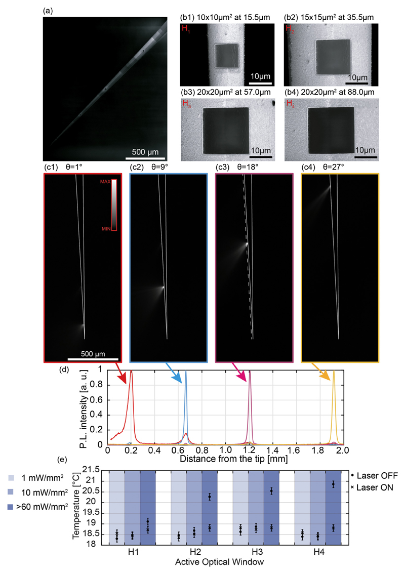
(a) SEM micrograph of a typical four-window NA = 0.66 Al-coated TF. Image contrast was modified in post-processing. (b) SEM micrographs of the four windows realized over a NA = 0.66 Al-coated TF. (b1): Window H1; (b2): window H2; (b3): window H3; (b4): window H4. (c) Fluorescence images of the light emission pattern from a four-window NA = 0.66 Al-coated TF, in correspondence of input angles θ = 1° (c1), θ = 9° (c2), θ = 18° (c3) and θ = 27° (c4). The dashed line in panel (c3) represents the region over which the light intensity profiles shown in panel (d) are collected. Continuous white lines highlight the TF surface. (d) Normalized light intensity profiles collected along the dashed line in panel (c3) for input angles θ = 1° (red curve), θ = 9° (cyan curve), θ = 18° (pink curve), and θ = 27° (yellow curve). (e) Taper temperature measured for each window (H1, H2, H3, H4), at increasing output powers (light blue column 1 mW/mm2, blue column 10 mW/mm2, dark blue column > 60 mW/mm2), for 5 s laser on (circles) and 25 s laser off (crosses) periods. Data points represent the maximum temperature recorded in a 5 × 5 pixel area surrounding the taper tip (see Fig. S1). Error bars were estimated on the base of n = 24 measurements as σt, i is the standard deviation of a 11 × 11 pixel reference area (shown in Fig. S1) in the i-th measurement, while σ〈t〉 is the standard deviation of the mean values recorded in the reference area across all measurements. (For interpretation of the references to color in this figure legend, the reader is referred to the web version of this article.)
Using NA = 0.66 TFs, instead, this set of kt is extended to kt ϵ [0; 8.77 · 10−3] nm−1; this, in turn, leads to a higher versatility on the TF design. Indeed, as shown in Fig. 4(a, b) both uncoated and slot-aperture NA = 0.66 TFs allow the identification of four input angles at which emitting portions of the taper are not overlapping (θ1 ~ 1°, θ2 ~ 9°, θ3 ~ 18°, θ4 ~ 27°): this results in four independently addressable emission regions. For these four angles, we identified the position of the emission centroid (c1, c2, c3, and c4 in Fig. 4(b)) and the related taper diameters (a1 = 15.5 μm, a2 = 35.5 μm, a3 = 55.5 μm and a4 = 88.0 μm). Four apertures (named H1–H4) on the Al coating of a NA = 0.66 TF (taper angle ψ = 3.2°) were then realized at the same taper diameters a1 to a4. The realization of each window required a process time ranging from 5 to 10 min, and it was milled by selecting an ion beam current IFIB = 9.3 nA for the two biggest windows. For patterning H1 and H2 we instead used IFIB = 2.5 nA, decreasing the beam size to better process the lower radius of curvature surface, in order to keep the beam diameter (249 nm for IFIB = 9.3 nA and 133 nm for IFIB = 2.5 nA) well below the curvature radius of the taper at which patterning is realized. A SEM micrograph of the four windows at different taper diameters is displayed in Fig. 5(b). The angle-selective light injection system was used to characterize light emission as a function of the input angle θ. Results are displayed in Fig. 5(c): input angles θ1 ~ 1°, θ2 ~ 9°, θ3 ~ 18°, and θ4 ~ 27° resulted in selective light delivery from windows H1, H2, H3 and H4, respectively. The corresponding normalized light intensity profiles, collected along the dashed line in Fig. 5(c) and depicted in Fig. 5(d), are used to assess extinction ratios between windows, defined as the intensity recorded from the single active window divided by the emission from another window. These were found to be > 6:1 in all cases. Concerning the delivered output power density from the i-th window (PDHi) at the activation angle θi, for an input power of Pin ~1 mW, we obtained PDH1 = 13.9 ± 0.8 mW/mm2, PDH2 = 3.3 ± 0.2 mW/mm2, PDH3 = 1.7 ± 0.1 mW/mm2 and PDH4 = 2.6 ± 0.2 mW/mm2 (measured with the method reported in ref. [22]). Also in this case, obtained data are above the 1 mW/mm2 ChR2 excitation threshold; in this regard, it is interesting to consider the relatively low input power. In the case of a practical use in vivo, however, it is also important to consider that to obtain the same output power density from each window Pin has to be modulated. As an example, with reference to the PDHi values mentioned above, to obtain 10 mW/mm2 from the selected window the input power should be tuned to Pin ~ 0.7 ± 0.1 mW when activating H1, Pin ~ 3.3 ± 0.1 mW when activating H2, Pin ~ 5.9 ± 0.1 mW when activating H3 and Pin ~ 3.9 ± 0.1 mW when activating H4. It is important to highlight, however, that a consistent part of the light is not emitted by the window and it keeps propagating into the taper, undergoing to the evanescence phenomenon described in Section 3.1. The resulting evanescent modes generate a current density onto the metal layer that generates thermic dissipation. We used a thermographic IR camera to evaluate the temperature reached by the taper after 5 s of light delivery from each window at three different emission power densities (1 mW/mm2, 10 mW/mm2 and > 60 mW/mm2). As a control, we have also measured the temperature of the taper 25 s after the laser is turned off, to let the taper cool down to room temperature. The recorded temperatures at the different experimental conditions are displayed in Fig. 5(e), while typical images acquired with the thermographic camera are shown in Supplementary Fig. S1. For each window, light delivery at 1 mW/mm2 and 10 mW/mm2 does not result in a significant temperature increase, with the “laser on” temperature being consistent with the “laser off” measurement (Fig. 5e, see the caption for the estimation of 0.3 °C error bars). Conversely, when the power density is increased above 60 mW/mm2, a significant temperature increase is recorded.
To estimate the repeatability of the fabrication process to realize optical windows at specific diameters (d) along the fiber taper, we have run tests on multiple devices realizing windows of different size at increasing taper diameters, namely w1 (10 μm × 10 μm window at d = 15 μm), w2 (15 μm × 15 μm window at realized at a d = 35 μm) and w3 (20 μm × 20 μm window at realized at a d = 55 μm). As a quantitative measurement of process repeatability, we have estimated activation angles θi for the wi-th window on n = 3 devices for each window, obtaining the following outcome (represented as mean ± standard deviation): θ1 = 3° ± 2°, θ2 = 10° ± 1° and θ3 = 18° ± 2°.
3.4. Ring shaped window
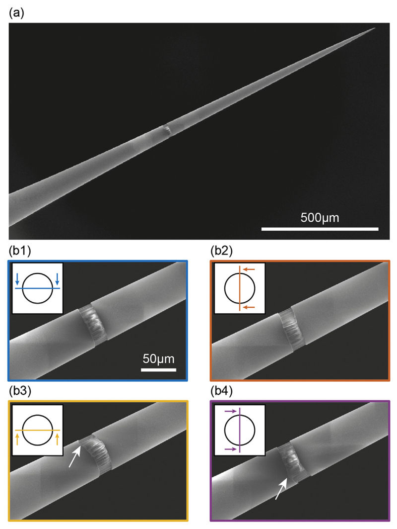
Although small square or rectangular windows confine light emission on a well-defined position along the TF axis, they prevent the experimenter from delivering light all around the TFs surface. While this is a desirable capability to address specific sections in brain regions with 360° symmetry, such as cortical columns, conventional fabrication methods make the realization of structures around a 3D-shaped surface (i.e. non-planar) cumbersome, thus limiting the possible outcomes of the process. To address this shortcoming, we implemented a method to micro-manipulate TFs into the FIB chamber using a 4-axis (xyz-ϕ) actuator (Fig. 6(a1)) and a custom ferrule holder (Fig. 6(a2)). Using this approach, we structured the TF's conical surface around the full 360° to fabricate an annular window (hereafter referred to as ring) on an Alcoated, ψ = 3.4°, NA = 0.39 TF at a diameter of 60 μm. The ring was obtained by patterning rectangular areas (10 × 20 μm2), while rotating the fiber of 20° around its axis between subsequent millings and accounting for ~1 μm overlap between adjacent areas, as shown in the representative schemes in Fig. 6(b1–b2). The obtained ring-window is shown in Fig. 7(a), and details for four rotational angles are presented in Fig. 7(b1–b4). The 10 × 20 μm2 patterns were realized using IFIB = 2.5 nA. Each rectangle required 21 min of processing time for an overall processing time of 7 h.
Fig. 6.
(a) Photographs of the micromanipulation system. The yellow arrow in panel (a1) highlights the xyz-ϕ motor, while the one in panel (a2) high-lights the tapered fiber and its holder. (b) Schematic representation of the ring fabrication process. After the realization of a first rectangular pattern (panel (b1)), the fiber is rotated around its axis by an angle of 20° and another rectangular pattern is partially overlap over the previous one (panel (b2)). (For interpretation of the references to color in this figure legend, the reader is referred to the web version of this article.)
Fig. 7.
(a) SEM micrograph of an Al-coated TF with a ring-shaped window milled on its surface. (b) Details of the window in panel (a); each subpanel shows the fiber rotated around its axis by an angle of 90° with respect to the previous subpanel. A stitching defect is evident in panel (b3–4). The legend in each panel highlights the plane of view position with respect to the TF cross section. The stitching defect has been indicated with a white arrow in panels b3 and b4.
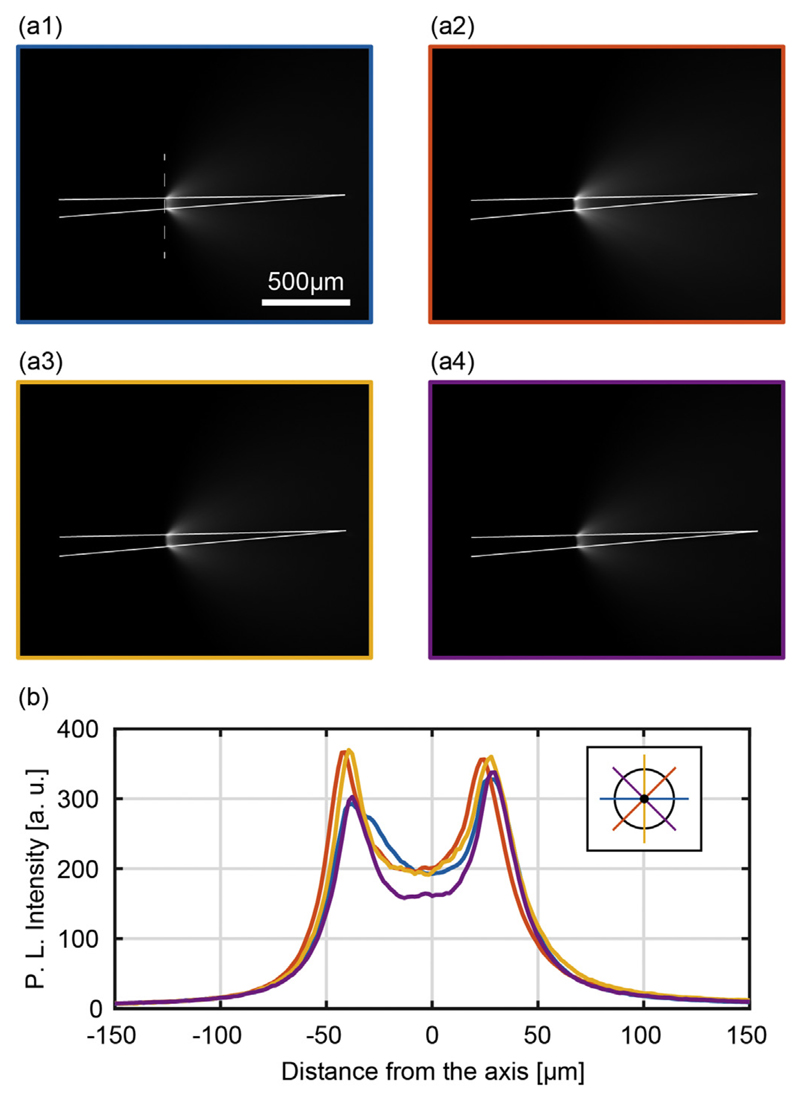
Optical emission from the ring is shown in Fig. 8(a1–a4) at four different rotational angles 0°, 45°, 90°, 135°. The similar emission profiles observed for the four positions demonstrate a good symmetry around the taper. To evaluate the difference in emitted light intensity, emission profiles were measured along the dashed lines in Fig. 8(a1–a4) and overlapped in the graph in Fig. 8(b). This resulted in a good match, with < 20% deviation between the highest and the lowest peak intensity. For input power Pin = 1 mW, the output power density from the ring-shaped aperture was measured as PDout = 4.8 ± 0.3 mW/mm2 (measured with the method used in ref. [23]).
Fig. 8.
(a) Typical fluorescence images of the light emission pattern from ring-window TF with full NA light injection, shown for four different orientations separated by 45° rotations. The dashed line in panel (a1) represents the region over which the light intensity profiles shown in panel (b) are collected. Continuous white lines highlight the TF surface. (b) Light intensity profiles collected along the dashed line in panel (a1) for the different orientations of the fiber shown in panel (a). The legend highlights the profile position with respect to the TF cross section.
4. Discussion and conclusions
4.1. Tailoring light delivery geometries with TFs
Tapered optical fibers represent a promising tool for optogenetic control of neural activity in vivo, with the main advantages of reduced invasiveness with respect to flat cleaved fibers and the possibility to dynamically change the position and size of the stimulated volume [10,11,25,26]. Flat-cleaved fibers, in fact, can only illuminate a fixed volume in the vicinity of the fiber tip. To modify the illumination region, the experimenter has to move the fiber within the brain, certainly a less-than-ideal practice. By contrast, TFs not only can address a larger volume but also provide for reconfigurable light delivery. Notably, we previously demonstrated that TFs, while maintaining the practical advantages of flat fibers, can elicit optogenetic responses with a minor amount of delivered optical power [10].
Tapered fibers optical properties are strongly linked to the waveguide's modal behavior and, in particular, to the sustained subset of transverse components of the wave vector (kt) [23]. In particular, fibers with larger NAs (here tested up to NA = 0.66) allow for a wider span in kt that, in turn, leads to longer emission lengths and higher modal demultiplexing selectivity [12].
In this work metal coating around the taper is exploited to further extend the range of available kt values and, in combination to unconventional FIB patterning, to enable the realization of complex light delivery patterns from the taper edge. Capitalizing on that, we structured the illumination geometry from metallized TFs to address one of the overarching challenges of optogenetic investigation: to harness light delivery with a tight control on the extent of the illuminated region.
To do this, we developed three novel typologies of illuminating devices based on metallized TFs: Slot-Emitting TFs (Slot-TFs), 4-window emitting TFs, and ring-window emitting TFs. Slot-TFs break the cylindrical emission symmetry of uncoated TFs and confine light delivery to a narrow slot (15 μm) that can be, potentially, of any length along the taper. As shown in Fig. 3, Slot-TFs can also be arranged to have independent slots on opposite sides of the taper surface, a design that could allow for stimulation geometries not achievable with other light-delivery systems (an example for that is shown in Supplementary Fig. S2A, where the dual-slot TF is suggested for illumination of layer 2/3 in the pre-limbic region of the prefrontal cortex and of layer 5 in the infra-limbic region). These devices also maintain the reconfigurable light delivery properties known from uncoated TFs (Fig. 4) [10,26,29], and they can potentially find application in the optogenetic dissection of neural circuits by targeting spatially confined functional units, for example in the mouse hippocampus [30]. Since slots can be realized for lengths above 1 mm, applications can be extended also to the non-human primate brain. For instance, optogenetic stimulation via uncoated TFs has been recently employed to investigate the contribution of the Frontal Eye Field (FEF) during memory-guided eye movements in primates [11]. Leveraging on the intrinsic temporal specificity of optogenetic stimulation at relatively low power densities (≤100 mW/mm2), the authors demonstrated that the FEF contributes to saccadic movements toward remembered location during every epoch of the memory-guided saccade task (namely visual stimulus presentation, delay interval and motor preparation). In light of these results, Slot-TFs could enable for an asymmetric and site-selective light delivery that would inactivate FEF sub-regions with spatio-temporal specificity. Although slot-TFs have been designed to address moderately extended brain regions (500 μm in the predominant direction), they can hardly be used when small brain volumes have to be illuminated. The versatility of FIB milling, however, allows realizing small square patterns, restricting emissions to very small surfaces (in the order of a few hundreds of μm2). By exploiting the wider set of transverse wave vector components (kt) of NA = 0.66 TFs, a 4-window device was realized to enable site-selective light delivery at four specific points arranged along 1.7 mm (Fig. 5), a configuration well matching with layered brain structures, such as the neocortex [25]. Layered organizations such as cortical columns, however, would strongly benefit by a 360° symmetric emission at specific points (as shown in representative scheme in Fig. S2B). To implement this feature, we developed a system to roto-translate the fiber during milling and to realize ring-shaped optical apertures (Fig. 6). This allowed confining the emission over a depth of 20 μm while enabling full cylindrical symmetry in the emission (Fig. 7), resulting in a new approach to FIB-processing all-around the surface of a tapered optical fiber.
An interesting comparison can be drawn between metal-coated, micro-structured TFs and probes with integrated μLEDs and recording electrodes. The main advantages offered by micro-structured TFs [25,26] can be identified as: (i) simplicity of the device, (ii) illumination of large volumes, (iii) versatility in designing tailored light-delivery geometry, (iv) multi-wavelength operation, and (v) low thermal stress at powers < 60 mW/mm2. At the same time, optrodes with recording electrodes and individually addressable μLEDs sources [9,13,15,17] outperform TFs for: (i) simultaneous stimulation and recording from multiple positions with a single probe, (ii) high-density of illuminating sites, (iii) scalability of illuminating sites and recording electrodes (iv), flexible implants, and (v) wireless implants for experiments in freely-behaving animals. The two technologies can therefore be regarded as complementary approaches for advanced optogenetic investigations of neural circuits in vivo.
Future research will focus on empowering micro-structured TFs as a tool for tailored light-delivery in experiments targeting anatomically diversified brain regions. To this end, we envision that the novel devices described in this work can be combined with recording electrodes as we demonstrated in a previous work [25]. This was done by positioning the structured fiber beside a linear array of recordings electrodes with optical windows oriented toward the recording pads. The novel light-delivery geometries we propose will provide researchers with tailored light delivery to better interface with anatomically diversified brain regions.
4.2. Drawbacks
An important drawback of the FIB milling applied to TFs lies in the complex and time-consuming processes to realize apertures on wide surfaces. In particular, realizing structures that extend beyond the field of view (FOV) requires a precise alignment of multiple milling patterns. For instance, let us consider the representative case of a 1500 × 10 μm2 slot aperture to be realized along the taper. Taking into account the ~1000 × 700 μm2 available FOV, it is reasonable to split the process in two millings, each patterning an aperture of 750 × 10 μm2. Since the FOV is discretized in a digital image of 1536 × 1024 pixels (each pixel being 0.65 × 0.68μm2), the first slot will be visualized on ~1154 × 15 pixels. The second pattern (also 750 × 10 μm2) should then be aligned to the shorter edge of the first one. However, the short edge is visualized in only 15 pixels. An alignment error of 2 pixels between the two patterns, for example, results in a shift of 1.36 μm that represents the 14% of the short-edge length. These imperfections might result in slight variation on the uniformity of the light emitted in the patterned area, although they could be reduced by splitting the process in multiple smaller patterns to work on smaller FOV, with the downside of increasing the overall fabrication time. Alignment between subsequent milling patterns resulted in fabrication defects also for the ring-shaped apertures, with stitching misalignments clearly visible in Fig. 7(a–b1–b4).
Additionally, when the fiber is rotated on its axis, the eccentricity induced by the fiber mount should be taken into account. In the process for realizing the ring aperture discussed in Section 3.4, this resulted in a slight misalignment between the first and the last rectangular patterns. The presence of this asymmetric rotation arises from a misalignment between the rotational axis of the stepper motor and the taper axis, as shown in Supplementary Fig. S3. Indeed, before being installed in the FIB chamber, the TF is connectorized with a standard ferrule. The ferrule has two apertures: one with a diameter of ~230 μm and the second of 0.6 mm. The non-tapered part of the fiber is accommodated in the 230 μm aperture. This aperture is slightly bigger than the core/cladding diameter (225 μm) and can shift the fiber axis with respect to the ferrule axis of 5 μm. Additionally, the tapered region exits from the 0.6 mm aperture and might bend during the time required by the glue to dry. If the 5 μm axial misalignment is a systematic error, the fiber bending can hardly be quantified and it is evaluated and corrected case-by-case. To realize the ring-shaped window, we compensated for this asymmetry by manually adjusting the fiber position at each fabrication step and by modifying the shape of the last pattern in order to close the ring (as shown in Fig. 7(b4)). To this end, an automatized procedure can be envisioned by exploiting live imaging with the SEM column to quantify the eccentricity and automatically correct the taper position during process.
Supplementary Material
Supplementary data to this article can be found online at https://doi.org/10.1016/j.mee.2018.03.023.
Acknowledgments
F. Pisanello and F. Pisano acknowledge funding from the European Research Council under the European Union's Horizon 2020 research and innovation program (#677683); M.P. and M.D.V. acknowledge funding from the European Research Council under the European Union's Horizon 2020 research and innovation program (#692943). L.S., A.Q., M.D.V. and B.L.S. are funded by the US National Institutes of Health (U01NS094190); B.L.S. is funded by the Simons Collaboration on the Global Brain (#543037SPI).
References
- [1].Deisseroth K. Optogenetics: 10 years of microbial opsins in neuroscience. Nat Neurosci. 2015;18:1213–1225. doi: 10.1038/nn.4091. [DOI] [PMC free article] [PubMed] [Google Scholar]
- [2].Häusser M. Optogenetics: the age of light. Nat Methods. 2014;11:1012–1014. doi: 10.1038/nmeth.3111. [DOI] [PubMed] [Google Scholar]
- [3].Boyden ES, Zhang F, Bamberg E, Nagel G, Deisseroth K. Millisecond-timescale, genetically targeted optical control of neural activity. Nat Neurosci. 2005;8:1263–1268. doi: 10.1038/nn1525. [DOI] [PubMed] [Google Scholar]
- [4].Yizhar O, Fenno LE, Davidson TJ, Mogri M, Deisseroth K. Optogenetics in neural systems. Neuron. 2011;71:9–34. doi: 10.1016/j.neuron.2011.06.004. [DOI] [PubMed] [Google Scholar]
- [5].Packer AM, Roska B, Häusser M. Targeting neurons and photons for optogenetics. Nat Neurosci. 2013;16:805–815. doi: 10.1038/nn.3427. [DOI] [PMC free article] [PubMed] [Google Scholar]
- [6].Emiliani V, Cohen AE, Deisseroth K, Hausser M. All-optical interrogation of neural circuits. J Neurosci. 2015;35:13917–13926. doi: 10.1523/JNEUROSCI.2916-15.2015. [DOI] [PMC free article] [PubMed] [Google Scholar]
- [7].Deisseroth V, et al. Next-generation optical technologies for illuminating genetically targeted brain circuits. J Neurosci. 2006;26:10380–10386. doi: 10.1523/JNEUROSCI.3863-06.2006. [DOI] [PMC free article] [PubMed] [Google Scholar]
- [8].Canales A, et al. Multifunctional fibers for simultaneous optical, electrical and chemical interrogation of neural circuits in vivo. Nat Biotechnol. 2015;33:277–284. doi: 10.1038/nbt.3093. [DOI] [PubMed] [Google Scholar]
- [9].Park SI, et al. Soft, stretchable, fully implantable miniaturized optoelectronic systems for wireless optogenetics. Nat Biotechnol. 2015;33:1280–1286. doi: 10.1038/nbt.3415. [DOI] [PMC free article] [PubMed] [Google Scholar]
- [10].Pisanello F, et al. Dynamic illumination of spatially restricted or large brain volumes via a single tapered optical fiber. Nat Neurosci. 2017 doi: 10.1038/nn.4591. [DOI] [PMC free article] [PubMed] [Google Scholar]
- [11].Acker L, Pino EN, Boyden ES, Desimone R. FEF inactivation with improved optogenetic methods. Proc Natl Acad Sci. 2016;113:E7297–E7306. doi: 10.1073/pnas.1610784113. [DOI] [PMC free article] [PubMed] [Google Scholar]
- [12].Pisanello M, et al. Tailoring light delivery for optogenetics by modal demultiplexing in tapered optical fibers. Sci Rep. 2018;8:4467. doi: 10.1038/s41598-018-22790-z. [DOI] [PMC free article] [PubMed] [Google Scholar]
- [13].Wu F, et al. Monolithically integrated μLEDs on silicon neural probes for high-resolution optogenetic studies in behaving animals. Neuron. 2015;88:1136–1148. doi: 10.1016/j.neuron.2015.10.032. [DOI] [PMC free article] [PubMed] [Google Scholar]
- [14].McAlinden N, Gu E, Dawson MD, Sakata S, Mathieson K. Optogenetic Activation of Neocortical Neurons In Vivo With a Sapphire-based Micro-scale LED Probe. 2015:25. doi: 10.3389/fncir.2015.00025. [DOI] [PMC free article] [PubMed] [Google Scholar]
- [15].Scharf R, et al. Depth-specific optogenetic control in vivo with a scalable, high-density μLED neural probe. Sci Rep. 2016;6 doi: 10.1038/srep28381. [DOI] [PMC free article] [PubMed] [Google Scholar]
- [16].McAlinden N, et al. Thermal and optical characterization of micro-LED probes for in vivo optogenetic neural stimulation. Opt Lett. 2013;38:992. doi: 10.1364/OL.38.000992. [DOI] [PubMed] [Google Scholar]
- [17].Ayub S, Schwaerzle M, Paul O, Ruther P. An intracerebral probe with integrated 10 × 1 μLED array for optogenetic experiments at 460 nm. Procedia Eng. 2015;120:472–475. [Google Scholar]
- [18].Montgomery KL, et al. Wirelessly powered, fully internal optogenetics for brain, spinal and peripheral circuits in mice. Nat Methods. 2015;12:969–974. doi: 10.1038/nmeth.3536. [DOI] [PMC free article] [PubMed] [Google Scholar]
- [19].Shin G, et al. Flexible near-field wireless optoelectronics as subdermal implants for broad applications in optogenetics. Neuron. 2017;93:509–521.e3. doi: 10.1016/j.neuron.2016.12.031. [DOI] [PMC free article] [PubMed] [Google Scholar]
- [20].Jeong J-W, et al. Wireless optofluidic systems for programmable in vivo pharmacology and optogenetics. Cell. 2015;162:662–674. doi: 10.1016/j.cell.2015.06.058. [DOI] [PMC free article] [PubMed] [Google Scholar]
- [21].Prakash R, et al. Two-photon optogenetic toolbox for fast inhibition, excitation and bistable modulation. Nat Methods. 2012;9:1171–1179. doi: 10.1038/nmeth.2215. [DOI] [PMC free article] [PubMed] [Google Scholar]
- [22].Rickgauer JP, Deisseroth K, Tank DW. Simultaneous cellular-resolution optical perturbation and imaging of place cell firing fields. Nat Neurosci. 2014;17:1816–1824. doi: 10.1038/nn.3866. [DOI] [PMC free article] [PubMed] [Google Scholar]
- [23].Snyder AW, Love J. Optical Waveguide Theory. Springer Science & Business Media; 2012. [Google Scholar]
- [24].Collin RE. Foundations for Microwave Engineering. McGraw-Hill; 1992. [Google Scholar]
- [25].Pisanello F, et al. Multipoint-emitting optical fibers for spatially addressable in vivo optogenetics. Neuron. 2014;82:1245–1254. doi: 10.1016/j.neuron.2014.04.041. [DOI] [PMC free article] [PubMed] [Google Scholar]
- [26].Pisanello M, et al. Modal demultiplexing properties of tapered and nanostructured optical fibers for in vivo optogenetic control of neural activity. Biomed Opt Express. 2015;6:4014. doi: 10.1364/BOE.6.004014. [DOI] [PMC free article] [PubMed] [Google Scholar]
- [27].Pisanello F, Sileo L, Pisanello M, De Vittorio M, editors; Hirschberg H, et al., editors. Fabrication of Multipoint Light Emitting Optical fibers for Optogenetics. 2015. 93052O. [DOI] [Google Scholar]
- [28].Hunnicutt BJ, et al. A comprehensive excitatory input map of the striatum reveals novel functional organization. elife. 2016;5 doi: 10.7554/eLife.19103. [DOI] [PMC free article] [PubMed] [Google Scholar]
- [29].Novotny L, Hecht B. Principles of Nano-optics. Cambridge University Press; 2012. [Google Scholar]
- [30].Liu X, et al. Optogenetic stimulation of a hippocampal engram activates fear memory recall. Nature. 2012 doi: 10.1038/nature11028. [DOI] [PMC free article] [PubMed] [Google Scholar]
Associated Data
This section collects any data citations, data availability statements, or supplementary materials included in this article.


