Abstract
An alternative pedicle trajectory for use at the superior end of a construct to limit dissection of the mobile superior facet joint and reduce incision length and muscle dissection, thus minimizing approach‐related trauma during pedicle fixation, is reported. The medio‐latero‐superior trajectory technique involves a starting point on the medial aspect of the pars and angulation of the pedicle screw in a mediolateral and caudocranial direction. This approach takes advantage of a predominantly cortical trajectory to assist with bone fixation. Drawbacks of this new screw trajectory are discussed along with its potential benefits.
Keywords: Lumbar fusion, Medio‐latero‐superior trajectory, Minimally invasive
Introduction
There are many techniques available for fixation, stabilization and fusion of the lumbar spine. Interbody or posterolateral bone grafting techniques are usually supplemented with solid mechanical bone fixation. The many other forms of fixation include spinous process fixation, facet screw fixation, wiring methods and well established techniques such as pedicle screw fixation. Pedicle screw techniques have been the mainstay of stabilization of the lumbar spine for decades because they provide superior mechanical fixation.
Pedicle screw insertion techniques have some drawbacks, including potential neurovascular injury and a requirement for significant muscle dissection to reveal bone landmarks for safe insertion of the pedicle screw. The standard angulation of a pedicle screw requires a lateral to medial approach and therefore, especially for caudal lumbar and sacral pedicle fixation, wide muscular dissection. Percutaneous pedicle screw techniques have been well documented for a variety of indications1, however decompression and bone graft insertion requires an additional approach which can be midline, paramedian, lateral or anterior.
We have used an alternative approach trajectory for pedicle screw insertion for trauma applications for over 10 years2 and, over time, adapted this technique to degenerative pathologies3. Advantages of this alternative pedicle trajectory include that it uses the superior end of the construct to avoid wide dissection of the mobile superior facet joint and it reduces incision length and muscle dissection, thus minimizing approach‐related trauma. The medio‐latero‐superior trajectory (MLST) technique involves a starting point on the medial aspect of the pars with angulation of the pedicle screw in a mediolateral and caudocranial direction. We here discuss both drawbacks of this new screw trajectory along with its potential benefits.
We accept that the indications for this technique are limited. The primary indication is single level degenerative fusion because the technique is not suitable for long segment pathologies such as scoliosis or kyphosis.
Technique
We have used the MLST technique for over 10 years, initially for spinal trauma cases in an attempt to avoid dissection of the superior mobile facet joint. Over time, we have adapted the technique to degenerative pathologies in an attempt to reduce incision length and facet joint trauma.
The sequence of procedure:
For safe insertion of the MLST screw, we recommend using image intensification (II) during all steps. The II should be sterile to permit obtaining lateral images at any stage during the procedure. We do not routinely use CT neuro‐navigation; however this would be an option if available.
See Figures 1A, 2. The initial starting point is medial on the pars. The surgeon needs to remove the inferior ½ of the spinous process to achieve the appropriate angulation for the trajectory. A lateral II image (Fig. 1B) should be taken to confirm the correct angulation. We prefer to perform this step with a 2 mm high speed round burr drill and not a pedicle probe due to risk of fracture of the pars.
The surgeon advances the drill (Fig. 2, part 2 and 3) using regular II imaging, making sure not to breach the superior endplate and using a “pedicle feeler” to check the lateral placement of the hole if desired. It is common for the feeler to breach the lateral aspect of the vertebral body wall; this is not a concern as it is highly unlikely to cause any neurovascular injury.
Following completion of the pedicle trajectory, the surgeon must tap the hole to the size of the planned screw. For example, the surgeon taps the hole to 4.5 or 5.0 mm if planning to use a 5.0 mm screw. Under‐tapping can result in fracture of the pars when the surgeon attempts to insert a large screw into an undersized cortical bone hole.
If a pars fracture occurs, we recommend lengthening the incision and placing a pedicle screw via a “standard” trajectory.
The surgeon should advance the MLST pedicle screw slowly with the use of several II images to confirm its accurate placement (Figs. 2, 3).
The surgeon should be careful not to breach the superior endplate, which can result in damage to the disc. However, if the screw penetrates the lateral wall of the vertebral body this is unlikely to cause any neuro‐vascular injury. Checking II images during the procedure reduces this risk.
A standard screw diameter for a lumbar MLST pedicle screw is either 5.0 or 5.5 mm, with a length of 30–35 mm. We use the Stryker (Kalamazoo, MI, USA) 4.5 mm system because of its smaller rod diameter and the pedicle screw tulip's smaller head size.
The position of the tulip of the inferior pedicle screw determines rod placement. If the surgeon has placed the inferior screw via a “standard” approach (Fig. 1A), then the rod will lie in an oblique rather than a parallel position. Rod placement may be problematic, however with a single level construct and the use of poly‐axial screws, it should not be too difficult.
Surgeons can complete the operation according to their own preferences. Bone grafting options include graft placement over the facet joints and a transforaminal lumbar interbody fusion (TLIF)/posterior lumbar interbody fusion (PLIF) approach depending upon the indications and surgeons' preferences for grafting techniques.
We recommend a postoperative CT (Figs 4, 5) to check that the MLST screw is within the confines of the pedicle.
Figure 1.
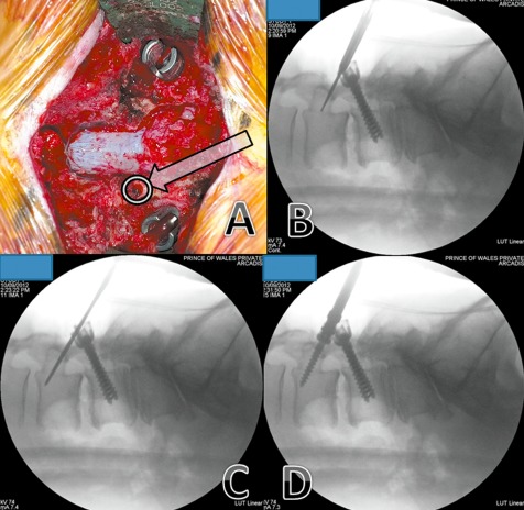
L3–4 instrumented posterolateral fusion—previous L4‐S1 onlay fusion performed 12 years ago. (A) The starting point (arrow) is at the pars interarticularis, inferior to the mobile cranial facet joint. (B) Image intensifier image showing it use for directing the drill in the planned trajectory. (C) Image intensifier image showing that, because most of the of bone traversed in this technique is cortical bone, the hole is tapped up to the planned screw diameter. (D) Image intensifier image showing insertion of screw.
Figure 2.
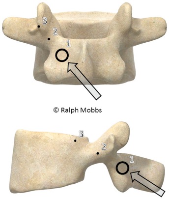
Model showing the starting point for the MLST technique (point 1). Points 2 and 3 demonstrate the trajectories that the surgeon can use during lateral or AP radiography.
Figure 3.
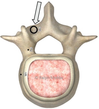
Model showing the axial trajectory for the MLST screw (arrow). The screw follows a medial to lateral path, thus avoiding lateral dissection of the paraspinal musculature.
Figure 4.
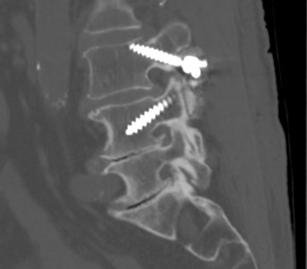
Lateral radiograph showing the trajectory of an MLST screw in L3, starting at the pars with the screw angled towards the lateral aspect of the endplate. Note the L4 pedicle screw is angled in a superior‐inferior direction, the opposite of the MLST screw.
Figure 5.
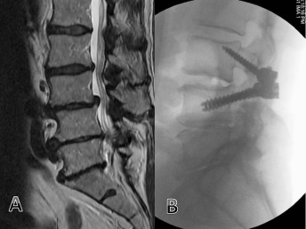
(A) MRI demonstrating L3,4 low grade spondylolisthesis and canal stenosis. (B) Fusion L3,4 with MLST technique.
Discussion
The MLST pedicle screw technique provides an alternative fixation technique that is relatively easy to perform and reduces surgical trauma at the superior aspect of the surgical exposure, thus minimizing iatrogenic facet joint injury. We have used the technique for a variety of pathologies including trauma2, tumor and degenerative conditions. However, the technique is most likely to be useful for treating single level degenerative pathologies in combination with midline insertion of an interbody graft, such as in the TLIF or PLIF technique.
Studies have demonstrated that the pullout and toggle characteristics of this alternative cortical trajectory are equivalent to those of traditional trajectory pedicle screws4, 5. Cortical trajectory screws have a 30% increase in uniaxial yield pullout load relative to traditional pedicle screws; however, mixed loading demonstrated equivalency between the two trajectories. According to both biomechanical tests and differences in failure moments, there is no significant difference in construct rigidity between the two screw trajectories. Bone quality (determined by dual‐energy X‐ray absorptiometry) does not appear to determine adequacy of pedicle screw fixation; however, there are positive correlations between trajectory and bone density scans and pullout force for both pedicle screws.
Drawbacks of this technique include difficult rod placement because the heads of the pedicle screws may not line‐up in the sagittal plane. In addition, if the patient requires revision of the construct in a cranial direction, it may be difficult to “line up the rods” because the heads of the pedicle screws may lie in various planes. The risk of this occurring depends on the surgeon's ability to position the next superior pedicle screw in the same para‐sagittal plane as the previous one.
In summary, we do not recommend this alternative trajectory for widespread use in pedicle fixation; however, it provides the surgeon with additional options for fixation depending on the indication, pathology or unique anatomy of the patient.
Disclosure: No financial support was obtained for this work.
References
- 1. Mobbs RJ, Sivabalan P, Li J. Technique, challenges and indications for percutaneous pedicle screw fixation. J Clin Neurosci, 2011, 18: 741–749. [DOI] [PubMed] [Google Scholar]
- 2. Mobbs RJ, Steel TR, Fairhall JM. Monosegmental pedicle screw fixation for thoraco‐lumbar burst fracture. J Bone Joint Surg Br, 2004, 86 (Suppl IV): S458. [Google Scholar]
- 3. Mobbs RJ, Sivabalan P, Li J. Minimally invasive surgery compared to open spinal fusion for the treatment of degenerative lumbar spine pathologies. J Clin Neurosci, 2012, 19: 829–835. [DOI] [PubMed] [Google Scholar]
- 4. Inceoğlu S, Montgomery WH Jr, St Clair S, McLain RF. Pedicle screw insertion angle and pullout strength: comparison of 2 proposed strategies. J Neurosurg Spine, 2011, 14: 670–676. [DOI] [PubMed] [Google Scholar]
- 5. Santoni BG, Hynes RA, McGilvray KC, et al Cortical bone trajectory for lumbar pedicle screws. Spine J, 2009, 9: 366–373. [DOI] [PubMed] [Google Scholar]


