Abstract
Objective: To conduct a biomechanical study of the whole reconstructed pelvic ring using a modular hemipelvic endoprosthesis.
Methods: A subject‐specific finite‐element (FE) model of the whole pelvic ring, including the pelvis, sacrum and main ligaments, was constructed. Type II+III pelvic resection was simulated on the FE model. Then a three‐dimensional model of a reconstructed pelvic ring with a modular hemipelvic endoprosthesis was developed, and FE analysis performed to compare the stresses along the bilateral arcuate lines of the reconstructed and normal pelvis in the bipedal standing position. Comparison between bilateral stress distributions along the sciatic notch was also performed. The characteristics of load transmission within the endoprosthesis were also studied.
Results: No significant difference in the stresses along the bilateral arcuate lines was observed between the reconstructed and normal pelvis. The stress distribution on the prosthesis along the sciatic notch paths was significantly greater than that on the unaffected side in the same position. The peak stress of the implant on the S1 vertebral body was 182.9 MPa under a load of 600N. Study of load transfer on the implant showed that the posterior side of the column between the point of iliac fixation and the acetabulum was subject to the greatest stress.
Conclusion: This FE study showed that a modular hemipelvic endoprosthesis can restore load transfer between the sacrum and acetabulum on simple standing. Future implant design should aim to decrease the stress concentration and make the biomechanical performance more balanced.
Keywords: Biomechanics, Bone remodeling, Finite element analysis, Prostheses and implants
Introduction
Resection and reconstruction for pelvic tumor is a particular challenge for orthopaedists, especially in regard to choosing the appropriate reconstruction method 1 , 2 . The high rates of infection and other complications after allograft reconstructions, and the desire for better functional results, have lead to the development and widespread use of endoprosthetic reconstruction methods 3 . Many different techniques of endoprosthetic reconstruction have been reported, including the saddle, custom‐made and modular pelvic prostheses, and the Schoellner pedestal cup 1 , 2 , 4 , 5 , 6 . The modular hemipelvic endoprosthesis has been reported to have a satisfactory early clinical outcome 6 . However, pelvic prostheses are products that still lack adequate design solutions. A better understanding of the mechanics for pelvic reconstruction could lead to an improved implant design and decreased mechanical complication rates.
It is difficult to assess the stress or strain distribution throughout the entire reconstructed pelvis using simplified mathematical models, implanted prostheses, or via experiments with cadaveric tissue. An alternative approach to the analysis of pelvic mechanics is the finite element (FE) method, which can accommodate large intersubject variations in bone geometry, material properties and major ligaments. Nowadays, FE method technology is mature enough to allow the creation of subject‐specific finite element models based on computed tomography data 7 .
The goal of this study was to develop a subject‐specific FE model of an entire pelvic ring including the pelvis, sacrum and major ligaments. The present authors speculated that the modular hemipelvic endoprosthesis could restore force transmission and weight bearing along the anatomic axes in the bipedal standing position, and aimed to confirm this by determining the characteristics of stress distribution along the arcuate lines and sciatic notch paths. They further wanted to investigate the characteristics of load transmission within the endoprosthesis.
Materials and methods
A 40‐year‐old female cadaveric entire pelvic ring (weight 50 kg, height 164 cm) was selected. The anatomical and X‐ray appearance of the pelvis was normal, with no evidence of deformities. The specimen was first immersed in water and then CT scanned to prevent beam‐hardening artifacts 8 .
The procedure of 3D model reconstruction adopted can be summarized in the following three steps: (i) extraction of the three‐dimensional bone surface; (ii) generation of the finite element mesh; and (iii) mapping of the materials for each element based on voxel Hounsfield units9. The image data was imported into Mimics version 12.0 (Materialise, Leuven, Belgium) for editing and model reconstruction. To complete isolation of the hard tissue, the region growing function was used. Because the left pelvis, right pelvis and sacrum are not connected, multiple regions growing were applied using different masks and colors (Fig. 1). Because of the thresholding function, some of the cancellous bone was not included. Filling of the voids was accomplished by using several editing techniques including cavity fill, draw, and local thresholding. Each mask was then converted into a 3D surface model. Then a volumetric four‐node liner solid tetrahedral mesh was created from the final surface triangle element using Abaqus 6.7 (Simulia, Providence, RI, USA). The number of elements and nodes of the models were recorded (Table 1). Inhomogeneous material properties were automatically mapped onto the FE model by the Mimics using the relations ρCa = 0.0008Hu‐0.8037, ρCa = 0.626ρapp, E = 2017.3ρapp2.46, Poisson's ratio = 0.3 3 , 10 , 11 , 12 . Major ligaments were simulated by spring elements in Abaqus to complete the pelvic ring 3D model development based on the study of Phillips et al. 13 (Fig. 2).
Figure 1.
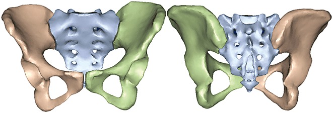
Initial 3D computer surface model of the pelvis and sacrum using Mimics.
Table 1.
Number of nodes and elements of the finite element meshes
| Model type | Parameter | Left pelvis | Right pelvis | Sacrum |
|---|---|---|---|---|
| Surface Model | Elements | 7 402 | 7 248 | 8 854 |
| Nodes | 3 703 | 3 624 | 4 387 | |
| Solid Model | Elements | 25 291 | 25 051 | 32 909 |
| Nodes | 6 186 | 6 186 | 7 871 | |
| Volume(mm3) | 303 757 | 275 393 | 183 901 |
Figure 2.
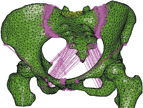
A volumetric four‐node liner solid tetrahedral mesh of the pelvic ring was established. Main ligaments were simulated by spring elements in Abaqus.
Boolean operations were used to simulate Type II+III resection of the left pelvis (Enneking classification system 4) in the 3D pelvic model. The computer aided design files of the modular hemipelvic endoprosthesis were provided by the manufacturer. The solid model of the prostheses consisted of an artificial acetabulum with 11 537 elements, iliac fixation base of 21 339 elements and pubic connection elements and single screw of 11 727 elements. The defects caused by the drilled holes created in the pelvis by the operative procedures were subtracted from the bone. Then the surface mesh of the iliac resection surface, screw holes and iliac surface adjacent to the holes were remeshed (Fig. 3). The defect in the left pelvis was remeshed with new volumetric elements of 41 415. The screw holes were created in the bone by Boolean operations which corresponded exactly to the screws used in real surgery. The exact position of the prosthesis was verified using the Mimic simulation function. For the prosthesis, the material properties of titanium alloy (TiAl6V4) were employed. The Young's modulus was set to 110 GPa and the Poisson's ratio to 0.3 14 . Contact between the implant and bone was modeled using a surface‐to‐surface algorithm. The rough coefficients of friction used were µ= 0.3 for contact between screws and bone structures, while the interface between different prosthetic parts was considered bounded 15 . A simple vertical load of 600N on the S1 vertebra was simulated without consideration of the muscular forces.
Figure 3.
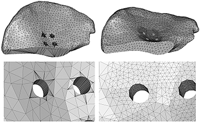
Remeshing after simulation of iliac resection and screw holes.
In order to determine whether the modular hemipelvic prosthesis could restore force transmission and weight bearing along the anatomic axes in the bipedal standing position, paths along the bilateral arcuate line and sciatic notch were made on the reconstructed FE model. Von Mises stresses were identified at nodes belonging to the paths and compared with those of the normal pelvic FE model. The load transmission part of the implant was also analyzed. The von Mises stresses distributed on the anterior, posterior and lateral sides of the implant load transfer structure were recorded.
Statistical analysis
The difference between stress levels on the arcuate lines in the two models and stress along both sciatic notch paths was tested for significance by the paired‐samples t‐test (SPSS, V16.0, SPSS, Chicago, IL, USA).
Results
All FE analysis plots were done at the same stress scale level and all stresses plotted were von Mises. Figure 4 shows the results of the von Mises plot on the reconstructed pelvis. No significant difference was observed in the von Mises stresses along the bilateral arcuate lines between the reconstructed pelvic model and normal pelvic FE model with the current load configuration (t= 0.18 P= 0.75) (Fig. 5A). The stress distribution on the prosthesis along the sciatic notch paths in the simple standing position was significantly greater on the affected side than on the contralateral side (t= 0.03 P= 0.02) (Fig. 5B).
Figure 4.
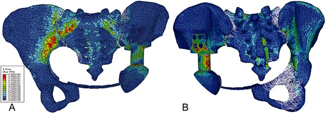
(A) Anterior and (B) posterior view of von Mises stress distribution on the reconstructed pelvis subject to a load of 600N on the S1 vertebral body.
Figure 5.
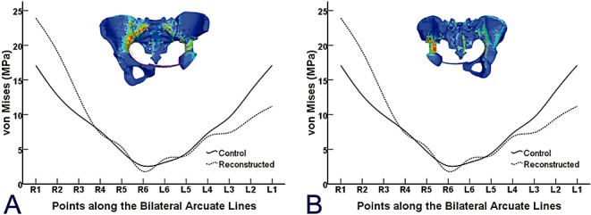
(A) Six points were chosen from both sides of the arcuate line. The solid line represents the von Mises stress of points in an intact pelvic ring, and the dashed line represents the reconstructed entire pelvic ring with illustration on the top. (B) Comparison of von Mises stress distribution along the posterior side of the implant (dashed line), which was in almost the same position as the implant sciatic notch and unaffected sciatic notch (solid line).
The peak stress on the implant was 182.9 MPa under the loading configuration of 600N on the S1 vertebral body. The stress concentration at the point of iliac fixation was at the conjunction between the lateral wing and the base. Von Mises stresses at the anterior, posterior, medial and lateral sides of the load transfer structure are depicted in Figure 6. The stress distribution was inhomogeneous, that is, the highest stress was observed on the posterior side, followed by the lateral side, especially in the proximal part and the anterior, medial side.
Figure 6.
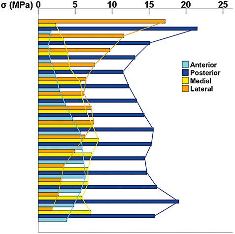
Von Mises stress distribution on the surface of the medial, lateral, anterior and posterior sides of the load transfer structure (the column‐shaped part between the point of iliac fixation and the artificial acetabulum). The greatest stress was observed on the posterior side, followed by the lateral side, especially in the proximal part and the anterior, medial side.
Discussion
The modular hemipelvic endoprosthesis has been reported to have a satisfactory early clinical outcome 6 . However, prostheses used for pelvic defect reconstruction are products that still lack adequate design solutions. A better understanding of the mechanics of the entire reconstructed pelvic ring could lead to improved implant design, decreased mechanical complication rates, improved surgical approaches, and a suitable framework for preoperative surgical planning. It is difficult to assess the stress or strain distribution throughout the entire reconstructed pelvis using simplified mathematical models or via experiments on cadavers. Therefore, a subject‐specific FE model of the entire pelvic ring, including the major ligaments, was developed.
Based on FE methodology, a numerical model was developed to study the biomechanics of a pelvis reconstructed with the modular hemipelvic endoprosthesis. Homogeneous, isotropic and linear elastic material properties are most commonly used in FE models 9 , 14 , 15 , 16 . Although FE prediction of cortical strains is not statistically different from the subject‐specific model when an average cortical thickness is used, when constant cortical bone thickness and trabecular bone elastic modulus are used, the model is significantly more rigid than the subject‐specific model 7 . Subject‐specific FE analysis of the skeleton is a very powerful tool for biomechanical research, and has been adopted in clinical applications 9 , 11 , 16 . The commonest way of constructing subject‐specific models is by deriving information from CT images. Information on the mechanical properties of bones can be derived from CT data, using a mathematical relationship between CT values and the mechanical properties of the bone 9 , 17 . The advantage of the entire pelvic ring model with major ligaments is that it has the potential to enable study of the mechanical performance of the whole pelvis when subject to complex physiological loading configurations like the gait cycle. Also, because the FE model is capable of comparing various bone defects and different reconstructions, the choice of a particular reconstruction method for a specific defect can be based on quantifiable mechanical simulations.
FE study of the reconstructed pelvis showed that the modular hemipelvic endoprosthesis can restore load transmission between the sacrum and acetabulum, although the stress distribution was not exactly the same as the physiological conditions reported by Dalstra 18 . No significant difference between reconstructed pelvis and physiological condition was observed for von Mises stresses along the bilateral arcuate lines. The anterior pelvic girdle was assess as restored with the current implant design, although slightly greater stress was found near the sacroiliac joint on the unaffected side, and a relatively lesser stress distribution was observed on the anterior surface of the prosthesis. This may indicate that stress shielding occurs on the medial and lateral sides of the reconstructed hemipelvis. This was confirmed by study of the characteristics of stress distribution along the bilateral sciatic notch paths.
The greatest stress level was found on the posterior side of the load transfer structure in the prosthesis. This stress concentration may be accompanied by stress shielding on the medial side. Also, study of the load transfer on the implant showed that the posterior side of the column between the iliac fixation part and acetabulum had the greatest stress value. Future implant design could be optimized towards meeting the mechanical demands of load transmission in the endoprosthesis.
Some limitations of the present work must be considered when evaluating the results presented here. The major limitation was that the current FE numerical model was not validated by mechanical experiments. Verification and validation is important in extracting clinically relevant data from FE simulations 19 . However, the errors of prediction of a FE model may be decreased when the model is used to compare stresses under different conditions. Some other limitations also need to be noted. First, for the pelvis, no muscle loading was used in this study. Muscular forces would definitely affect the biomechanical response of the system, because the inclusion of these forces has been found to decrease the occurrence of stress concentration within the cortex13. However, this would have no influence on the comparisons. Second, because only a simple standing load configuration was investigated in this study, the stress response of the implant cannot reflect biomechanical characteristics in daily activities, such as climbing stairs, walking and standing up from a chair. These might need further evaluation.
In summary, this FE study of the reconstructed pelvis showed that the modular hemipelvic endoprosthesis can restore load transfer between the sacrum and acetabulum. Future implant design should aim to decrease the stress concentration and make the biomechanical performance more balanced. Moreover, further studies are necessary for improvement of pelvic implant design.
Disclosure
The authors declare that they have no competing interests. None of them received funding, grants, or other benefits from any commercial entity.
References
- 1. Aboulafia AJ, Buch R, Mathews J, et al Reconstruction using the saddle prosthesis following excision of primary and metastatic periacetabular tumors. Clin Orthop Relat Res, 1995, 314: 203–213. [PubMed] [Google Scholar]
- 2. Aljassir F, Beadel GP, Turcotte RE, et al Outcome after pelvic sarcoma resection reconstructed with saddle prosthesis. Clin Orthop Relat Res, 2005, 438: 36–41. [DOI] [PubMed] [Google Scholar]
- 3. Tunn PU. Treatment of Bone and Soft Tissue Sarcomas. Berlin: Springer‐Verlag, 2009; 95–97. [Google Scholar]
- 4. Enneking WF, Dunham WK. Resection and reconstruction for primary neoplasms involving the innominate bone. J Bone Joint Surg Am, 1978, 60: 731–746. [PubMed] [Google Scholar]
- 5. Falkinstein Y, Ahlmann ER, Menendez LR. Reconstruction of type II pelvic resection with a new peri‐acetabular reconstruction endoprosthesis. J Bone Joint Surg Br, 2008, 90: 371–376. [DOI] [PubMed] [Google Scholar]
- 6. Guo W, Li D, Tang X, et al Reconstruction with modular hemipelvic prostheses for periacetabular tumor. Clin Orthop Relat Res, 2007, 461: 180–188. [DOI] [PubMed] [Google Scholar]
- 7. Anderson AE, Peters CL, Tuttle BD, et al Subject‐specific finite element model of the pelvis: development, validation and sensitivity studies. J Biomech Eng, 2005, 127: 364–373. [DOI] [PubMed] [Google Scholar]
- 8. Brooks RA, Di Chiro G. Beam hardening in x‐ray reconstructive tomography. Phys Med Biol, 1976, 21: 390–398. [DOI] [PubMed] [Google Scholar]
- 9. Taddei F, Viceconti M, Manfrini M, et al Mechanical strength of a femoral reconstruction in paediatric oncology: a finite element study. Proc Inst Mech Eng, 2003, 217: 111–119. [DOI] [PubMed] [Google Scholar]
- 10. Helgason B, Perilli E, Schileo E, et al Mathematical relationships between bone density and mechanical properties: a literature review. Clin Biomech, 2008, 23: 135–146. [DOI] [PubMed] [Google Scholar]
- 11. Schileo E, Taddei F, Malandrino A, et al Subject‐specific finite element models can accurately predict strain levels in long bones. J Biomech, 2007, 40: 2982–2989. [DOI] [PubMed] [Google Scholar]
- 12. Schileo E, Dall'ara E, Taddei F, et al An accurate estimation of bone density improves the accuracy of subject‐specific finite element models. J Biomech, 2008, 41: 2483–2491. [DOI] [PubMed] [Google Scholar]
- 13. Phillips AT, Pankaj P, Howie CR, et al Finite element modelling of the pelvis: inclusion of muscular and ligamentous boundary conditions. Med Eng Phys, 2007, 29: 739–748. [DOI] [PubMed] [Google Scholar]
- 14. Zant NP, Heaton‐Adegbile P, Hussell JG, et al In vitro fatigue failure of cemented acetabular replacements: a hip simulator study. J Biomech Eng, 2008, 130: 021019. [DOI] [PMC free article] [PubMed] [Google Scholar]
- 15. Completo A, Talaia P, Fonseca F, et al Relationship of design features of stemmed tibial knee prosthesis with stress shielding and end‐of‐stem pain. Mater Des, 2009, 30: 1391–1397. [Google Scholar]
- 16. Hsu JT, Chang CH, Huang HL, et al The number of screws, bone quality, and friction coefficient affect acetabular cup stability. Med Eng Phys, 2007, 29: 1089–1095. [DOI] [PubMed] [Google Scholar]
- 17. Taddei F, Schileo E, Helgason B, et al The material mapping strategy influences the accuracy of CT‐based finite element models of bones: an evaluation against experimental measurements. Med Eng Phys, 2007, 29: 973–979. [DOI] [PubMed] [Google Scholar]
- 18. Dalstra M, Huiskes R. Load transfer across the pelvic bone. J Biomech, 1995, 28: 715–724. [DOI] [PubMed] [Google Scholar]
- 19. Viceconti M, Olsen S, Nolte LP, et al Extracting clinically relevant data from finite element simulations. Clin Biomech, 2005, 20: 451–454. [DOI] [PubMed] [Google Scholar]


