Abstract
Objective
To compare the biomechanical properties of four types of internal fixation (proximal femoral nail [PFN], dynamic hip screw [DHS], dynamic condylar screw [DCS], and proximal femoral locking plate [PFLP]) for different types of subtrochanteric fractures.
Methods
Thirty‐two antiseptic femurs were randomly divided into four groups. After internal fixation had been implanted, different types of subtrochanteric fracture models were produced and each tested under vertical, torsional and vertical damage loads.
Results
The stiffness ratio of PFN in each fracture model and failure load were the highest in the four groups; however, the torsional stiffness ratio was the lowest. Tension strain ratios of DHS and DCS on the lateral side became compression strain ratios with restoration of the medial fragment. The stiffness ratio of DHS was lower than PFLP in each fracture model, torsional stiffness ratio was the highest in fracture models II to V and the failure load was lower only than PFN. The stiffness ratio and failure load of DCS were both the lowest, torsional stiffness ratio was similar to PFLP's in fracture models II to V. The stiffness ratio of PFLP was only lower than PFN's in each fracture model, but the failure load was lower than DHS's.
Conclusion
Four types of internal fixation achieve better stabilities for type I subtrochanteric fractures. PFN and PFLP produce reliable stability in type IIIA subtrochanteric fractures. If the medial buttress is restored, DCS can be considered. For type IV subtrochanteric fractures, only PFN provides stable fixation. PFLP is suitable for comminuted fractures with large fragments.
Keywords: Biomechanics, Internal fixation, Strain distribution, Subtrochanteric fracture
Introduction
Subtrochanteric fractures of the femur are a difficult orthopaedic problem, accounting for 10% to 34% of all hip fractures1. Loizou et al. suggested that subtrochanteric fractures be defined as “any fracture of the femur in which the fracture line traversing the femur is predominantly found within the 5 cm of the shaft distal to the lower border of the lesser trochanter”2. According to the fracture classification systems thus far published, 7% to 44% of proximal femoral fractures can be classified as subtrochanteric fractures3, 4. Complex forces acting on the subtrochanteric region determine the complexity of such fractures. The joint reaction force and hip muscle contraction forces lead to great stress state on the subtrochanteric region. One biomechanical study showed that 2.5 to 7.5 cm below the lesser trochanter in an 89 kg adult, there is 8.3 MPa pressure on the medial side and 6.2 MPa on the lateral side5, 6.
When the medial cortex of the subtrochanteric region is missing or its quality is poor, treatment of these fractures is extremely difficult. They require implants with great strength and stiffness to support them and restore the integrity of the medial cortex. Studies have shown that the integrity of the medial cortex is the key to reducing stress concentration and fatigue fracture of fixation devices7. Kaufer considered that the strength of fracture fixation depends on five independent factors: bone quality, the shapes of the fragments, reduction quality, mechanical properties of the implant and placement of the implant8. The first two factors cannot be controlled by orthopedic surgeons. Reduction quality largely depends on the shapes of the fragments, whereas placement of the implant is affected by both the shapes of the fragments and the type of implant. Hence, the choice of implant is a truly independent factor in treatment of subtrochanteric fractures9. Nonunion of fractures often occurs in patients with poor bone quality, complex type of fracture or poor placement of implant4, 10. Therefore, the degree of comminution, bone mineral density and placement of the implant are the important factors affecting the prognosis of subtrochanteric fractures11. In the treatment of subtrochanteric fractures, orthopaedists should fully take these aspects into account and select the appropriate implant according to the fracture type and patients' general condition.
Thus far, many implants for fixation of proximal femoral fractures have been developed; including proximal femoral nail (PFN), dynamic hip screw (DHS), dynamic condylar screw (DCS) and proximal femoral locking plate (PFLP). Many studies have reported that intramedullary fixation of subtrochanteric fractures has many advantages, such as being less invasive and providing strong fixation12, 13, 14. However, other studies have shown that due to a combination of type of injury and varying anatomical characteristics, the results of intramedullary fixation are not satisfactory11. Screw cut out15, screw migration (“Z” effect and anti‐“Z” effect)16, femoral shaft fractures17, malunion and nonunion are not uncommon17. DHS and DCS are forms of extramedullary fixation. Studies have reported that extramedullary fixation can reduce the incidence of superior gluteal nerve injury, abductor weakness and heterotopic ossification compared with intramedullary fixation18. But extramedullary fixation also has some disadvantage, such as long operation time, greater invasiveness, instability of the medial part and fracture after removal of implants19.
Recently having become available is PFLP, another type of extramedullary fixation device. Its four proximal locking screws with nearly 130° angle avoid the large bone defects of the femoral head and neck which can be caused by the lag screws of DHS or DCS, which reduces the concentration of stress on the calcar region during installation of the implant20 and screw migration21.
A search of published reports revealed few biomechanical studies of different types of internal fixations for subtrochanteric fracture; there are even fewer studies comparing biomechanical properties of different types of internal fixation by measuring the strain on the end of the fracture. This study was designed to measure the strain on the end of fracture with different types of internal fixation for different types of subtrochanteric fractures and had the following objectives: (i) to explore changes in strain on the end of subtrochanteric fractures with the selected four types of implants; (ii) to compare the axial stiffness, torsional stiffness and failure load of these four types of implant; and (iii) based on the results, to recommend the appropriate implants for different types of subtrochanteric fractures and to provide some references concerning clinical treatment of subtrochanteric fractures.
Materials and Methods
Testing Specimens
Thirty‐two femurs that had been embalmed for six to twelve months were obtained from 16 frozen cadavers of the same race and sex. Their ages ranged from 35 to 60 years. The lengths and neck‐shaft angles of the femurs were similar. The femurs were stripped of all soft tissues and radiographed to ensure there were no abnormalities that could affect the results. They were then divided into four groups of eight specimens each. Before device implantation and mechanical testing, they were thawed at room temperature. This experiment was approved by Ethics Committee of Tianjin Medical University.
Experimental Apparatus
An Instron‐8874 dynamic multidimensional biomechanical fatigue testing machine (Instron, Norwood, MA, USA) was used to test the specimens. DHDAS‐5929 dynamic signal collection and analysis system (Jiangsu Donghua Test Technology, Jaingsu, China) was used to record strain. Strain gauges (BE120‐05AA‐X30; resistance, 120.0 ± 0.1 Ω; sensitivity coefficient, 1.94% ± 1.00%; Hanzhong Zhonghang Electronic Measuring Instruments, Shaanxi, China) were used to measure the strain. Four kinds of implants (donated by Dabo Yingjing Medical Equipment, Guangxi, China) that are widely used in China were tested in this experiment. Relevant characteristics of the implants are as follows: (i) PFN, length, 240 mm; diameter of proximal part, 14 mm; diameter of distal part, 11 mm; (ii) DHS: 130°, five holes; (iii) DCS, 95°, 10 holes; and (iv) PFLP, four proximal and six screws in shaft of plate.
Experimental Method
Two strain gauges were pasted 0.8 cm and 3.2 cm distal to the less trochanter on the medial and lateral sides, respectively, of the femurs. The method for pasting the strain gauges was as described in Yang et al.'s study22. The two strain gauges on the medial side were numbered 1 and 2 from superior to inferior, whereas those on the lateral side were numbered 3 and 4 (Video S1). Next, the strain registered by these four strain gauges was measured in the following models (Fig. 1): (i) intact femur without internal fixation (control group); (ii) complete femur with internal fixation (model I); (iii) femur sawed transversely 1 cm distal to the lesser trochanter to simulate transverse subtrochanteric fracture (Seinsheimer I type, model II); (iv) wedge osteotomy performed at the proximal end of distal fragment within the 2 cm region to simulate Seinsheimer IIIA fractures; the diameter of the wedge fragment was half that of the shaft with the tip down and two wire bundles were used to restore the wedge fragment (model III); (v) the wedge fragment was removed from model III (model IV); and (vi) the bone remaining within 1 cm to 3 cm distal to the less trochanter was transversely amputated to simulate Seinsheimer IV fracture (model V). Because the extramedullary fixations were on the lateral side of the femur, the lateral strain gauges were pasted on the anterolateral side in order to avoid contact with the lateral plates of the extramedullary fixation devices. The lateral strain gauges for PFN were also pasted on this area.
Figure 1.
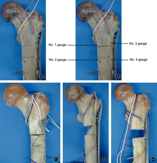
Five fracture models of the femur with four types of internal fixations showing the locations of the gauges.
(a) Fracture model I fixed by proximal femoral locking plate.
(b) Fracture model II fixed by proximal femoral locking plate.
(c) Fracture model III fixed by proximal femoral nail.
(d) Fracture model IV fixed by dynamic condylar screw.
(e) Fracture model V fixed by dynamic hip screw.
Each specimen was fixed in a metal tube using polymethylmethacrylate to simulate single‐leg stance: the body of the femur was adducted 15° in the frontal plane and vertical at the sagittal plane, maintaining medial rotation of 5°∼10°23. The following three tests were performed on the control femur and model IV:
Axial compression test: A preload was circulated five times at a velocity of 10 mm/min, after which an axial dynamic load was added to the femur at a velocity of 10 mm/min from 0 to 1200 N. The compression load, head sinking displacement and strain values were recorded.
Torsional test: The femur was fixed by a jig designed by the present team to the testing machine to simulate single leg stance. A horizontally torsional load was added to the femur. The rotating direction was extorsion and the torsional moment was 10 Nm. The torsional moment and torsional angle were recorded.
Axial failure tests: Only model V was axially loaded to failure from 0 N at a velocity 10 mm/min. The failure load was recorded (Video S2).
The following conditions were classified as failure of internal fixation: fractures of the femur, screw penetrating the femoral head or neck and plastic deformation of internal fixation.
Statistical Analysis
The strain ratio was calculated as the ratio of strain on the fracture model and the control femur. The average torsional stiffness ratio was calculated as the ratio of segmental fracture model torsional stiffness and original femur torsional stiffness. SPSS version 16.0 software (SPSS, Chicago, IL, USA) was used to analyze the data. Statistical analyses were performed by using one‐way ANOVA and Tukey's post hoc least statistically significant difference criterion was applied to correct for multiple group comparisons. The level of statistical significance was defined as P < 0.05 between groups.
Results
Strain
Strain gauges 1 and 2
In each internal fixation group, the strain ratios of strain gauges 1 and 2 gradually declined along with declines in stability of fracture models (Figs 2, 3). The strain ratio of strain gauge 2 was lower than that of strain gauge 1. The differences between each internal fixation group in models I–III were statistically significant (t = 2.243, P < 0.05). However, there were no significant differences between the implant groups in models IV and V (t = 1.209, P > 0.05). Within the same implant group, the strain ratios of models I–III showed significant differences (t = 2.047, P < 0.05). In the DCS and DHS groups, the degree of decline was higher between models III and IV than between models I and III. However, in the PFN and PFLP groups, the declines in models I and IV did not differ significantly.
Figure 2.
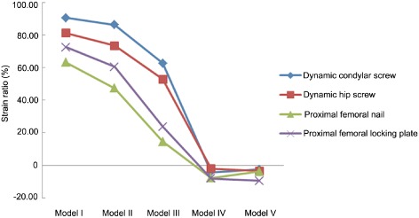
Comparison of strain ratios of all fracture models with different internal fixations on no. 1 strain gauge (n = 32). The differences between each internal fixation group in models I–III were statistically significant. However, there were no significant differences between the implant groups in models IV and V. Within the same implant group, the strain ratios of models I–III showed significant differences.
Figure 3.
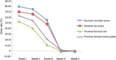
Comparison of strain ratios of all fracture models with different internal fixations on no. 2 strain gauge (n = 32). The differences between each internal fixation group in models I–III were statistically significant. However, there were no significant differences between the implant groups in models IV and V. Within the same implant group, the strain ratios of models I–III showed significant differences.
Strain gauges 3 and 4
The strain ratios of strain gauges 3 and 4 gradually declined along with declines in stability of fracture models in the PFN group (Figs 4, 5). The differences among models I, II and III were statistically significant (t = 2.984, P < 0.05). The strain ratios of strain gauges 3 and 4 initially declined and then increased along with declines in stability of the fracture models in the PFLP group. There were no significant differences in strain ratios among the models in the PFLP group (t = 1.778, P > 0.05). The strain ratios of DCS and DHS initially increased markedly and then declined, tension strain changing to compression strain. The differences in strain ratios among the models in the DCS and DHS group were significant (t = 3.821, P < 0.05). In models II–IV, the strain ratios of DCS and DHS were significantly different (t = 3.074, P < 0.05).
Figure 4.
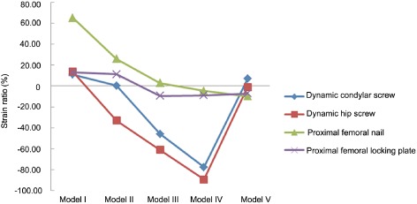
Comparison of strain ratios of all fracture models with different internal fixations on no. 3 strain gauge (n = 32). The differences among models I, II and III in PFN group were statistically significant. There were no significant differences in strain ratios among the models in the PFLP group. The strain ratios of DCS and DHS were significantly different in models II–IV.
Figure 5.
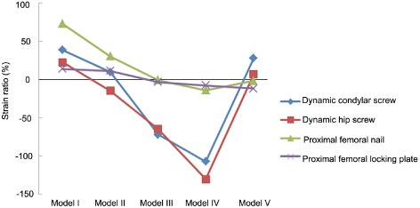
Comparison of strain ratios of all fracture models with different internal fixations on no. 4 strain gauge (n = 32). The differences among models I, II and III in PFN group were statistically significant. There were no significant differences in strain ratios among the models in the PFLP group. The strain ratios of DCS and DHS were significantly different in models II–IV.
Axial Compression Stiffness Ratios
The compression stiffness ratios declined along with declines in stability of fracture model (Fig. 6). In the PFN group, the compression stiffness ratios of fracture models III, IV and V were not significantly different (t = 1.704, P > 0.05). The compression stiffness ratios of models III and IV in the PFLP group were not significantly different (t = 1.208, P > 0.05). In the DCS and DHS groups, the compression stiffness ratios of each fracture model were significantly different (t = 2.117, P < 0.05). In models I–IV, the compression stiffness ratios of each implant group were significantly different (t = 3.365, P < 0.05). In model V, there was no significant difference between the DHS and PFLP groups (t = 0.572, P = 0.571), nor was there a significant difference between the other groups (P < 0.05).
Figure 6.
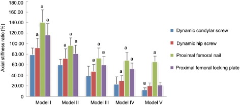
Comparison of axial stiffness ratio of all fracture models with different internal fixations (n = 32). a, there is a significant differences between this and the other three groups.
Torsional Stiffness Ratios
Within the same implant group, the torsional stiffness ratios of models II–V were not significantly different (t = 0.841, P > 0.05; Fig. 7). In models II–V, no significant differences were detected in torsional stiffness ratios between the DCS and PFLP groups (t = 0.468, P > 0.05). However, the torsional stiffness ratios of the DCS and PFLP groups were significantly different from those of the other implant groups (t = 4.026, P < 0.05).
Figure 7.
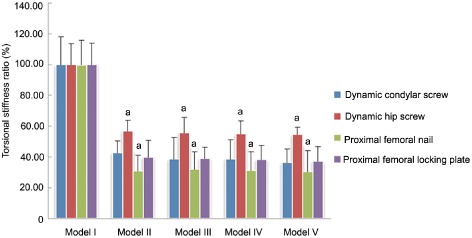
Comparison of torsional stiffness ratio of all fracture models with different internal fixations (n = 32). a, there is a significant differences between this and the other three groups.
Average Failure Load
The failure load of the PFN group was the highest (2811.36 ± 322.37 N compared with DHS group, 2364.67 ± 654.36 N; PFLP group, 1900.97 ± 372.28 N; and DCS group, 1570.90 ± 404.64 N). The failure load of each implant group was significantly different from the others (F = 3.639, P = 0.025; Fig. 8).
Figure 8.
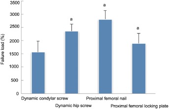
Comparison of the mean failure load of different internal fixation groups (n = 32). a, there is significant differences between this and the other three groups.
Discussion
Proximal femoral nail is a central type of intramedullary fixation. The bending moment of intramedullary fixation is less than that of extramedullary fixation, this reduces the bending stress imposed on internal fixation and the incidence of implant failure24, 25, 26, 27. Intramedullary fixation does not require complete integrity of the medial cortex, which is mainly attributable to the advantages of central fixation. With declines in stability of this fracture model, the stresses were gradually transmitted to the distal femur through the intramedullary nail, resulting in less stress on the medial cortex. Because the medial cortex lost contact in models IV and V, most of the stress was transmitted through the nail. Therefore, PFN can be used for both stable (Seinsheimer I and II) and unstable subtrochanteric fractures (Seinsheimer III and IV). Our results were similar to those of previous studies that have shown that intramedullary fixation is superior to extramedullary fixation for treating subtrochanteric fractures4, 18. These previous studies compared intramedullary nail and extramedullary fixation by fatigue testing, which differs from our test method; however, both studies showed that intramedullary fixation is a good choice for treating subtrochanteric fractures from different point of views.
The bending moment is greater than that of intramedullary fixation in the DHS and DCS types of extramedullary fixation. We found that extramedullary plates need the integrity of the subtrochanteric medial cortex. When the subtrochanteric medial cortex is integrated, the lateral plate acts as a tension band11. Stress is transmitted through the medial cortex, whereas the tension stress on the lateral side of the femur becomes compression stress. However, when the subtrochanteric medial cortex is missing (model IV), the subtrochanteric medial stress declines rapidly (gauges 1 and 2 showed this), and the stress quickly transfers to the plate on the lateral side of the femur. This leads to bending of the lateral plate, which leads to compression of the lateral cortex of the femur and high compression stress. In models II and III, the stress ratio of DHS was less than that of DCS, which is similar to the findings of Meislin et al.28. This is mainly related to the angle of the proximal screw.
The PFLP has several locking screws that increase the stability of the implant–femur construct. This construction is a type of “internal external fixator”29. The screws are firmly locked on the plate, generating high resistance strength to pull‐out and increasing the strength of the plate. A plurality of locking screws increase the stability and strength of the implant–femur construct and reduce the stress concentration because of the sharing role of the locking screws30. The stability of the PFLP–femur construct is conferred by each locking screw and this construct reduces damage to the periosteal blood supply under the plate, thus facilitating healing29. The medial strain of PFLP declined more evenly than that of DHS and DCS, which is mainly attributable to dispersion of the strain because of the locking screws. Because the tension band effect is not obvious, the variation in strain of the lateral cortex is small.
The axial compressive stiffness ratios of PFN in models III, IV and V were not significantly different, which could explain why stress is transmitted through the intramedullary nail when the subtrochanteric medial cortex is missing. Whatever the stability of the fracture model, PFN always had the highest axial compressive stiffness ratio and the failure load among the four kinds of internal fixations; these differences were statistically significant. This is similar to the findings of Forward et al.19. The axial compressive stiffness ratio and failure load of DHS were higher than those of DCS, which is similar to the results of Lundy et al.s study31. This is mainly attributable to the angle of the proximal lag screw of the DHS, which is greater than that of the DCS. The angle of the proximal lag screw of the DHS is better suited to the femoral neck‐shaft angle, resulting in the load on the proximal femur being transmitted to the lateral side of the femur through the sliding screw, thus reducing stress on the medial cortex. However, the axial compressive stiffness ratios of DHS and DCS decreased significantly in models IV and V; these differences were statistically significant. These findings indicate that DHS and DCS are not suitable for treating subtrochanteric fractures with the medial cortex missing or comminuted subtrochanteric fractures. The axial compressive stiffness ratio of PFLP was superior to that of DHS and DCS in models II, II and IV; this difference being statistically significant. These findings indicate that PFLP can fix transverse subtrochanteric fractures and fractures with the medial cortex missing. However, the axial compressive stiffness ratio of PFLP was similar to that of DHS in model V, whereas the failure load of DHS was greater than that of PFLP. We believe that there was no contact on the fracture site in model V, therefore the stress was transmitted through the plate. Under these conditions, the failure load of the implant–femur construct depends on the strength and stiffness of the implant, the number of screws and the activity between the screw and plate. DHS and PFLP both had their own strengths. Because the plate of DHS is thicker than that of PFLP, the strength and stiffness of DHS is greater than those of PFLP. There are more numerous proximal locking screws in PFLP than in DHS; however, the diameter of the proximal screws of DHS is much greater than in PFLP. In addition, the distal screws of PFLP are locking designed, whereas those of DHS are ordinary double cortical screws. Therefore, it is possible that the stiffness of DHS and PFLP are similar, but the failure load of DHS is higher than that of PFLP.
Within the same internal fixation group, the differences in torsional stiffness ratios were not statistically significant among models II to V, indicating that contact of fracture fragments has little effect on torsional stiffness1. There are only two screws in the distal part of PFN, whereas extramedullary fixation has four screws. In addition, the distal screws of PFN are far from the fracture site. This reduces the torsional stiffness ratio of PFN. Lack of fit with the proximal part of the femur reduces the torsional stiffness ratio of DCS. However, actual fracture lines are erratic, unlike the fracture line in our experiments, which is a shortcoming of our study.
Our results lead us to make some suggestions for the treatment of subtrochanteric fractures. For Seinsheimer I subtrochanteric fractures, four internal fixations can provide good stability. The biomechanical properties of PFN are the best and those of DCS the worst. The biomechanical properties of PFLP are superior to those of DHS. Because PFLP is designed so that the locking screw plays a stress‐sharing role, it is more suitable for osteoporotic subtrochanteric fractures.
For Seinsheimer IIIA subtrochanteric fractures, PFN and PFLP can provide reliable and stable fixation. If the medial cortex is restored, use of DCS could be considered; however, its stability is poorer than that of PFN and PFLP. Because DHS has only one proximal screw, which reduces its stability, DHS should not be considered for comminuted subtrochanteric fractures.
For Seinsheimer IV subtrochanteric fractures, only PFN provides stable fixation. If the fracture fragment is large, PFLP can also be used.
The limitations of this study include the following. First, we did not use fresh cadaver femurs for testing, which reduced the credibility of the results. However, one recent study has shown that embalmed and fresh frozen femurs have similar biomechanical properties; thus, embalmed femurs can be used in biomechanical testing instead of fresh frozen femurs32. Second, there is no callus on fracture sites in vitro. Third, because of the limitations of the experimental conditions, we could not simulate the muscles of the trochanteric region.
In Seinsheimer I fractures, IIIA fractures with the medial fragment removed and IIIA fractures with the medial fragment restored, the axial compressive stiffness ratio of PFLP was greater than that of DHS, whereas in Seinsheimer IV fractures, the axial compressive stiffness ratios of DHS and PFLP were not significantly different. However, the failure load of DHS was greater than that of PFLP. Hence, further experiments such as fatigue testing should be conducted to explore the differences in biomechanical properties between DHS and PFLP.
Supporting information
Disclosure: The authors declare no conflict of interest. No benefits in any form have been, or will be, received from a commercial party related directly or indirectly to the subject of this manuscript. This research has received subsidies from the National Natural Science Foundation of China (81102607), the Science and Technology Research Projects of Tianjin Municipal Health Bureau (11KG137, 12KG120) and the Key Technology R&D Program of Tianjin (13ZCZDSY01700).
References
- 1. Tencer AF, Johnson KD, Johnston DW, Gill K. A biomechanical comparison of various methods of stabilization of subtrochanteric fractures of the femur. J Orthop Res, 1984, 2: 297–305. [DOI] [PubMed] [Google Scholar]
- 2. Loizou CL, McNamara I, Ahmed K, Pryor GA, Parker MJ. Classification of subtrochanteric femoral fractures. Injury, 2010, 41: 739–745. [DOI] [PubMed] [Google Scholar]
- 3. Craig NJ, Sivaji C, Maffulli N. Subtrochanteric fractures. A review of treatment options. Bull Hosp Jt Dis, 2001, 60: 35–46. [PubMed] [Google Scholar]
- 4. Sims SH. Subtrochanteric femur fractures. Orthop Clin North Am, 2002, 33: 113–126. [DOI] [PubMed] [Google Scholar]
- 5. Koch JC. The laws of bone architecture. J Anat Am, 1917, 21: 177–198. [Google Scholar]
- 6. Tordis TG. Stress analysis of the femur. J Biomech, 1969, 2: 163–174. [DOI] [PubMed] [Google Scholar]
- 7. Wheeler DL, Croy TJ, Woll TS, Scott MD, Senft DC, Duwelius PJ. Comparison of reconstruction nails for high subtrochanteric femur fracture fixation. Clin Orthop Relat Res, 1997, 338: 231–239. [DOI] [PubMed] [Google Scholar]
- 8. Kaufer H. Mechanics of the treatment of hip injuries. Clin Orthop Relat Res, 1980, 146: 53–61. [PubMed] [Google Scholar]
- 9. Mahomed N, Harrington I, Kellam J, Maistrelli G, Hearn T, Vroemen J. Biomechanical analysis of the Gamma nail and sliding hip screw. Clin Orthop Relat Res, 1994, 304: 280–288. [PubMed] [Google Scholar]
- 10. Zickel RE. Nonunions of fractures of the proximal and distal thirds of the shaft of the femur. Instr Course Lect, 1988, 33: 173–179. [PubMed] [Google Scholar]
- 11. Bedi A, Toan Le T. Subtrochanteric femur fractures. Orthop Clin North Am, 2004, 35: 473–483. [DOI] [PubMed] [Google Scholar]
- 12. Utrilla AL, Reig JS, Muñoz FM, Tufanisco CB. Trochanteric gamma nail and compression hip screw for trochanteric fractures: a randomized, prospective, comparative study in 210 elderly patients with a new design of the gamma nail. J Orthop Trauma, 2005, 19: 229–233. [DOI] [PubMed] [Google Scholar]
- 13. Ramakrishnan M, Prasad SS, Parkinson RW, Kaye JC. Management of subtrochanteric femoral fractures and metastases using long proximal femoral nail. Injury, 2004, 35: 184–190. [DOI] [PubMed] [Google Scholar]
- 14. Nuber S, Schonweiss T, Ruter A. Stabilisation of unstable trochanteric femoral fractures. Dynamic hip screw (DHS) with trochanteric stabilisation plate vs. proximal femur nail (PFN). Unfallchirurg, 2003, 106: 39–47. [DOI] [PubMed] [Google Scholar]
- 15. Boldin C, Seibert FJ, Fankhauser F, Peicha G, Grechenig W, Szyszkowitz R. The proximal femoral nail (PFN)—a minimal invasive treatment of unstable proximal femoral fractures: a prospective study of 55 patients with a follow‐up of 15 months. Acta Orthop Scand, 2003, 74: 53–58. [DOI] [PubMed] [Google Scholar]
- 16. Pires RE, Santana EO Jr, Santos LE, Giordano V, Balbachevsky D, Dos Reis FB. Failure of fixation of trochanteric femur fractures: clinical recommendations for avoiding Z‐effect and reverse Z‐effect type complications. Patient Saf Surg, 2011, 5: 17. [DOI] [PMC free article] [PubMed] [Google Scholar]
- 17. Menezes DF, Gamulin A, Noesberger B. Is the proximal femoral nail a suitable implant for treatment of all trochanteric fractures? Clin Orthop Relat Res, 2005, 439: 221–227. [DOI] [PubMed] [Google Scholar]
- 18. Forward DP, Doro CJ, O'Toole RV, et al A biomechanical comparison of a locking plate, a nail, and a 95 degrees angled blade plate for fixation of subtrochanteric femoral fractures. J Orthop Trauma, 2012, 26: 334–340. [DOI] [PubMed] [Google Scholar]
- 19. Burnei C, Popescu G, Barbu D, Capraru F. Intramedullary osteosynthesis versus plate osteosynthesis in subtrochanteric fractures. J Med Life, 2011, 4: 324–329. [PMC free article] [PubMed] [Google Scholar]
- 20. Kim JW, Oh CW, Byun YS, et al A biomechanical analysis of locking plate fixation with minimally invasive plate osteosynthesis in a subtrochanteric fracture model. J Trauma, 2011, 70: E19–E23. [DOI] [PubMed] [Google Scholar]
- 21. Wang SL, Tan ZJ, Zhou QM, et al Using anatomic locking plate to fix intertrochanteric and subtrochanteric fracture involving femoral shaft. Zhonghua Gu Ke Za Zhi, 2012, 32: 626–630 (Chin). [Google Scholar]
- 22. Yang Y, Ma XL, Ma JX, et al Axial biomechanical difference between embalmed and PMMA proximal femur. Sheng Wu Yi Xue Gong Cheng Yu Lin Chuang, 2010, 14: 285–289 (Chin). [Google Scholar]
- 23. Bong MR, Patel V, Iesaka K, Egol KA, Kummer FJ, Koval KJ. Comparison of a sliding hip screw with a trochanteric lateral support plate to an intramedullary hip screw for fixation of unstable intertrochanteric hip fractures: a cadaver study. J Trauma, 2004, 56: 791–794. [DOI] [PubMed] [Google Scholar]
- 24. Curtis MJ, Jinnah RH, Wilson V, Cunningham BW. Proximal femoral fractures: a biomechanical study to compare intramedullary and extramedullary fixation. Injury, 1994, 25: 99–104. [DOI] [PubMed] [Google Scholar]
- 25. Anglen JO, Weinstein JN, American Board of Orthopaedic Surgery Research Committee . Nail or plate fixation of intertrochanteric hip fractures: changing pattern of practice. A review of the American Board of Orthopaedic Surgery Database. J Bone Joint Surg Am, 2008, 90: 700–707. [DOI] [PubMed] [Google Scholar]
- 26. Forte ML, Virnig BA, Eberly LE, et al Provider factors associated with intramedullary nail use for intertrochanteric hip fractures. J Bone Joint Surg Am, 2010, 92: 1105–1114. [DOI] [PubMed] [Google Scholar]
- 27. Radford PJ, Needoff M, Webb JK. A prospective randomised comparison of the dynamic hip screw and the gamma locking nail. J Bone Joint Surg Br, 1993, 75: 789–793. [DOI] [PubMed] [Google Scholar]
- 28. Meislin RJ, Zuckerman JD, Kummer FJ, Frankel VH. A biomechanical analysis of the sliding hip screw: the question of plate angle. J Orthop Trauma, 1990, 4: 130–136. [DOI] [PubMed] [Google Scholar]
- 29. Bottlang M, Feist F. Biomechanics of far cortical locking. J Orthop Trauma, 2011, 25 (Suppl. 1): S21–S28. [DOI] [PMC free article] [PubMed] [Google Scholar]
- 30. Latifi MH, Ganthel K, Rukmanikanthan S, Mansor A, Kamarul T, Bilgen M. Prospects of implant with locking plate in fixation of subtrochanteric fracture: experimental demonstration of its potential benefits on synthetic femur model with supportive hierarchical nonlinear hyperelastic finite element analysis. Biomed Eng Online, 2012, 11: 23. [DOI] [PMC free article] [PubMed] [Google Scholar]
- 31. Lundy DW, Acevedo JI, Ganey TM, Ogden JA, Hutton WC. Mechanical comparison of plates used in the treatment of unstable subtrochanteric femur fractures. J Orthop Trauma, 1999, 13: 534–538. [DOI] [PubMed] [Google Scholar]
- 32. Topp T, Müller T, Huss S, et al Embalmed and fresh frozen human bones in orthopedic cadaveric studies: which bone is authentic and feasible? Acta Orthop, 2012, 83: 543–547. [DOI] [PMC free article] [PubMed] [Google Scholar]
Associated Data
This section collects any data citations, data availability statements, or supplementary materials included in this article.


