Abstract
Neocortical areas communicate via extensive axonal projections, but the logic of information transfer is unresolved because the projections of individual neurons have not been systematically characterized. It is unknown whether individual neurons send projections only to single cortical areas, or instead distribute signals across multiple targets. Here we determined the projection patterns of 591 individual neurons in mouse primary visual cortex (V1) using whole-brain fluorescence-based axonal tracing and high-throughput DNA sequencing of genetically barcoded neurons (MAPseq). Projections were highly diverse and divergent, collectively targeting at least 18 cortical and subcortical areas. Most neurons target multiple cortical areas, often in non-random combinations, suggesting the existence of sub-classes of intracortical projection neurons. Thus the dominant mode of intracortical information transfer is not based on “one neuron – one target area” mapping. Instead, signals carried by individual cortical neurons are shared across subsets of target areas, and thus concurrently contribute to multiple functional pathways.
While the inputs received by a neuron drive its activity, its axonal projections determine its impact on other neurons. The axons of excitatory projection neurons residing in cortical layers 2/3, 5 and 6 of the neocortex are the main conduit by which signals are exchanged between cortical areas1. To date, no study has systematically investigated the principles by which individual neurons in any region of the mammalian neocortex distribute information to their targets. This knowledge is fundamental for establishing the logic of inter-areal communication and for constraining hypotheses about neural function and identification of putative sub-classes of neurons. Anatomical studies in macaque, cat and mouse, largely based on retrograde tracing methods, suggest an abundance of intracortical projection neurons in sensory neocortex whose axons appear to innervate single target areas2–6, raising the possibility that information may be distributed via ensembles of dedicated pathways that are functionally tailored to each target6–12. For example, neurons in mouse primary visual cortex (V1) that innervate the posteromedial (PM) or anterolateral (AL) area appear to match the spatial and temporal frequency preference of these target areas7,13,14. Similarly, neurons in the mouse primary somatosensory cortex projecting to either primary motor cortex or the secondary somatosensory area comprise largely non-overlapping populations with distinct physiological and functional properties6,9,10. These findings indicate that dedicated lines — specialized subpopulations of neurons that preferentially target a single downstream area (Fig. 1a, top) — may represent a fundamental mode of cortico-cortical communication. Alternatively, intra-cortically projecting neurons could broadcast to multiple targets4,5,15–19, either randomly (Fig. 1a, middle), or by targeting specific sets of areas (Fig. 1a, bottom). These three models of cortical architecture have different implications for inter-areal communication underlying sensory processing in hierarchical networks. We therefore set out to distinguish among them, using two anterograde anatomical approaches, whole-brain fluorescence-based axonal tracing and MAPseq, to map the long-range axonal projection patterns of individual neurons in mouse primary visual cortex (V1), an area that distributes visual information to multiple cortical and subcortical targets20–22.
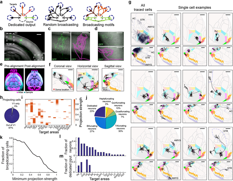
Figure 1: Brain-wide single-cell tracing reveals the diversity of axonal projection patterns of layer 2/3 V1 neurons, with most cells projecting to more than one target area.
(a) Three hypothetical modes of inter-areal information transfer from one area to its multiple targets. Neurons (arrows) could each project to a single area (top) or to several areas either randomly (middle) or in predefined projection patterns (bottom). (b) Maximum projection of a representative example GFP-filled neuron coronal view acquired by serial-section 2-photon microscopy. Auto-fluorescence from the red channel is used to show the brain’s ultrastructure (gray background). Scale bar = 600 μm. N = 71. (c-d) Higher magnification of the medial (c) and lateral (d) axonal arbor of the example cell. Scale bar = 300 μm. (e) Horizontal section through a sample brain (cyan) and Allen reference atlas (ARA; magenta) before (left) and after (right) rigid and non-rigid transformation of the brain to the atlas. (f) Coronal, sagittal and horizontal projections of the traced example cell overlaid in ARA space. Target cortical areas are coloured as indicated. Areas: A, anterior; AL: anterolateral; AM: anteromedial; LI: lateroitermediate; LM: lateral; P: posterior; PM: posteromedial; POR: postrhinal; RL: rostrolateral; TEA: temporal association; ECT: ectorhinal; PER: perirhinal. Scale bar = 1 mm. (g) Overlay of all traced single neurons (top left) and 11 example cells in Allen Reference Atlas (ARA) space; horizontal view (upper panel) and sagittal view (lower panel). Dashed outlines label non-visual target areas: AC: anterior cingulate cortex; STR, striatum; AMYG: amygdala. Note that these images are for illustration purposes only because a 2D projection cannot faithfully capture the true axonal arborisation pattern in 3D. Scale bar = 1 mm. (h) Pie chart illustrating the fraction of traced single neurons that project to at least one target area outside V1, where at least 1 mm of axonal innervation is required for an area to be considered a target. (i) Projection pattern of all GFP-filled V1 neurons targeted randomly (upper panel, n=31). The colour-code reflects the projection strengths of each neuron, determined as axon length per target area, normalized to the axon length in the target area receiving the densest innervation. Only brain areas that receive input form at least one neuron, as well as striatum, are shown. Areas: AUD: auditory cortex; ENT: entorhinal; HIPP: hippocampus; LA: lateral amygdala; RHIPP: retrohippocampal region; RS: retrosplenial. (j) The number of projection targets for every neuron that projects out of V1. (k) The proportion of cells targeting more than one area, when projection targets that receive projections weaker than the indicated projection strength are ignored. For each neuron, projection strengths are normalized to axon length in the target area receiving the densest innervation. (l) The fraction of neurons projecting to each of the 18 target areas of V1. (m) The fraction of neurons innervating a single target area (‘dedicated’ projection neurons) out of all neurons that innervate that area.
Fluorescence-based single neuron tracing
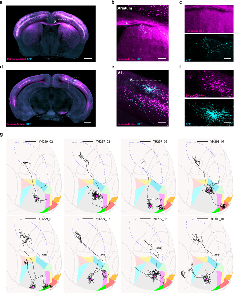
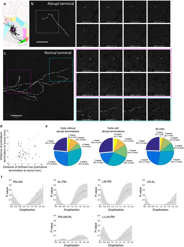
We first traced single-neuron projections using whole-brain fluorescence-based axonal reconstructions. We used single-cell electroporation of a GFP-encoding plasmid to label up to six layer 2/3 cells in the right visual cortex of each mouse. After allowing 3–10 days for GFP expression we imaged the axonal projections of the labeled neurons by whole-brain serial two-photon tomography with 1×1×10 μm resolution23,24 (Fig. 1b). We then traced each fluorescently-labeled cell (Fig. 1c,d; n = 71) and registered each brain to the Allen Reference Atlas25 (Fig. 1e,f). To assess axonal labelling with GFP, we electroporated neurons labelled retrogradely from the ipsilateral striatum, and in all cases observed axonal terminations therein (n = 9/9 cells; Extended Data Fig. 1), indicating a low false negative rate of filling axon collaterals to distal targets of V1 neurons. Nonetheless, to minimize any possible contribution of incomplete axonal filling, we excluded the contingent of reconstructed V1 neurons whose axon collaterals beyond V1 terminated abruptly without arborizing (n = 28; Extended Data Fig. 2; Supplemental Note 1), although the results below are robust to inclusion of these cells (Extended Data Fig. 2e). We did not exclude neurons with abrupt terminations of contralaterally projecting branches (compare ref6), instead restricting our analysis to ipsilaterally-projecting axons.
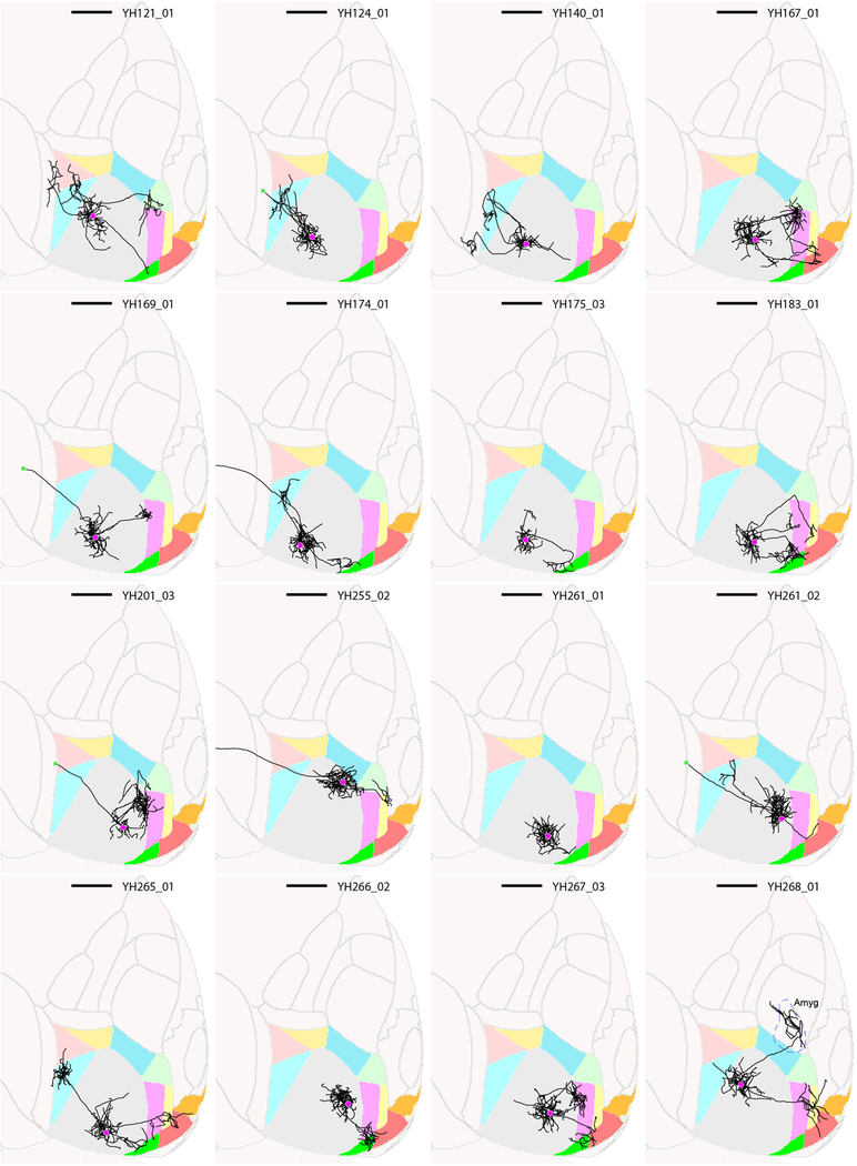
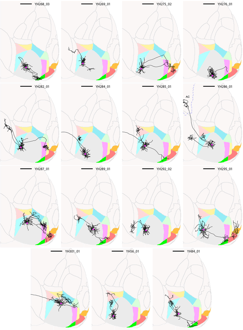
We analysed the ipsilateral projection patterns of 38 pyramidal neurons in layer 2/3, including 31 neurons in area V1 (Fig. 1g, Extended Data Fig. 3 and 4) and 7 neurons in nearby higher visual areas (Extended Data Fig. 5). Inspection of individual axonal arbors of V1 neurons revealed a high degree of projectional diversity with respect to the number and identity of target areas (Fig. 1g, Extended Data Fig. 3 and 4), which is obscured in bulk projection data20,21 (Fig. 1g, top left).
Almost all layer 2/3 cells projected out of V1 (Fig. 1h; 97%, 30/31) to one or more of 18 target areas in the telencephalon (Fig. 1i), typically innervating nearby cortical areas but occasionally also projecting to anterior cingulate cortex, striatum (Extended Data Fig. 1) and amygdala. To mitigate errors arising both from technical noise in atlas registration and from subject-to-subject variability in the boundaries between brain areas, we excluded low-confidence “buffer zones” of 100 μm around the area boundaries from analysis, and define as a “target” only those areas that received over 1 mm of axonal input from an individual cell (see Methods). Eighty-five percent of all projection patterns appeared only once, highlighting the diversity of long-range projections.
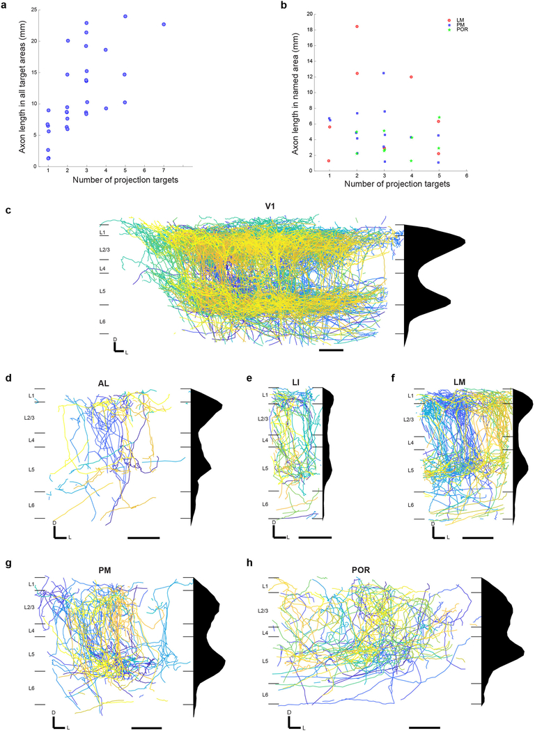
The majority of reconstructed layer 2/3 projection neurons sent axon collaterals to more than one target area (77%, 23/30), with some targeting up to seven areas (Fig. 1j). Although individual neurons innervated different target areas with different axonal densities, and thus might influence the computations in one area more than another, we found that a large fraction of broadcasting cells innervated more than one target with comparable strengths (Fig. 1k). Moreover, the total length of axon scaled with the number of target areas (average length per brain area = 4.6 ± 2.2 mm), such that the innervation density per target was, on average, similar irrespective of how many targets an axon innervated (Extended Data Fig. 6a,b). The innervation in higher visual areas was most dense in layers 2/3 and 5, consistent with recent reports26,27, often recapitulating the pattern of lateral axonal projections of layer 2/3 cells within V1 (Extended Data Fig. 6c–h).
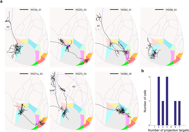
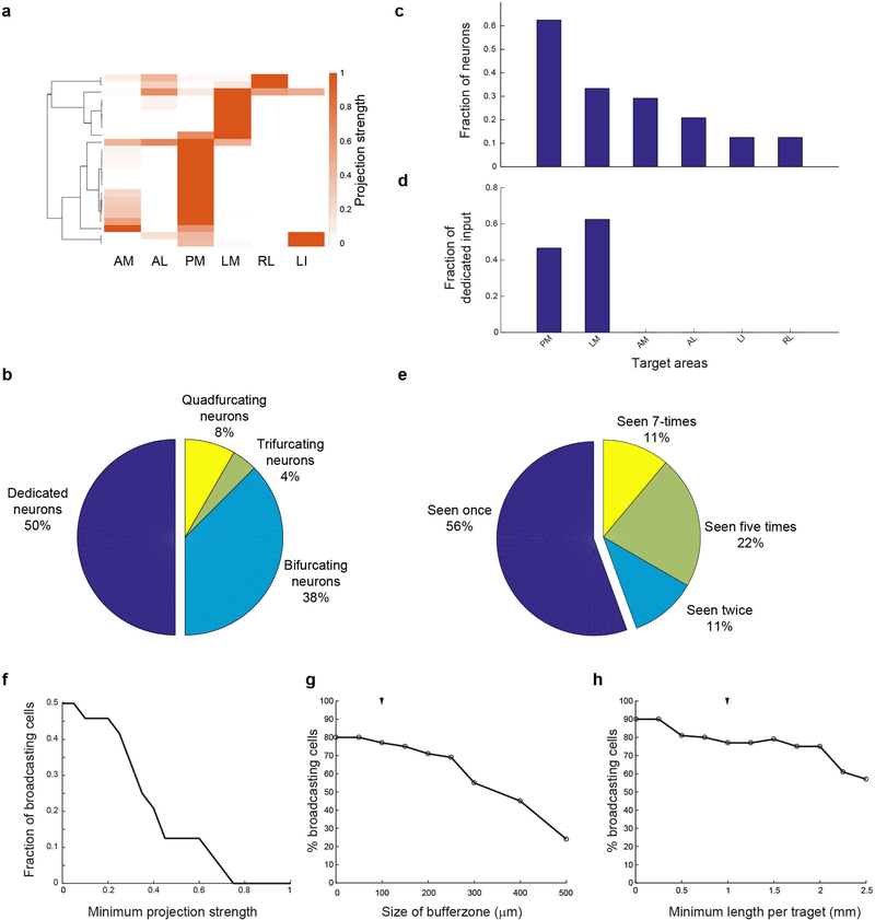
Posteromedial (PM), posterolateral (P), postrhinal (POR) and lateromedial (LM) visual areas were the most common targets of V1 neurons (Fig. 1l). Even when the analysis was restricted to neurons that projected to at least one of six nearby cortical visual areas (LI, LM, AL, PM, AM, RL), we found that half projected to two or more of these areas (Extended Data Fig. 7a–e). The fraction of input provided by dedicated projection neurons to any area comprised no more than 25% of the total (Fig. 1m), and most target areas received no dedicated input. These conclusions were robust to changes in the size of the border exclusion zone between neighbouring areas and the minimum projection strength in the target area (Extended Data Fig. 7f–h). Similar to projections from V1, all seven reconstructed neurons whose cell bodies resided in nearby higher visual areas also projected to more than one target area (Extended Data Fig. 5). Our results thus reveal that most layer 2/3 neurons distribute information to multiple areas, rather than projecting to single targets.
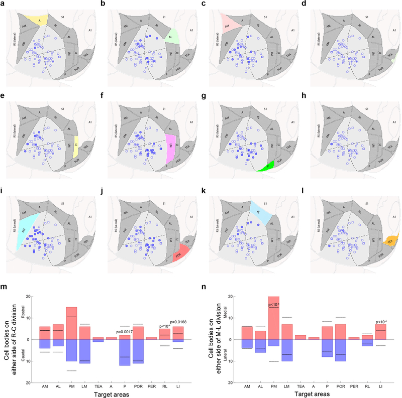
Interestingly, cell body location within V1 was predictive of projection target for some recipient areas (Extended Fig. 8). Given the retinotopic organization of V1, this suggest that visual information from different parts of visual field may be preferentially distributed to specific target areas, consistent with recent findings28.
High-throughput MAPseq tracing
We next investigated whether broadcasting cells choose their cortical target areas independently, or whether they target specific subsets of areas. While targeting different combinations of areas distinguishes individual V1 projection neurons (Fig. 1), their classification into putative sub-types requires a demonstration of higher-order projectional structure within the population. We define higher-order structure in terms of the connection patterns predicted by the per-neuron (first order) probability of projecting to each target. For example, if the probability of any given neuron projecting to area A is 0.5 and the probability of projecting to area B is also 0.5 then we would expect P(A∩B)=P(A)*P(B)=0.25 of all neurons to project to both A and B if the decisions to target these areas are independent. Significant deviations from this expectation would indicate organization into non-random projection motifs. Probing for high order structure requires large datasets, because, if a sample size of N neurons is required to estimate the first order probabilities, then a sample size of N2 is needed to estimate pairwise probabilities with comparable accuracy. Although single neuron reconstruction provides unrivaled spatial resolution, despite increases in throughput for data acquisition17,29, the tracing of axons remains highly labor intensive.
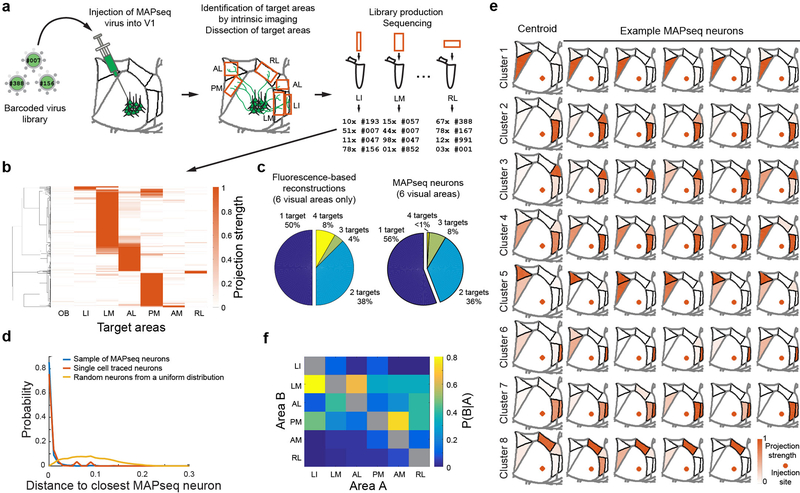
We therefore used a higher throughput strategy, MAPseq30, to obtain the required number of single neuron projections for higher-order statistical analysis. In a MAPseq experiment, hundreds or thousands of neurons are labeled uniquely with random RNA sequences (barcodes) by a single injection of a library of barcoded Sindbis virus (Supplemental Note 2). The barcodes are expressed and then actively transported into the axonal processes of each labeled neuron, where they can be read out by high throughput barcode sequencing after dissection of potential target areas. The abundance of each barcode sequence in each area serves as a measure of the projection strength of the corresponding barcode-labeled neuron. MAPseq thus simultaneously maps the projections of all labeled neurons to dissected target areas, and therefore allows in-depth analysis of projections to a smaller set of targets.
We used MAPseq to map the projection patterns of 553 neurons from V1 to six higher visual areas — LI, LM, AL, AM, PM and RL — that can be identified reliably by intrinsic signal imaging in vivo and dissected ex vivo for barcode sequencing (Fig. 2a,b; Extended Data Fig. 9; see Methods). To avoid virus spillover from V1 into adjacent areas, we made small focal injections of the MAPseq virus to yield 100–200 traced cells per animal. Consistent with the analysis of fluorescence-based single neuron reconstructions restricted to the six higher visual areas (Fig. 2c, left), almost half (44%) of all MAPseq neurons projected to more than one area (Fig. 2c, right). Furthermore, the projection patterns obtained by fluorescence-based tracing were statistically indistinguishable from those obtained by MAPseq (using a bootstrap procedure; see Supplemental Note 3), whereas randomly generated neurons with projection strengths sampled from a uniform distribution were markedly different (Fig. 2d). Thus the findings from the MAPseq dataset were consistent with those from single neuron tracing.
Figure 2: MAPseq projection mapping reveals a diversity of projection motifs.
(a) Overview of the MAPseq procedure. Six target areas were chosen for analysis: LI, LM, AL, PM, AM and RL. (b) Projection strength in the six target areas, as well as the olfactory bulb (OB) as a negative control, of 553 MAPseq-mapped neurons. Projection strengths per neuron are defined as the number of barcode copies per area, normalized to the efficiency of sequencing library generation and to the neuron’s maximum projection strength (n=4 mice). (c) Number of projection targets of V1 neurons when considering the six target areas only, based on the fluorescence-based axonal reconstructions (left) or the MAPseq data (right). (d) Distribution of cosine distances obtained by a bootstrapping procedure (1000 repeats) between MAPseq neurons (blue), fluorescence-based single neuron reconstructions and MAPseq neurons (orange), or random neurons (with projection strengths sampled from a uniform distribution) and MAPseq neurons (yellow). The distance distributions obtained from MAPseq neurons and fluorescence-based single-neuron reconstructions are statistically indistinguishable (Kolmogorov-Smirnov one-sided two sample test; p=0.94; α=0.05), whereas the distributions obtained from both MAPseq neurons or fluorescence-based reconstructed neurons are statistically different form the distribution obtained using random neurons (Kolmogorov-Smirnov two sample test; p<10−3; α=0.05). (e) Centroids and example cells for eight clusters obtained by k-means clustering of all MAPseq cells using a cosine distance metric. Target areas are coloured to indicate the projection strength of the plotted neuron. Projections strengths are normalize as in (b). (f) The probability of projecting to one area (Area A) given that the same neuron is projecting to another area (Area B) based on the MAPseq dataset.
We first catalogued the diversity of single neuron projection patterns from V1 to six higher visual areas by unsupervised clustering of the MAPseq dataset (k-means clustering with a cosine distance metric). These projectional data were best described by eight clusters (Fig. 2e, Extended Data Fig. 10), of which all but one contained cells targeting more than one area. The most common partners for broadcasting neurons were LM and PM, consistent with the fact that a large fraction of neurons targeted these areas and the suggestion of LM22 and PM as integrative hubs of V1 signals, akin to monkey V2 (Fig. 2f).
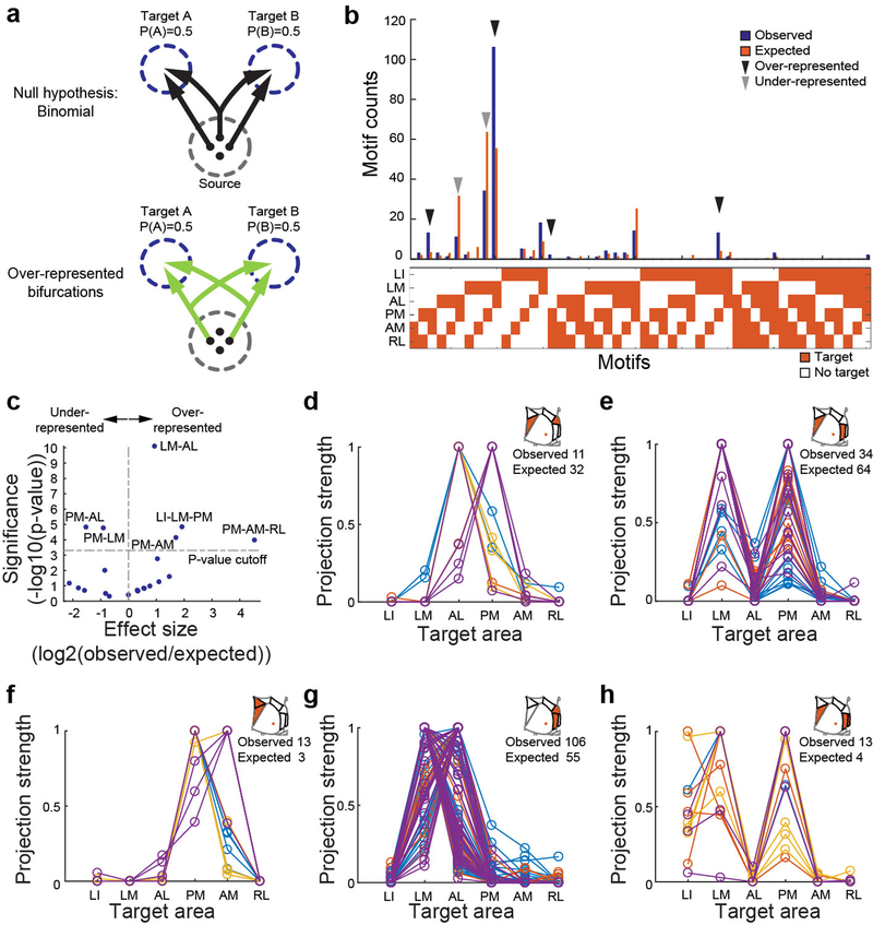
To uncover the existence of non-random projection motifs in the MAPseq dataset, we measured the likelihood of specific bi-, tri- or quadfurcations, by comparing them to expected probabilities of these divergent projections (assuming independence between each projection type; Fig. 3a,b). This analysis identified six projection motifs that were significantly over- or under-represented after a correction for multiple comparisons (Bonferroni adjustment; Fig. 3b,c). Together, these six projection motifs represented 73% of all broadcasting cells identified by MAPseq. Therefore the majority of V1 cells projecting to multiple target areas do so in a non-random manner, suggesting that broadcasting motifs reflect several sub-classes of projection neurons for divergent information transfer from V1 to higher visual areas.
Figure 3: Over- and under-represented projection motifs of neurons in primary visual cortex.
(a) The null hypothesis of independent projections to two target areas (left) and an example deviation (over-represented bifurcation) from the null hypothesis (right). (b) The observed and expected abundance of all possible bi-, tri- and quadfrucation motifs in the MAPseq dataset. Significantly over- or under-represented motifs, based on a binomial test with Bonferoni correction (see Methods), are indicated by black and grey arrowheads, respectively. N=553 neurons from 4 animals. (c) Statistical significance of over- and under-represented broadcasting motifs and associated effect sizes, based on a binomial test with Bonferoni correction (see Methods). N=553 neurons from 4 animals. (d-h) The projection strengths of the individual neurons (one per line) giving rise to the six under-represented (d,e) or over-represented (f-h) projection motifs. For each neuron, the projections strength in each target area is normalized to the neuron’s maximum projection strength. Lines of the same color represent neurons mapped in the same brain (n=4 mice).
The most under-represented broadcasting motif was the bifurcation between areas PM and AL (Fig. 3d). These two areas exhibit distinct visual response properties13,14 and receive functionally specialized input from V17, consistent with the idea of exclusive projections from V1 into these areas. Moreover, the under-represented population of neurons that do project to both PM and AL was further split into two groups according to projection strength, one that primarily innervates PM and another that primarily innervates AL (Fig. 3d). A second under-represented motif is the bifurcation between PM and LM (Fig. 3e). In contrast to the PM-AL bifurcation, however, the detected PM-LM projecting neurons do not separate cleanly into two classes. Our findings therefore provide an anatomical substrate for the previously reported functional dichotomy of areas AL and PM, and suggest that a few ‘dedicated’ output channels can co-exist with a preponderance of broadcasting cells co-innervating multiple targets.
In addition to the two under-represented projectional motifs, we also identified four over-represented motifs, i.e. combinations of target areas receiving more shared input from individual V1 neurons than expected from first-order projection statistics (Fig. 3f–h). Cells jointly innervating PM and AM were significantly more abundant than expected by chance (Fig. 3f). Resolving the projection strengths within this motif revealed two subpopulations of neurons, one innervating PM more than AM, the other innervating the two areas with similar strength. Moreover, neurons bifurcating to LM and AL were also highly over-represented (Fig. 3g) and comprised the most abundant class of broadcasting cells (Fig. 3b). The most significantly over-represented trifurcation motif was the projection to PM, LM and LI, comprising a relatively homogenous population that projects to LM and PM with similar strengths while slightly less to LI (Fig. 3h). Finally, we discovered the over-representation of the PM-AM-RL trifurcation, but it appeared only rarely in our dataset (Fig. 3b). These motifs did not arise from false negatives (undetected connections) or false positives (Supplemental Note 4; Extended Data Fig. 2f).
These projectional data have implications for the categorization of higher visual areas into putative streams of visual processing in mouse neocortex. Areas AL and PM on the one hand, and LM and LI on the other, have been suggested to belong to dorsal and ventral processing streams in the mouse visual system, respectively31–33. Given that these areas receive a high degree of shared input (e.g. LM-PM bifurcation, even if underrepresented, still abundant; AL-LM bifurcation; PM-LM-LI trifurcation), such a distinction is unlikely to originate as a result of segregated V1 input into these areas.
Discussion
In summary, our results reveal some of the principles by which single neurons in one cortical area distribute information to downstream target areas. Almost all layer 2/3 pyramidal cells projected outside of V1, indicating that V1 neurons concurrently engage in local and distal computations. We found that the single neuron projections beyond V1 were highly diverse, innervating up to seven targets, predominantly in specific, non-random combinations (Extended Data Fig. 10g,f). These results suggest a functional specialization of subpopulations of projection cells beyond ‘one neuron – one target area’ mapping.
The fraction of neurons in V1 that broadcast information to multiple targets is considerably greater than previously documented using retrograde methods2,5,16. This difference is unlikely caused by differences in the sensitivity with which these approaches detect the projections patterns of individual cells. Instead, anterograde tracing maps projections to many or all targets simultaneously, whereas retrograde tracing typically probes only two or three potential target sites at a time. Because the fraction of neurons projecting to any pair of targets selected for retrograde tracing is relatively low (typically <10%), most neurons will not be doubly labeled in any given experiment; only by sampling many potential targets in a single experiment can the true prevalence of broadcasting be uncovered. Indeed, if we simulate double retrograde tracing based on our MAPseq results, the fractions of bifurcating neurons are comparable to those observed using retrograde methods in primates2,5,16,18 (Supplemental Table 1).
We speculate that dedicated projection neurons — which comprise the minority of neurons in V1 — convey specialized visual information tailored to their target area, as suggested previously6–11. Indeed, the most under-represented projection motif from V1, the PM-AL bifurcation, innervates two target areas with distinct preferences for visual features13,14. In contrast, we suggest that the majority of cells encode information that is shared and in a form suitable for generating visual representations or multimodal associations across subsets of areas. Indeed, those target areas that are preferentially co-innervated by broadcasting neurons appear to have more similar visual response properties13,14. Broadcasting cells may also coordinate activity among the subset of areas they co-innervate, thus providing a signal that links different processing streams. The divergent nature of signal transmission from a primary sensory cortex to its targets may thus help constrain models of hierarchical sensory processing. The existence of distinct projection motifs that either avoid or favor subsets of target areas suggests the existence of sub-types of intracortical projection neurons and raises the question of how these specific, long-range connectivity patterns are established during development.
Methods
The anatomical single-cell tracing experiments were conducted at The Biozentrum, University of Basel, Switzerland. We licensed and performed all experimental procedures in accordance with Basel Canton animal welfare guidelines using both male and female adult (>8 weeks of age) C57BL/6 mice. Detailed protocols and all software are available at: http://mouse.vision/han2017
Fluorescence-based single neuron tracing
Two-photon guided single-cell electroporation.
We performed surgery as described previously34. Briefly, we anesthetized animals with a mixture of fentanyl (0.05 mg kg−1), midazolam (5 mg kg−1) and medetomidine (0.5 mg kg−1), and maintained stable anaesthesia by isoflurane (0.5% in O2). We performed all electroporations on a custom linear scanning 2-photon microscope, equipped to image both a green and a red channel and running ScanImage 5.135. For electroporation we used a patch pipette (12–16 MΩ) filled with plasmid DNA (pCAG-eGFP (Addgene accession 11150) or pAAV-EF1a-eGFP-WPRE (generous gift from Botond Roska; sequence file can be found in the Supplemental Materials, 100 ng/μl) and AlexaFluor 488 (50 μM) in intracellular solution, and delivered electroporation pulses (100 Hz, −14 V, 0.5 ms for 1 s) with an Axoporator 800A (Molecular Probes) when pushed against a target cell. We verified successful electroporation by dye filling of the cell body, and then sealed the skull with a chronic window using 1.5% agarose in HEPES-buffered artificial cerebrospinal fluid and a cover slip. We finally confirmed plasmid expression two days after electroporation by visualization of GFP epifluorescence through the chronic imaging window. Three to 10 days after electroporation, we transcardially perfused anesthetized mice with 10 ml 0.9% NaCl followed by 50 ml 4% paraformaldehyde in 0.1 M phosphate buffer (pH 7.4). We removed the brains from the skull and post-fixed them in 4% paraformaldehyde overnight at 4 °C. We then stored the fixed brains in PBS at 4 °C until imaging with serial-section 2-photon tomography.
Serial-section 2-photon tomography.
We embedded the fixed brains in 5% oxidised agarose (derived from Sigma Type I agarose) and covalently cross-linked the brain to the agarose by incubation in an excess of 0.5–1% sodium borohydrate (NaBH4, Sigma) in 0.05 M sodium borate buffer overnight at 4°C. We then imaged embedded brains using a TissueVision 2-photon scanning microscope23,36, which cut physical sections of the entire brain every 50 μm coronally, and acquired optical sections every 10 μm in two channels (green channel: 500–560 nm; red channel: 560–650 nm) using 940 nm excitation laser light (Mai Tai eHP, Spectraphysics). Each imaged section is formed from overlapping 800×800 μm “tiles”. We imaged with a resolution of 1 μm in x and y and measured an axial point spread function of ~5 μm FWHM using ScanImage 5.1.
Image processing and cell tracing.
We stitched raw image tiles using a custom MATLAB-based software, StitchIt. StitchIt applies illumination correction based on the average tiles for each channel and optical plane, and subsequently stitches the illumination-corrected tiles from the entire brain. We then navigated through the stitched brain space using MaSIV (https://github.com/alexanderbrown/masiv), a MATLAB-based viewer for very large 3-D images, and traced axons using a custom, manual neurite-tracer extension for MaSIV. The tracer was not blinded, as no comparison across experimental conditions was to be performed. No power calculations were performed.
To assign each voxel of the imaged brains to a brain area, we segmented each brain using areas defined by the Allen Reference Atlas (ARA, Common Coordinate Framework v3; © 2015 Allen Institute for Brain Science. Allen Brain Atlas API. Available from: brain-map.org/api/index.html), after smoothing with a single pass of an SD=0.5 voxel Gaussian kernel using the Nifty “seg-maths” tool as described previously37. Briefly, we downsampled one imaging channel to a voxel size of 25 μm and converted it to MHD format using StitchIt. We then registered the volume to the ARA average template brain using Elastix38 by applying rigid affine transformation followed by non-rigid deformation with parameters as described previously39,40. We examined registration quality using a custom Python/PyQt5 application, Lasagna, which overlays the Allen template brain and the registered sample brain and is extendable to allow the overlay of traced cells, or the overlay of ARA area borders onto a down-sampled brain. In order to transform the traced cells into ARA space (sample to ARA) we calculated the inverse transform to the one calculated by Elastix (ARA to sample) and applied this to the traced points.
Analysis of traced neurons.
To avoid potential incomplete filling of neurons from biasing the results of our analyses, we excluded cells with non-arborizing primary branches in the ipsilateral hemisphere from the analysis. Out of a total of 71 traced cells, we excluded 28 cells that exhibited abrupt, non-callosal terminations, as well as 5 cells that were backlabeled from the striatum, thus restricting our analysis to ipsilateral projection patterns of 31 cells in V1 and 7 in other higher visual areas. Moreover, axonal branches terminating contralaterally or after entering the corpus callosum were considered as callosal terminations and were included in the analysis (compare ref6). We calculated the first order projection statistics only using the ARA-registered cells that satisfied these criteria. To reduce any artifacts associated with ARA registration or individual brain variability in boundaries between brain areas, we excluded any axon within 50 μm from any brain area boundary from the analysis. We then calculated the projection strength of each neuron to each area as the total length of axon of that neuron in an area. To determine the number of projection targets for every cell, we used a minimum projection strength of 1 mm axon length per target area.
MAPseq
MAPseq sample processing.
To define the V1 injection site and target higher visual areas LI, LM, AL, PM, AM and RL, we used optical imaging of intrinsic signals as previously described13,41. Briefly, we first implanted a customized head plate and then thinned the skull to increase its transparency. After 2–3 days of recovery, we sedated the mice (chlorprothixene, 0.7 mg/kg) and lightly anesthetized them with isoflurane (0.5–1.5% in O2), delivered via a nose cone. We illuminated visual cortex with 700 nm light split from an LED source into 2 light guides, performing imaging with a tandem lens macroscope focused 250–500 μm below the cortical surface and a bandpass filter centered at 700 nm with 10 nm bandwidth (67905; Edmund optics). We acquired images at 6.25 Hz with a 12- bit CCD camera (1300QF; VDS Vosskühler), frame grabber (PCI-1422; National Instruments) and custom software written in LabVIEW (National Instruments). We visually stimulated the contralateral eye of mice with a monitor placed at a distance of 21 cm and presented 25–35° patches of 100% contrast square wave gratings with a temporal frequency of 4 Hz and a spatial frequency of 0.02 cycles per degree for 2 s followed by 5 s of grey screen (mean luminance of 46 cd/m2). To establish a coarse retinotopy of the targeted area, we alternated the position of the patches: we used two different elevations (approx. 0 and 20°) and two different azimuths (approx. 60 and 90°); at each position we acquired at least 17 trials. We obtained intrinsic signal maps by averaging the responses during the stimulation time using ImageJ (National Institute of Mental Health, NIH) and mapping the location of the estimated spots of activation onto a previously acquired blood vessel picture.
We then pressure injected (Picospritzer III, Parker) 100 nl of 1×10¹⁰ GC/ml barcoded MAPseq Sindbis virus30 with a diversity of >8×10⁶ different barcode sequences unilaterally at a depth of 100–200 μm from the brain surface into V1 of a total of four 8–10 week old C57BL/6 females. In addition, we labeled the six higher visual areas by placing a DiI-coated micropipette into retinotopically matched positions according to intrinsic signal maps. For this, we allowed 2–5 μl of a 2.5 mg/ml DiI (Invitrogen D3911) in ethanol solution to dry on the outside of a pulled micropipette tip until some DiI crystals were visible. Mice were sacrificed 44–48 hours post-injection by decapitation, and their brain immediately extracted and flash frozen on dry ice.
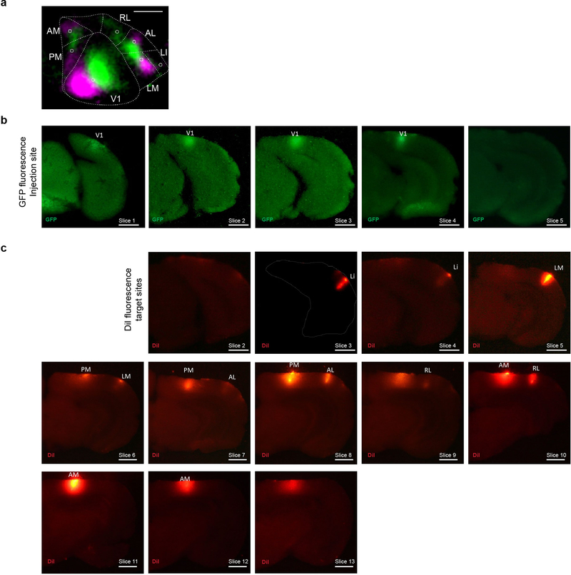
We cut 180 μm thick coronal sections using a cryostat at −10°C blade and sample holder temperature, and melted each slice onto a clean microscope slide before rapidly freezing it on dry ice again. We then dissected each target area and the injection site using cold scalpels while keeping the brain sections frozen on a metal block cooled to approximately −20°C in a freezing 2.25M CaCl2 bath42. During dissection, we identified each dissected area using a fluorescent dissection microscope to visualize viral GFP expression and DiI stabs labeling each target area (Extended Data Fig. 7). Throughout the procedure, we took care to avoid sample cross-contamination by never reusing tools or blades applied to different areas and changing gloves between samples. To measure noise introduced by contamination, we collected samples of the olfactory bulb from each brain, which served as a negative control.
We then processed the dissected samples for sequencing largely as previously described30, but pooling all samples after first strand cDNA synthesis. Briefly, we extracted total RNA from each sample using Trizol reagent (Thermo Fisher) according to the manufacturer’s instructions. We mixed the sample RNA with spike-in RNA (obtained by in vitro transcription of a double stranded ultramer with sequence 5’-GTC ATG ATC ATA ATA CGA CTC ACT ATA GGG GAC GAG CTG TAC AAG TAA ACG CGT AAT GAT ACG GCG ACC ACC GAG ATC TAC ACT CTT TCC CTA CAC GAC GCT CTT CCG ATC TNN NNN NNN NNN NNN NNN NNN NNN NAT CAG TCA TCG GAG CGG CCG CTA CCT AAT TGC CGT CGT GAG GTA CGA CCA CCG CTA GCT GTA CA-3’ (IDT)30) and reverse transcribed the RNA mixture using gene specific primer 5’-CTT GGC ACC CGA GAA TTC CAN NNN NNN NNN NNX XXX XXX XTG TAC AGC TAG CGG TGG TCG-3’, where X8 is one of >300 trueseq like sample specific identifiers and N12 is the unique molecular identifier, and SuperscriptIV reverse transcriptase (Thermo Fisher) according to the manufacturer’s instructions. We then pooled all first strand cDNAs, purified them using SPRI beads (Beckman Coulter) and produced double stranded cDNA as previously described43. We then treated the samples using ExonucleaseI (NEB) and performed two rounds of nested PCR using primers 5’-CTC GGC ATG GAC GAG CTG TA-3’ and 5’-CAA GCA GAA GAC GGC ATA CGA GAT CGT GAT GTG ACT GGA GTT CCT TGG CAC CC GAG AAT TCC A-3’ for the first PCR and primers 5’-AAT GAT ACG GCG ACC ACC GA-3’ and 5’- CAA GCA GAA GAC GGC ATA CGA-3’ for the second PCR using Accuprime Pfx polymerase (Thermo Fisher). Finally, we gel extracted the resulting PCR amplicons using Qiagen MinElute Gel extraction kit according to the manufacturer’s instructions and sequenced the library on a Illumina NextSeq500 high-output run at paired-end 36 using the SBS3T sequencing primer for paired-end 1 and the Illumina small RNA sequencing primer 2 for paired-end 2.
MAPseq data analysis.
Based on the sequencing results, we constructed a barcode matrix M of (number of barcodes) × (number of dissected areas) with entry Mi,j representing the absolute counts of barcode i in area j as previously described30. We de-multiplexed the sequencing results, extracted the absolute counts of each barcode in each sample based on the UMI sequence and error corrected the barcode sequences, before matching barcode sequences to the virus library and constructing matrix M by matching barcode sequences across areas. We then filtered the barcode matrix for ‘high-confidence’ cell bodies inside the dissected area of V1 by requiring a minimum of 10 counts in at least one target area, an at least 10-fold difference between the cell body location in V1 and the most abundant target area in data normalized to the efficiency of library production as measured by the amount of recovered spike-in RNA counts, and an absolute minimum barcode count of 300 in V1. We then normalized the raw barcode counts in each area by the relative spike-in RNA recovery to the olfactory bulb sample, merged the results from all four processed brains into a single barcode matrix and used this matrix for all further analysis.
To determine whether a particular neuron projected to any given target area, we chose a conservative threshold of at least 5 barcode counts, based on the highest level of barcode expression in the olfactory bulb negative control sample.
Calculation of statistical significance of projection motifs.
To calculate the statistical significance of broadcasting projection motifs, we compared against the simplest model in which we assumed that each neuron projected to each area independently. To generate predictions of this model, we first estimated the probability of projecting to each area, assuming independent projections. We define the probability P(Ai) that a given neuron projects to the ith area Ai as
where is the number of neurons in the sample that project to area Ai, i = 1..k for k analyzed target areas, and Ntotal is the total number of neurons in the sample.
In our MAPseq experiments, we do not have direct access to Ntotal, since for technical reasons we only include neurons that have at least one projection among the dissected targets. Since in principle some neurons might project to none of the areas dissected (see Fig. 3a), failure to include these would lead to an underestimate of Ntotal. However, assuming independence of projections we can infer Ntotal from the available measurements.
To estimate Ntotal, we first observe that
where Nobs is the total number of neurons observed to project to at least one area. For k=6 areas, we can expand this expression to
Noting that this is a quintic equation in Ntotal, we can use a root finder to solve for Ntotal numerically, and use the result to calculate P(Ai).
Using the derived Ntotal and P(Ai), we can calculate the p-value for every possible broadcasting motif by calculating the value of the binomial cumulative distribution function, for a total of Ntotal tries, the empirical number of observed counts (successes), and P(motif) assuming independent projections. We calculated the p-value of all possible bi-, tri- and quadfurcations, and determined significantly over- or under-represented broadcasting motifs at a significance threshold of α=0.05 after Bonferoni correction.
Data availability
All sequencing data are publicly accessible on the Sequence Read Archive under accessions SRR5274845 (ZL097 for mouse 4 and mouse 5) and SRR5274844 (ZL102 for mouse 6 and mouse 7). All single cell tracing results are accessible on http://mouse.vision/han2017 and will be uploaded to http://neuromorpho.org.
Code availability
All software are available at: http://mouse.vision/han2017
Extended Data
Extended Data Figure 1: Single-neuron tracing protocol efficiently fills axons projecting to the ipsilateral striatum.
We retrogradely labeled striatum projecting cells by stereotactically injecting cholera toxin subunit B conjugated with AlexaFluro594 or PRV-cre into the visual stri-atum of wild type mice or tdTomato reporter mice (Ai14, JAX), respectively (magenta). With visual guidance of two-photon microscopy, we electroporated single retrogradely labeled cells in V1 with a GFP expressing plasmid (cyan). (a) Coronal, maximum intensity projections of visual striatum. Scale bar = 1 mm. (b) Higher magnification view of the visual stratum. Scale bar = 0.2 mm. (c) Single channel images of the same axonal arbor as in (b). (d) Coronal maximum intensity projection containing V1. Scale bar = 1 mm. (e) Higher magnification view of V1. Scale bar = 0.2 mm. (f) Single channel images of V1. Scale bar = 0.2 mm. (g) Horizontal ARA-space projections of eight retrogradely labeled and electroportated cells. Cell ID numbers are indicated at the top right of each thumbnail. Scale bar = 1 mm. Note that one additional cell was retrogradely labeled and electroporated, which revealed its axonal projection to the striatum, but it is not shown because the brain was too distorted to allow accurate atlas registration.
Extended Data Figure 2: Some axonal branches terminate abruptly without arborizing, while other branches of the same neuron arborise extensively within different target areas and appear to be completely filled.
(a) Horizontal view of a representative cell in ARA space. The abrupt termination is labeled with a purple square. N=28 abruptly terminating cells. (b) The abrupt termination of the example cell shown as a maximum z-projection (left) and in the indi-vidual z-sections (right). (c) Two normal terminations of the same cell, shown as a maximum z-projection (left) and in two color-coded series of z-sections (right). (d) Distance of abrupt termi-nation from cell body vs. distance of farthest regular termination of the same cell. Dashed line indicates the unity line. (e) Pie charts illustrating the distribution of target numbers of all project-ing neurons without abrupt terminations (as shown in the main figures; left), of projecting cells with abrupt terminations (centre) and of all projecting cells (no abrupt terminations + abrupt ter-minations; right). (f) To test the effect of false negatives on our analyses, we simulated the ran-dom loss or gain of projections from the MAPseq dataset, while maintaining overall area projec-tion probabilities. N=553 neurons; 400 repeats. P-values based on a binomial test for all six pro-jection motifs determined as significantly over- or underrepresented in our dataset are plotted after removing (dropfraction < 1) or adding (dropfraction >1) connections. Mean (black line) and s.d. (shaded area) are indicated.
Extended Data Figure 3: Thumbnails of traced layer 2/3 V1 neurons, part 1.
Horizontal views of the ARA space are shown, and cell ID numbers are indicated at the top right of each thumbnail. Scale bar = 1 mm.
Extended Data Figure 4: Thumbnails of traced layer 2/3 V1 neurons, part 2.
Horizontal views of the ARA space are shown, and cell ID numbers are indicated at the top right of each thumbnail. Scale bar = 1 mm.
Extended Data Figure 5: Individual neurons in higher visual areas project to more than one target area.
(a) Thumbnails of all traced neurons with cell bodies not in V1. Brain area identity is color-coded as in Figure 1. Cell identity is indicated at the top right of each thumbnail. Scale bar = 1 mm. (b) Histogram of the number of target areas per cell.
Extended Data Figure 6: Density of axonal innervation by area and layer of V1 layer 2/3 projection neurons.
(a) Total axon length plotted as a function of the number of targets inner-vated by every V1 projection neuron. (b) Axon length in area LM, PM or POR plotted as a func-tion of the total number of targets innervated by each neuron projecting to the respective area. (c–h) The axons of V1 neurons in target areas most densely innervate layers 2/3 and 5, with some density in layer 1, but less in layers 4 and 6, often recapitulating the laminar axonal profile within V1. Coronal views of each area are shown in ARA space (left) and axonal arbors of each neuron innervating the area are color coded. Scale bar = 200 m. A histogram of the laminar innervation is shown (right). Note that cells with abrupt terminations outside the shown area were included in this analysis. Areas depicted are (c) V1, (d) AL, (e) LI, (f) LM, (g) PM, (h) POR. White matter axons are not shown.
Extended Data Figure 7: Conclusions from fluorescence-based single neuron tracing data hold true if analysis is restricted to subset of target areas.
(a) The projection patterns of re-constructed GFP-filled neurons when only the six target areas LI, LM, AL, PM, AM, and RL are considered. Projection strengths are normalized to the maximum projection of each neuron, and only neurons projecting to at least one target area are shown. (b) Pie chart showing the distribu-tion of target area numbers per projecting neuron. (c) Bar graph illustrating the fraction of all cells projecting to each target area. (d) The fraction dedicated input per area. (e) The number of times each binarized projection motif is observed. (f) The fraction of broadcasting cells as a function of the minimum projection strength (relative to the primary target) that each area needs to receive to be considered a target. (g) The fraction of broadcasting cells as a function of increasing buffer zones between areas within which axons are ignored, assuming a minimum projection of 1 mm of axon per target area. (h) The fraction of broadcasting cells as a function of the minimal amount of axon per area for it to be considered a target, assuming buffer zones of 100 μm width.
Extended Data Figure 8: Location of cell bodies in V1 as a function of their projection targets.
(a–l Horizontal views of ARA space are shown. The location of all traced V1 neurons are indicated as circles (cells with no abrupt terminations) or squares (cells with abrupt terminations). In every plot the cells projecting to the highlighted higher visual area are colored in solid blue. Target areas considered are (a) A, (b) AL, (c) AM, (d) ECT, (e) LI, (f) LM, (g) P, (h) PER, (i) PM, (j) POR, (k) RL, (l) TEA. (m-n) Quantification of cell body location in the rostro-caudal (m) and medio-lateral (n) direction. Dotted lines indicate expected number of cells based on a bootstrapping procedure, where we randomly selected neurons from the available positions to project to each area and repeated the process 10,000 times. P-values were derived from the boot-strapping probability distribution and are indicated for projection targets significantly deviating from this expectation (α=0.05). P-values below 10−4 are not exact and are therefore indicated as a range.
Extended Data Figure 9: MAPseq dissection strategy.
We identified the to-be-dissected high-er visual areas by performing intrinsic imaging of visual cortex in response to stimuli at different positions in the contralateral visual field and mapping the resulting changes in intrinsic signals. (a) A representative retinotopic map, with responses to the two 25° visual stimuli pseudocolored in green and magenta (stimulus 1 position: 90° azimuth, 20° elevation; stimulus 2 position: 60° azimuth, 20° elevation). Based on this map, we fluorescently labelled retinotopically matched positions in the to-be-dissected cortical areas with a DiI stab (white circles). Putative borders between the higher visual areas are indicated in dashed lines for orientation. Scale bar = 1 mm. N=4 animals. (b) The MAPseq virus injection site is discernible in consecutive frozen 180 m thick coronal sections, using GFP fluorescence. Scale bar = 1 mm. (c) DiI injections targeted to matched retinotopic positions in six target areas identified by intrinsic signal imaging. DiI epifluorescence images of each 180 m thick slice are shown, and dissected areas are labeled. Scale bar = 1 mm.
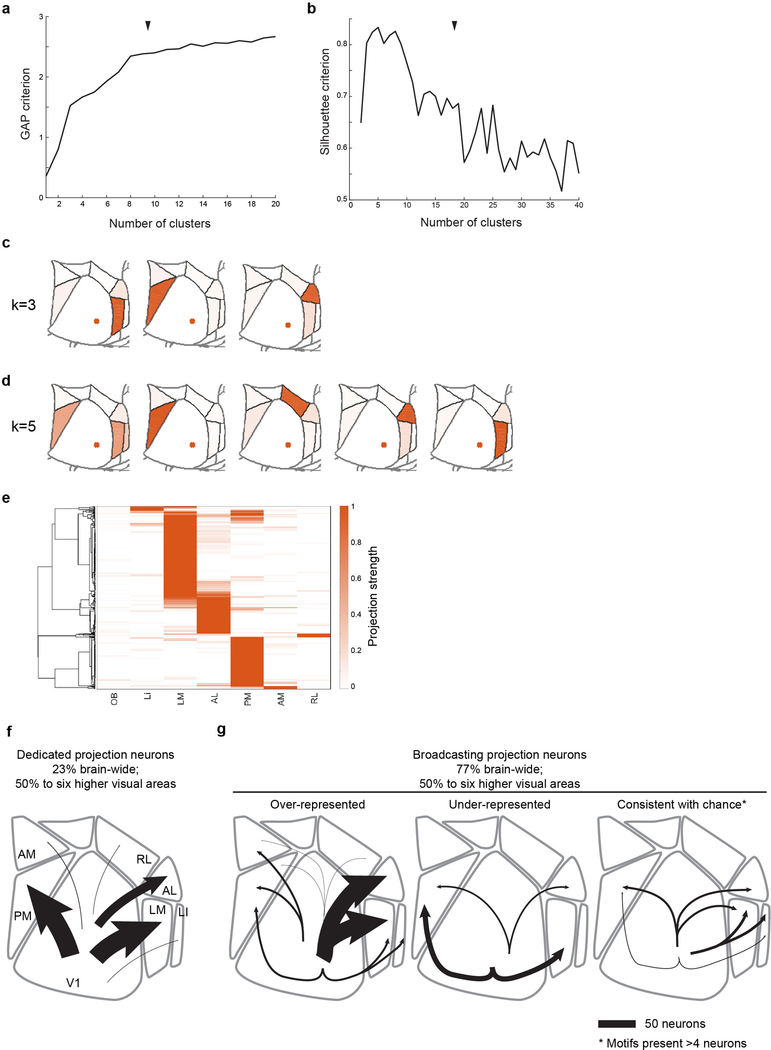
Extended Data Figure 10: Clustering of MAPseq data and data summary.
(a) GAP and (b) Silhouette criteria for k-means clustering of the MAPseq neurons as a function of the number of clusters. Black arrow heads indicate chosen number of clusters (k=8). (c,d) Centroids for alterna-tive, near-optimal cluster number choices with (c) k=3 and (d) k=5. (e) Hierarchical clustering results of the MAPseq dataset using a cosine distance metric. Color intensity in (c,d,e) indicated projection strengths. (f,g) Summary of single-neurons projections from V1. (f) Cells targeting single higher visual areas (dedicated projection neurons) comprise the minority of layer 2/3 V1 projection neurons. Among the areas analysed by MAPseq, dedicated projection neurons pre-dominantly innervate cortical areas LM or PM. (g) Cells projecting to two or more areas (broad-casting projection neurons) are the dominant mode of information transfer from V1 to higher visual areas. In the six areas analysed by MAPseq, broadcasting neurons innervate combinations of target areas in a non-random manner, including those that are more or less abundant than ex-pected by chance. Line width indicates the absolute abundance of each projection type as ob-served in the MAPseq dataset.
Supplementary Material
Acknowledgements
We would like to thank Ashley Juavinett, Longwen Huang, Sonja Hofer and Petr Znamenskiy for comments on the manuscript. Funding sources: National Institutes of Health (5RO1NS073129 to A.M.Z., 5RO1DA036913 to A.M.Z.); Brain Research Foundation (BRF-SIA-2014–03 to A.M.Z.); IARPA (MICrONS to A.M.Z.); Simons Foundation (382793/SIMONS to A.M.Z.); Paul Allen Distinguished Investigator Award (to A.M.Z.); PhD fellowship from the Boehringer Ingelheim Fonds (to J.M.K.); PhD fellowship from the Genentech Foundation (to J.M.K); Natioanl Natural Science Foundation of China (NSFC 31600847 to Y.H.); European Research Council (NeuroV1sion 616509 to T.D.M.-F.), and Swiss National Science Foundation (SNSF 31003A_169802 to T.D.M.-F.).
Footnotes
These authors contributed equally to the work as first authors.
These authors contributed equally to the work as senior authors.
The authors declare no conflict of interests.
References
- 1.Harris KD & Shepherd GMG The neocortical circuit: themes and variations. Nat. Neurosci 18, 170–181 (2015). [DOI] [PMC free article] [PubMed] [Google Scholar]
- 2.Nakamura H, Gattass R, Desimone R & Ungerleider L The modular organization of projections from areas V1 and V2 to areas V4 and TEO in macaques. J. Neurosci 13, (1993). [DOI] [PMC free article] [PubMed] [Google Scholar]
- 3.Segraves M & Innocenti G Comparison of the distributions of ipsilaterally and contralaterally projecting corticocortical neurons in cat visual cortex using two fluorescent tracers. J. Neurosci 5, (1985). [DOI] [PMC free article] [PubMed] [Google Scholar]
- 4.Rockland KS Collateral branching of long-distance cortical projections in monkey. J. Comp. Neurol 521, 4112–4123 (2013). [DOI] [PubMed] [Google Scholar]
- 5.Sincich LC & Horton JC Independent Projection Streams from Macaque Striate Cortex to the Second Visual Area and Middle Temporal Area. J. Neurosci 23, 5684–5692 (2003). [DOI] [PMC free article] [PubMed] [Google Scholar]
- 6.Yamashita T et al. Membrane Potential Dynamics of Neocortical Projection Neurons Driving Target-Specific Signals. Neuron 80, 1477–1490 (2013). [DOI] [PubMed] [Google Scholar]
- 7.Glickfeld LL, Andermann ML, Bonin V & Reid RC Cortico-cortical projections in mouse visual cortex are functionally target specific. Nat. Neurosci 16, 219–226 (2013). [DOI] [PMC free article] [PubMed] [Google Scholar]
- 8.Sato TR & Svoboda K The Functional Properties of Barrel Cortex Neurons Projecting to the Primary Motor Cortex. J. Neurosci 30, 4256–4260 (2010). [DOI] [PMC free article] [PubMed] [Google Scholar]
- 9.Chen JL, Carta S, Soldado-Magraner J, Schneider BL & Helmchen F Behaviour-dependent recruitment of long-range projection neurons in somatosensory cortex. Nature 499, 336–340 (2013). [DOI] [PubMed] [Google Scholar]
- 10.Yamashita T & Petersen CCH Target-specific membrane potential dynamics of neocortical projection neurons during goal-directed behavior. Elife 5, 2221 (2016). [DOI] [PMC free article] [PubMed] [Google Scholar]
- 11.Movshon JA & Newsome WT Visual response properties of striate cortical neurons projecting to area MT in macaque monkeys. J. Neurosci 16, 7733–7741 (1996). [DOI] [PMC free article] [PubMed] [Google Scholar]
- 12.Nassi JJ & Callaway EM Parallel processing strategies of the primate visual system. Nat. Rev. Neurosci 10, 360–372 (2009). [DOI] [PMC free article] [PubMed] [Google Scholar]
- 13.Andermann ML, Kerlin AM, Roumis DK, Glickfeld LL & Reid RC Functional specialization of mouse higher visual cortical areas. Neuron 72, 1025–1039 (2011). [DOI] [PMC free article] [PubMed] [Google Scholar]
- 14.Marshel JHH, Garrett MEE, Nauhaus I & Callaway EMM Functional Specialization of Seven Mouse Visual Cortical Areas. Neuron 72, 1040–1054 (2011). [DOI] [PMC free article] [PubMed] [Google Scholar]
- 15.Massé IO, Régnier P & Boire D in Axons and Brain Architecture 93–116 (2016). doi: 10.1016/B978-0-12-801393-9.00005-0 [DOI] [Google Scholar]
- 16.Bullier J & Kennedy H Axonal bifurcation in the visual system. Trends Neurosci. 10, 205–210 (1987). [Google Scholar]
- 17.Economo MN et al. A platform for brain-wide imaging and reconstruction of individual neurons. Elife 5, 13 (2016). [DOI] [PMC free article] [PubMed] [Google Scholar]
- 18.Weisenhorn DMV, Ilung RB & Spatz WB Morphology and connections of neurons in area 17 projecting to the extrastriate areas mt and 19DM and to the superior colliculus in the monkey Callithrix jacchus. J. Comp. Neurol 362, 233–255 (1995). [DOI] [PubMed] [Google Scholar]
- 19.Ding S-L, Van Hoesen G & Rockland KS Inferior parietal lobule projections to the presubiculum and neighboring ventromedial temporal cortical areas. J. Comp. Neurol 425, 510–530 (2000). [DOI] [PubMed] [Google Scholar]
- 20.Zingg B et al. Neural networks of the mouse neocortex. Cell 156, 1096–1111 (2014). [DOI] [PMC free article] [PubMed] [Google Scholar]
- 21.Oh SW et al. A mesoscale connectome of the mouse brain. Nature 508, 207–214 (2014). [DOI] [PMC free article] [PubMed] [Google Scholar]
- 22.Wang Q & Burkhalter A Area map of mouse visual cortex. J. Comp. Neurol 502, 339–357 (2007). [DOI] [PubMed] [Google Scholar]
- 23.Ragan T et al. Serial two-photon tomography for automated ex vivo mouse brain imaging. Nat. Methods 9, 255–258 (2012). [DOI] [PMC free article] [PubMed] [Google Scholar]
- 24.Osten P & Margrie TW Mapping brain circuitry with a light microscope. Nat. Methods 10, 515–523 (2013). [DOI] [PMC free article] [PubMed] [Google Scholar]
- 25.Lein ES et al. Genome-wide atlas of gene expression in the adult mouse brain. Nature 445, 168–176 (2007). [DOI] [PubMed] [Google Scholar]
- 26.D’Souza RD, Meier AM, Bista P, Wang Q & Burkhalter A Recruitment of inhibition and excitation across mouse visual cortex depends on the hierarchy of interconnecting areas. Elife 5, e19332 (2016). [DOI] [PMC free article] [PubMed] [Google Scholar]
- 27.Yang W, Carrasquillo Y, Hooks BM, Nerbonne JM & Burkhalter A Distinct Balance of Excitation and Inhibition in an Interareal Feedforward and Feedback Circuit of Mouse Visual Cortex. J. Neurosci 33, 17373–17384 (2013). [DOI] [PMC free article] [PubMed] [Google Scholar]
- 28.Zhuang J et al. An extended retinotopic map of mouse cortex. Elife 6, e18372 (2017). [DOI] [PMC free article] [PubMed] [Google Scholar]
- 29.Gong H et al. High-throughput dual-colour precision imaging for brain-wide connectome with cytoarchitectonic landmarks at the cellular level. Nat. Commun 7, 12142 (2016). [DOI] [PMC free article] [PubMed] [Google Scholar]
- 30.Kebschull JM et al. High-Throughput Mapping of Single-Neuron Projections by Sequencing of Barcoded RNA. Neuron 91, 975–987 (2016). [DOI] [PMC free article] [PubMed] [Google Scholar]
- 31.Wang Q, Sporns O & Burkhalter A Network Analysis of Corticocortical Connections Reveals Ventral and Dorsal Processing Streams in Mouse Visual Cortex. J. Neurosci 32, (2012). [DOI] [PMC free article] [PubMed] [Google Scholar]
- 32.Smith IT, Townsend LB, Huh R, Zhu H & Smith SL Stream-dependent development of higher visual cortical areas. Nat. Neurosci 20, 200–208 (2017). [DOI] [PMC free article] [PubMed] [Google Scholar]
- 33.Murakami T, Matsui T & Ohki K Functional Segregation and Development of Mouse Higher Visual Areas. J. Neurosci 37, 9424–9437 (2017). [DOI] [PMC free article] [PubMed] [Google Scholar]
- 34.Pecka M, Han Y, Sader E & Mrsic-Flogel TD Experience-Dependent Specialization of Receptive Field Surround for Selective Coding of Natural Scenes. Neuron 84, 457–469 (2014). [DOI] [PMC free article] [PubMed] [Google Scholar]
- 35.Pologruto TA, Sabatini BL & Svoboda K ScanImage: flexible software for operating laser scanning microscopes. Biomed. Eng. Online 2, 13 (2003). [DOI] [PMC free article] [PubMed] [Google Scholar]
- 36.Mayerich D, Abbott L & McCormick B Knife-edge scanning microscopy for imaging and reconstruction of three-dimensional anatomical structures of the mouse brain. J. Microsc 231, 134–43 (2008). [DOI] [PubMed] [Google Scholar]
- 37.Niedworok CJ et al. aMAP is a validated pipeline for registration and segmentation of high-resolution mouse brain data. Nat. Commun 7, 711879 (2016). [DOI] [PMC free article] [PubMed] [Google Scholar]
- 38.Klein S, Staring M, Murphy K, Viergever MA & Pluim J elastix: A Toolbox for Intensity-Based Medical Image Registration. IEEE Trans. Med. Imaging 29, 196–205 (2009). [DOI] [PubMed] [Google Scholar]
- 39.Kim Y et al. Whole-Brain Mapping of Neuronal Activity in the Learned Helplessness Model of Depression. Front. Neural Circuits 10, 3 (2016). [DOI] [PMC free article] [PubMed] [Google Scholar]
- 40.Renier N et al. Mapping of Brain Activity by Automated Volume Analysis of Immediate Early Genes. Cell 165, 1789–1802 (2016). [DOI] [PMC free article] [PubMed] [Google Scholar]
- 41.Roth MM et al. Thalamic nuclei convey diverse contextual information to layer 1 of visual cortex. Nat. Neurosci 19, 299–307 (2015). [DOI] [PMC free article] [PubMed] [Google Scholar]
- 42.Bryan WP & Byrne RH A calcium chloride solution, dry-ice, low temperature bath. J. Chem. Educ 47, 361 (1970). [Google Scholar]
- 43.Morris J, Singh JM & Eberwine JH Transcriptome Analysis of Single Cells. JoVE e2634--e2634 (2011). doi: 10.3791/2634 [DOI] [PMC free article] [PubMed] [Google Scholar]
Associated Data
This section collects any data citations, data availability statements, or supplementary materials included in this article.
Supplementary Materials
Data Availability Statement
All sequencing data are publicly accessible on the Sequence Read Archive under accessions SRR5274845 (ZL097 for mouse 4 and mouse 5) and SRR5274844 (ZL102 for mouse 6 and mouse 7). All single cell tracing results are accessible on http://mouse.vision/han2017 and will be uploaded to http://neuromorpho.org.


