

Abstract
Today, research in the field of bioresorbable vascular stents (BVS) not only focusses on a new material being nontoxic but also tries to enhance its biocompatibility in terms of endothelialization potential and hemocompatibility. To this end, we used picosecond laser ablation technology as a single‐step and contactless method for surface microstructuring of a bioresorbable polymer which can be utilized in stent manufacture. The method works on all materials via fast material removal, can be easily adapted for micropatterning of tubular or more complex sample shapes and scaled up by means of micropatterning of metal molds for manufacturing. Here, picosecond laser ablation was applied to a bioresorbable, biologically inactive and polyethylene glycol‐modified poly‐l‐lactide polymer (PEGylated PLLA) to generate parallel microgrooves with varying geometries. The different patterns were thoroughly evaluated by a series of cyto‐ and hemocompatibility tests revealing that all surfaces were non‐toxic and non‐hemolytic. More importantly, patterns with 20 to 25 µm wide and 6 to 7 µm deep grooves significantly enhanced endothelial cell adhesion in comparison to samples with smaller grooves. Here, human cardiac microvascular endothelial cells were found to align along the groove direction, which is thought to encourage endothelialization of intraluminal surfaces of BVS. © 2018 The Authors Journal of Biomedical Materials Research Part B: Applied Biomaterials Published by Wiley Periodicals, Inc. J Biomed Mater Res Part B: Appl Biomater 00B: 000–000, 2018. © 2018 Wiley Periodicals, Inc. J Biomed Mater Res Part B: Appl Biomater 107B: 624–634, 2019.
Keywords: bio‐resorbable scaffolds, ultrashort pulsed laser, surface patterning, endothelialization, cardiovascular stents
INTRODUCTION
Coronary artery disease (CAD) remains the most important contributor to the mortality associated with cardiovascular diseases (CVDs). The most promising minimally invasive treatment of CAD is a procedure known as angioplasty which involves mechanical widening of narrowed blood vessels by inserting a collapsed balloon guided by a thin wire into the narrowed section of the artery which is then inflated, forcing the artery open.1 Insertion of a cardiovascular stent then supports these widened blood vessels. Such a stent, on the one hand, has to allow good mechanical support of the blood vessel and, on the other hand, has to fulfil certain cyto‐ and hemocompatibility requirements: aside from being non‐toxic and non‐hemolytic cardiovascular stent devices should also be associated with minimal thrombogenicity and inflammatory induction.2 In this context, rapid re‐endothelialization of the arterial intraluminal wall and the intraluminal stent surface greatly benefits the prevention of the main causes of stent failure—in‐stent restenosis and thrombosis.3 Drug‐eluting stents have brought a progress in terms of reducing the restenosis rate by inhibiting the proliferation of vascular smooth muscle cells. However, issues related to the reduction of endothelial cell proliferation (and therefore inhibition of the re‐endothelialization process) and the risk of late stent thrombosis and myocardial infarction remain unresolved.4 In order to solve these problems, it is necessary to eliminate the adverse effects of the anti‐proliferative drugs on endothelial cell proliferation and accelerate the endothelium regeneration, which is considered the best anti‐hemolytic, anti‐thrombotic and anti‐inflammatory surface.3, 4, 5
Surface topography has emerged as a major tool to control and influence different cellular cues, such as cell size, shape, adhesion, migration and proliferation.6, 7 Literature collects the effect of surface topography in a wide variety of cell types and substrates including several types of endothelial cells (ECs).8, 9, 10, 11, 12, 13, 14, 15, 16, 17, 18 Among all the types of topographical features that have been analyzed (e.g., grooves, pillars and pores in micro or nano dimensions), anisotropically patterned surfaces with grooves or gratings of sub‐cellular dimensions, created by lithography‐based techniques on different flat substrates, were found to have a major influence on the regeneration of a healthy endothelial cell monolayer of human vascular vein endothelial cells (HUVECs).12, 14, 17, 18 But, so far, no study has been reported on human cardiac microvascular endothelial cells (HCMECs).
Although these studies showed promising results, there is a concern about their direct application on stents: the patterning methods currently applied (lithographic‐based techniques, bioprinting, and photopolymerization) are restricted to planar substrates or a narrow range of biocompatible materials, which are difficult to adapt to large 3D surfaces, and are not compatible with the production technologies used during polymeric stent fabrication (i.e., extrusion, laser cutting of the struts, and surface coating with drugs).19, 20 So far, the in vivo effect of surface patterning was only analyzed on the internal or external part of bare metal stents and was found to promote re‐endothelialization and decrease neointima formation of HUVECs and human aortic endothelial cells.21, 22 While Liang et al. modified the external part of the stent by ultra‐short pulsed laser ablation, which is not possible in case of the inner surface due to the limitations of the applied laser technology, Sprague and colleagues used chemical etching for inner surface patterning. Cutiongco et al.23 reported a new method for tubular molding and luminal surface patterning of a poly(vinyl alcohol) (PVA) hydrogel by dip‐casting a cylindrical mold, coated with polydimethylsiloxane thin‐film stamps, in a crosslinking PVA solution, and performed a proof‐of‐concept study in rats: they saw significant EC attachment and patency on the luminal surface of the PVA grafts patterned with 2 µm gratings after 20 days, but intimal hyperplasia also occurred. Moreover, manufacturing of high aspect tubes containing inner stripes has been explored in the medical sector to produce silicone catheters by the extrusion tubing technology.24 In this approach, the inner geometry corresponds to the surface pattern manufactured on the extrusion mandrel, which is replicated during silicone extrusion. However, this technology has not been applied to the manufacturing of implantable devices. In this scenario, the gap between research progress and clinical products remains large and needs to be immediately addressed.25 Hence, the role of the biomaterial properties and surface patterning on the endothelialization process, as well as the selection and validation of a high throughput surface patterning technology adapted to the current stent production strategies are still a major issue to solve for the next generation of vascular stents such as bio‐resorbable vascular stents.
The aim of this work was to determine the optimal surface topography (microgroove‐pattern) able to favor endothelialization on a PEG‐functionalized poly‐l‐lactide (PLLA‐PEG550, a highly promising, controllable and adaptable approach for enhancing the degradation rate of PLLA to the requirements of the bio‐resorbable stent application26) using the direct, contactless and versatile method of picosecond laser patterning. Laser direct ablation with ultra‐short pulses (femtosecond and picosecond pulses) has emerged as a fast, precise and direct method for 3D micro‐structuring of a wide variety of substrates and geometries. For shorter pulses, minor is the affectation of the material around the ablation zone and higher the quality and precision of the generated feature. However, shorter pulses involve also longer processing times and lower process robustness, which work against the process scalability. At this respect, a commitment can be reached by applying picosecond laser pulses to ensure enough precision and quality in feature generation at the microscale without negative impact in the process scalability. A series of in vitro cell culture tests were conducted with these laser‐patterned biodegradable PLLA‐PEG550 samples to thoroughly evaluate cyto‐ and hemocompatibility. While the focus of this study was the analysis of endothelialization potential using HCMECs we also analyzed other biocompatibility properties: in addition to simple cytotoxicity and hemolysis analyses as required by ISO 10993–4 and −5,27 platelet adhesion as well as leucocyte activation were studied.
MATERIALS AND METHODS
Materials
Poly(‐ethylene glycol) (Mn = 550) functionalized Poly‐l‐lactide (PLLA‐PEG550) was synthesized and supplied by Vornia Ltd. (Synergy Centre, Tallaght, Ireland). The purity of PLLA‐PEG550 polymer was confirmed by GPC and 1HNMR as can be seen in supplementary data Part I. PLLA‐PEG550 sheets of approximately 300 µm of thickness were obtained by hot embossing (Jenoptik HEX03). Under these conditions, the PLLA film is hydrophilic (contact angle = 71.1° ± 0.2°) in air at 23°C. Medical grade polymers (PL18 and PL38, PURASORB) were used as controls.
Micro‐patterning technique
Surface patterning of PLLA‐PEG550 sheets was carried out by means of a picosecond pulse Nd:YVO4 laser (RAPID: Lumera Laser), which is integrated in a micromachining workstation by 3D‐Micromac. A detailed description of the laser system used for surface micropatterning can be found in supplementary data Part II. Table 1 shows a description of the groove‐patterns considered for the study.
Table 1.
Description of Dimensions of the Patterns Generated by Picosecond Pulse Laser Ablation on the PLLA‐PEG550 Sheets
| Substrate | Width, w (µm) | Depth, d (µm) | Spacing, s (µm) |
|---|---|---|---|
| Control | 0 | 0 | 0 |
| LSC1 | 13 | 2 | 5 |
| LSC2 | 13 | 2 | 10 |
| LSC3 | 13 | 2 | 15 |
| LSC4 | 13 | 2 | 20 |
| LSC5 | 13 | 2 | 5 |
| LSC6 | 15 | 4 | 5 |
| LSC7 | 20 | 6 | 5 |
| LSC8 | 25 | 7 | 5 |
Cyto‐ and hemocompatibility studies
Brief description of compatibility studies is given here while detailed methods can be found in supplementary data Part III.
Cell culture
The mouse fibroblast cell line L929 was obtained from DSMZ (Leibniz‐Institut DSMZ ‐ Deutsche Sammlung von Mikroorganismen und Zellkulturen, Braunschweig, Germany) and the primary cells HCMEC were obtained from PromoCell (Heidelberg, Germany). Both were cultured according to the manufacturer's protocol. Materials were supplied as sterilized discs (electron beam‐processed). These were washed three times with sterile water and equilibrated in respective cell culture medium for 30 min before use in the assays.
General cytocompatibility assay using L929 cells (multiplex assay)
L929 cells were seeded on top of material discs and grown for 24 h under standard cell culture conditions. Tissue culture‐treated polystyrene (TCPS) plates were used as controls for ideal cell growth, lysed cells and staurosporine treated cells were used as positive controls for cytotoxicity and apoptosis, respectively. After 24 h of incubation the cell culture supernatants were transferred into black 96 well plate and subjected to cytotoxicity analysis using the CytoTox‐ONE™ Homogeneous Membrane Integrity Assay (Promega, Mannheim, Germany) and following the manufacturer's protocol. Directly after supernatant removal for cytotoxicity analysis cell viability was analyzed using the CellTiter‐Blue® Cell Viability Assay (Promega) and following the manufacturer's protocol. Directly after supernatant removal for viability measurement cells were subjected to apoptosis analysis using the Apo‐ONE® Homogeneous Caspase‐3/7 Assay (Promega) and following the manufacturer's protocol. Measurements were done in quadruplicate.
Endothelial cell adhesion
HCMECs were seeded on top of material discs and grown for 24 h under standard cell culture conditions. TCPS plates were used as controls for ideal cell growth. For cell viability monitoring cells were stained using the Live/Dead Cell Staining Kit II (PromoKine, Heidelberg, Germany) according to the manufacturer`s protocol followed by fluorescence microscopy using the IX 51 microscope (Olympus, Hamburg, Germany). Average cell numbers were counted from at least 10 different images per sample type. For visualization of cell adhesion and morphology immunofluorescent staining was conducted. Vinculin was stained using hVIN‐1 primary antibody (Sigma‐Aldrich) and AlexaFluor 488‐coupled anti‐mouse (Molecular Probes, Thermo Fisher Scientific) as secondary antibody. F‐actin was stained using PromoFluor 546‐coupled phalloidin (PromoKine) followed by DAPI staining (PromoKine). Alignment of cell nuclei was quantified by ImageJ, using images of 3 to 5 different areas for each type of surface.
Blood collection
Fresh human whole blood was collected as per appropriate legal and ethical guidelines with informed consent of donor.
Hemolysis
The hemolysis testing was done based on the protocol by Wang et al.28 with slight modifications. Material discs were placed into the wells of a PS 24 well plate. As negative control, PS wells without material discs and as positive control of complete red blood cell lysis 980 µL of distilled water was used. To each well 20 µL of pre‐diluted blood was added and incubated for 60 min at 37°C with slow shaking. Hemolysis was assessed by measuring hemoglobin absorbance of cell‐free solution. Measurements were done in quadruplicate.
Platelet adhesion and activation
Platelet‐rich plasma (PRP) was isolated from LH blood according to the description from Parnham and Wetzig.29 Material discs were placed into the wells of a 24 PS well plate. After washing with 0.9% NaCl solution the discs were incubated at 37°C for 1 h with 500 µl of PRP. Adhered platelets were visualized using F‐actin staining as described for HCMECs.
Leucocyte activation
Material discs were placed into the wells of a PS 24 well plate and incubated at 37°C for 1 h with 500 µL of LH blood. Lipopolysaccharides (LPS) were used as positive control. From each sample, the plasma was isolated and leucocyte activation was assessed based on expression analysis of polymorphonuclear neutrophil (PMN) elastase using the PMN elastase ELISA (Demeditec, Kiel, Germany) according to the manufacturer`s protocol. Measurements were carried out in quadruplicate.
Statistical analysis
Values are given as mean together with the standard deviation. Statistical significance was determined using independent sample t‐tests. The Bonferroni method was used to adjust for comparison of each sample to the TCPS or PS control. Table 2 states the p‐values and samples sizes considered for each experiment.
Table 2.
Description of Sample Size and p‐Values for Each Cell Assay
| Assay | Sample Size (N) | p‐Value |
|---|---|---|
| Multiplex assay | 11 | 0.0045 |
| Hemolysis | 9 | 0.0056 |
| Leucocyte activation | 3 | 0.0167 |
RESULTS
Surface patterning of PLLA‐PEG550 films
Grooves of different dimensions were fabricated on the polymeric films varying laser parameters. Frequency and overlapping distance between pulses were fixed to a value that optimizes groove quality and precision. The energy per pulse applied on the surface of the material was varied to obtain grooves of different width and depth and the dependence of groove width (w, circular dots) and depth (d, squared dots) on the laser pulse energy is shown on Figure 1(a). Laser ablation of PLLA‐PEG550 induced pore formation inside the ablated grooves whereby pore formation inside the grooves occurred over the whole energy range, although pore density was reduced when high energies were applied [Figure 1(b + c].
Figure 1.
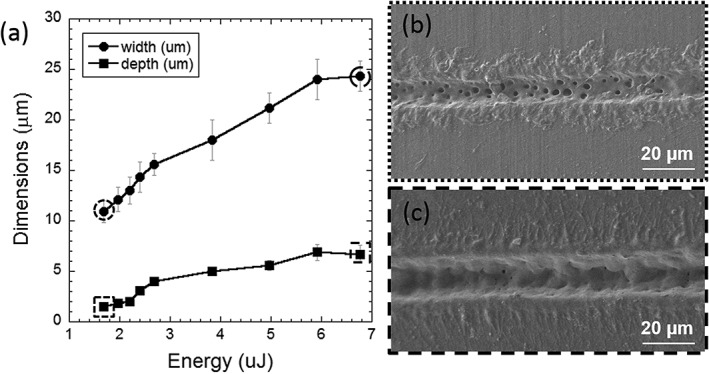
Groove width (circular dots) and depth (squared dots) as a function of the laser energy per pulse (a). SEM images of grooves obtained by laser ablation on PLLA‐PEG550 at low (b) and high energies (c). Groove dimensions at these energy levels are marked with dotted (low energy) and dashed (high energy) lines in (a).
The analysis of the effect of different surface microgrooves configuration on cell viability was carried out by modifying the geometrical dimensions and density of grooves. In a first trial (Configuration 1), the effect of the inter‐groove spacing (s) was analyzed by keeping constant the geometrical parameters w and d (w = 11 µm, d = 1.5 µm) and varying s from minimum distance of 5 µm, to a maximum distance of 20 µm (Figure 2). After in vitro tests on PLLA‐PEG550 samples following the Configuration 1, an optimal value of the inter‐groove spacing was determined and fixed for the second laser ablation trial (Configuration 2) where groove dimensions were changed as shown in Figure 3.
Figure 2.

SEM images of laser‐fabricated grooves on PLLA‐PEG550 varying the spacing between grooves (s) (Configuration 1): s = 5 µm (LSC1), s = 10 µm (LSC2), s = 15 µm (LSC3), and s = 20 µm (LSC4).
Figure 3.

SEM images of laser‐fabricated grooves on PLLA‐PEG550 varying the groove dimensions (w, d) (Configuration 2): w = 13 µm, d = 2 µm (LSC5), w = 15 µm, d = 4 µm (LSC6), w = 20 µm, d = 6 µm (LSC7), and w = 25 µm, d = 7 µm (LSC8).
Cyto‐ and hemocompatibility studies
In vitro cell culture analyses of the non‐patterned and patterned PLLA‐PEG550 surfaces described above were carried out with L929 cell line according to ISO 10993–530 to assess cytotoxicity and primary endothelial cells (HCMEC) in order to test endothelialization potential. In addition, hemocompatibility was analyzed by hemolysis testing, platelet adhesion assay and leucocyte activation test as described in the methods section.
Cytocompatibility analysis using L929 cell line
Basic cytocompatibility was assessed using a direct contact format and analyzing three different parameters in multiplex. L929 cell adhesion to the different surfaces was quantified using the cell viability measurement while in addition material toxicity and apoptosis induction were assessed. The multiplex assay results (Figure 4) demonstrate good cytocompatibility of all tested grooved surfaces. The cell viability measurement indicates the number of cells that adhered to the different surfaces. As can be seen in Figure 4 no difference in L929 cell adhesion was observed among PLLA‐PEG550 samples—patterned or not. All surfaces showed absolutely no cytotoxicity and no significantly elevated apoptosis induction compared to flat PLLA‐PEG550 control. Only LSC1 surface showed slightly but not significantly elevated apoptosis in comparison to TCPS. The data show that the polymer and the laser micropatterns are non‐toxic and did not present any other negative effect on cells in direct contact with the films. No significant differences in terms of viability, toxicity and apoptosis levels were observed when results were compared for PEG‐functionalized PLLA over neat PLLA controls (PL18 and PL38).
Figure 4.
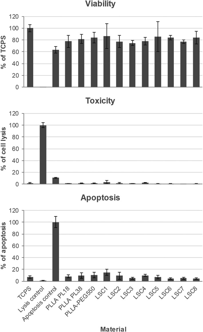
Multiplex assay results of viability, cytotoxicity, and apoptosis measurements using L929 cells seeded directly onto nonpatterned and laser‐patterned PLLA‐PEG550 surfaces and grown for 24 h. TCPS and neat PL18 and PL38 substrates were used as controls. Cell viability results are depicted in % compared to TCPS. Cytotoxicity was analyzed using lysed cells as positive control (100% of cell lysis). Apoptosis induction was measured using staurosporine induced cells as positive control (100% of apoptosis). N = 11, p values = 0.0045. Not significant difference was detected for each surface compared to TCPS.
Endothelial cell adhesion
Endothelial cell adhesion was assessed using primary HCMEC, which line the coronary microvasculature in vivo and therefore are better suited to represent the actual situation than commonly used HUVECs. Representative micrographs of HCMECs 24 hours after seeding onto the different substrates and stained using live/dead staining are depicted in Figure 5 and average cell numbers are given in Figure 6. Cell adhesion was greatly reduced on flat PLLA‐PEG550 and samples with laser configurations LSC1–4 to 20–40% when compared to the TCPS control of perfect cell adhesion and spreading (100%). However, we observed a gradual increase in number of healthy adherent cells on micropatterned samples of configurations LSC5–8 to up to 80% of adherent cells in LSC7 and LSC8 (Figure 6). While cells on flat PLLA‐PEG550 and LSC1–4 showed a rather round or slightly elongated morphology accompanied by little spreading and formation of cell clumps ECs on LSC5–8 exhibited more and more elongation and spreading with formation of appendices (Figure 5). Moreover, microgroove pattern configurations led to cell alignment, especially in case of LSC7 and LSC8 (LSC7: w = 20 µm, d = 6 µm, and LSC8: w = 25 µm, d = 7 µm), which was analyzed by measuring nucleus orientation angles (Figure 7) for these two laser configurations. In both patterns about 60% of the cells were oriented along the groove direction with a small deviation angle of ± 15°, while 85% of cells were oriented with a deviation angle of ± 30° with respect to the trend.
Figure 5.

Representative micrographs of HCMECs 24 h after seeding onto the nonpatterned and patterned PLLA‐PEG550 surfaces and stained using live/dead staining (green, living cells; red, nuclei of dead cells). Scale bar represents 100 µm.
Figure 6.

Average endothelial cell numbers on the different PLLA‐PEG550 surfaces. Grey‐scale corresponds to cell morphology (from dark, very good cell morphology; to light, poor morphology and spreading).
Figure 7.

Polar graphs showing the angle of orientation of the cell nuclei on the LSC7 and LSC8 PLLA‐PEG550 surfaces (two samples each). Each spot represents one cell nucleus. The dashed line represents the main trend observed for cell nucleus‐orientation angle.
Immunofluorescent staining was used to assess cytoskeleton appearance (F‐actin) and focal adhesion points (vinculin) of cells on flat PLLA‐PEG550 compared to LSC7 and LSC8 patterns (Figure 8). On unpatterned PLLA‐PEG550 HCMECs showed random spreading with the formation of rounded protrusions while F‐actin staining was most pronounced at cell edges and often appeared in ruffles and vinculin was mostly seen in the cytoplasm around the nucleus. Only few focal adhesion points with high vinculin presence could be observed around the edges. Cells on the patterned films (LSC 7 and LSC8) showed a clear elongation along the groove direction accompanied by many and sometimes quite long protrusions reaching into the grooves. F‐actin cytoskeleton was most prominent around cell rims and at protrusion sites while vinculin was more focused in adhesion plaques (lines of strong vinculin staining) on the underside of the endothelial cells.
Figure 8.

Immunofluorescent staining of HCMECs on the patterned PLLA‐PEG550 surfaces (LSC7 and LSC8) compared to the flat substrate. Enlarged sections are shown in lower panel. Vinculin is shown in green (Vinculin‐rich regions marked with V), F‐actin in red (F‐actin‐rich areas marked with A) and nuclei (DAPI) in blue. Scale bars correspond to 50 and 10 µm, respectively.
Hemocompatibility
Hemolysis testing is required for the evaluation of biomaterials intended for stent devices according to DIN EN ISO 10993–4.31 Figure 9(a) shows results from the hemolysis testing performed on the non‐patterned and patterned PLLA‐PEG550 surfaces using human whole blood (diluted) and PS as control. As can be seen in the figure, none of the surfaces induces hemolysis or blood toxicity (hemolysis ratios <2% corresponds to non‐hemolytic surface as described by van Oeveren32) The two best pattern configurations in terms of endothelial cell adhesion (LSC7 and LSC8) were selected to evaluate the inflammatory induction by measuring the leucocyte activation marker PMN elastase [Figure 9(b)]. The selected pattern configurations led to a slight but significant increase in PMN elastase expression compared to the non‐patterned PLLA‐PEG550 and the PS controls, although LSC7 to a lesser degree than LSC8.
Figure 9.

Hemolysis testing performed with all the PLLA‐PEG550 surfaces using human blood and polystyrene (PS) dishes as control. In lysis control blood lysis was induced by dilution in pure water instead of 0.9% NaCl (a). N = 9, p values = 0.0056. Not significant difference was detected compared to PS control. Leukocyte activation tested using PMN elastase levels from human blood incubated with non‐patterned and patterned (LSC7–8) PLLA‐PEG550 surfaces. 100 ng/mL lipopolysaccharides (LPS) from Escherichia coli were used to induce partial leucocyte activation (b). N = 3, p values = 0.0167. Both LSC7 and LSC8 show a significant increase compared to PS.
In addition, platelet adhesion to the selected materials was evaluated based on their morphology as an indicator of material thrombogenicity. Figure 10 shows exemplary micrographs of platelets adhered to patterned (LSC8) and non‐patterned PLLA‐PEG550 surfaces. While non‐patterned PLLA‐PEG550 had low platelet adhesion and spreading, the patterned surfaces showed increased platelet adhesion to the groove areas. Platelet morphology was more spread with some platelets aggregating on top of those spread platelets (categorization of platelet morphology was done according to Ko et al.33)
Figure 10.

Exemplary micrographs of human platelets on nonpatterned and patterned (LSC7 and LSC8) PLLA‐PEG550 surfaces in two magnifications. Platelet‐rich plasma was incubated on the materials for 1 h and adherent platelets were visualized using F‐actin staining. Scale bar represents 50 and 10 µm, respectively.
DISCUSSION
The PEG‐modified PLLA material (PLLA‐PEG550) which was designed to allow for enhanced control over the degradation profile (see details about the material in supplementary data Part I) did not show significant differences in its cytocompatibility with L929 cell line, compared to the medical grade PL18 and PL38 neat polymers which are currently used in today's bio‐resorbable stent manufacturing. Therefore, the new strategy developed by Vornia in collaboration with the University of Cambridge26 for tuning the degradation rate of PLLA by incorporating PEG in the chemical structure of the bulk has been achieved without causing an unwanted effect on the material cell compatibility. PLLA‐PEG materials will not be affected by the laser micropatterning, given that the effects produced by the laser on the material are limited to the topmost surface layer of the material (<10 nm) and no chemical or structural bulk properties are modified.34 In addition, since PLLA is a bulk eroding polymer,35 surface treatments should not have a major influence on the degradation rate of the material.
Laser ablation was applied successfully on PLLA‐PEG550 to generate grooves of good quality and precision, enabling a fast and swift variation of pattern geometry and density. Groove dimensions (width and depth) were dependent on the used laser pulse energy and therefore we could generate a range of different ridge and groove topographies. The resulting grooves were characterized by pore formation inside of the grooves for the entire range of energies considered, a phenomenon also described in a former report about picosecond pulsed laser ablation on medical grade PLLA.36 The pores showed an average diameter of approximately 2 micrometers.
The effect of these laser‐fabricated grooves on general cytocompatibility using L929 cell line was analyzed and we found that all the surfaces showed no cytotoxicity or apoptosis induction, without significant differences between non‐patterned and patterned PLLA‐PEG550 surfaces. These results indicate that the laser ablation technology is perfectly suited to produce cell adhesion substrates for medical implants. The adhesion of HCMECs was studied in more detail in order to evaluate the potential of different groove dimensions to promote cell attachment and orientation. We found that HCMEC adhesion and alignment were encouraged when ECs were seeded on the patterned surfaces with increased width and depth: HCMEC adhesion increased from approximately 20% (percentage adherent viable ECs with respect to that observed on standard TCPS), on the non‐patterned PLLA‐PEG550 surface, to 80% on the patterned surfaces with grooves 20–25 µm wide and 6–7 µm deep. The general trend settled in literature is that EC elongation and spreading are encouraged on grooved nanopatterns or low range‐micropatterns.9, 10, 12, 18, 37 The laser ablation technique applied for groove generation does not allow us to distinguish between the effects of groove width and depth separately on HCMEC adhesion and alignment, since an increase of the laser energy deposited in the material leads to the simultaneous increase of groove width and depth. However, from our results we can deduce that cell adhesion, elongation and alignment were clearly promoted when groove width and depth were increased from 15 and 4 micrometers, to values of 20 and 6 micrometers, respectively. Contrary to groove width and depth, the spacing between grooves seemed to have a minor influence on ECs alignment and adhesion since no significant differences were observed when the inter‐groove spacing was increased from 5 to 20 micrometers. According to the water contact angle measurements performed on non‐patterned and patterned (LSC8) PLLA‐PEG550 sheets, the surface gets more hydrophobic after the laser ablation process, with an increase of the contact angle from 71.1° ± 0.2° to 112° ± 1°. Since the PEG content improves the hydrophilic properties of pure PLLA,38 this change in the surface wettability could be related to the removal of PEG from the topmost surface layer of the material by laser ablation; however, since the PEG was incorporated in the chemical structure of PLLA and therefore homogenously distributed in the polymer, it is more likely that the observed increase of hydrophobicity after laser micropatterning is caused by the topographical surface modification. Improvement of cell adhesion is typically linked with hydrophilic surfaces; therefore, the observed improved cell adhesion on some of the patterns (LSC7 and LSC8) must be caused by the generated topography and not by the change on surface wettability.
The typical EC width is around 20–50 micrometers. Regarding the physical constraints that grooves entail for the cells, it is reasonable to think that cells would fit better with grooves of dimensions close to their size or slightly narrower or wider. Likewise, a larger depth would lead to a stronger confinement effect. According to Eskin et al.,39 the degree of endothelial cell alignment is closely related to the level of shear stress produced by the blood flow on the cell: this suggests that the confinement produced by the deepest grooves created a similar environment for the cells, as the blood flow does in vivo, leading to a high cell alignment. Immunofluorescence microscopy images shown in Figure 8 support also the similarities between the effect of the blood flow on endothelial cell adhesion and morphology in vivo 40 and the effect exerted by the grooves: endothelial cells adhered to the non‐patterned PLLA‐PEG550 surface looked flat with rounded protrusions, showing F‐actin mostly confined to the edges and vinculin uniformly distributed in the cytoplasm, indicating that they were scrambling to find anchoring points for focal adhesion. This can be explained by the presence of PEG chains on the surface of the PLLA‐PEG550 material which are known to form a cell repellent surface. On the contrary, endothelial cells attached to the patterned PLLA‐PEG550 appeared elongated and vinculin staining was prominent in long focal plaques and along the protrusions indicating that the cells find many anchoring points inside of the porous grooves and on top of the spacing.
Although all the surfaces analyzed were non‐hemolytic, laser patterning clearly led to increased platelet adhesion. This might be a result of the increased roughness of the grooves due to the presence of nanopores since platelets mainly adhered inside of the porous grooves and not onto the smoother inter‐groove spacing. In the literature, the dependence of platelet adhesion on surface roughness is discussed controversially with examples of increased and decreased platelet deposition upon roughening.41, 42, 43, 44, 45 In one of these studies41 it is suggested that platelet adhesion is increased on surfaces with roughness higher than platelet dimensions (approximately 2 µm) since the contact area for platelet adhesion is higher. This observation is in good agreement with our results. Spread platelets were found on patterned PLLA‐PEG550 surfaces, while platelets on the non‐patterned PLLA‐PEG550 surfaces showed a round morphology with minor flattening evident. In addition, patterning seemed to slightly increase leucocyte activation compared to the non‐patterned PLLA‐PEG550 substrate. So far, the mechanism of neutrophil activation by a material surface is not clearly defined in literature but surface chemistry and topography were shown to influence neutrophil behavior.46, 47
Together our results show that laser micro‐patterned surfaces are non‐toxic for a control cell line and for human cells (ECs and blood cells) and promote endothelialization in case of laser configurations with higher groove width and depth, and therefore show a high potential for cardiovascular applications. However, issues regarding platelet adhesion and spreading and leucocyte activation (related to inflammatory induction) should be addressed before applying this surface solution for promoting endothelialization on the inner surface of cardiovascular stents. Further experiments need to be performed to analyze endothelialization under conditions that simulate the in vivo environment, such as blood flow conditions. The simulation study performed by Pham et al.43 regarding blood flow dynamic suggests that, under flow conditions, platelet adhesion can be reduced on microstructured surfaces because of the micro shear gradient produced around the patterns. In vivo, a healthy endothelial cell layer is considered the best anti‐thrombogenic and anti‐inflammatory surface.5 Thus, the potential to promote fast endothelialization of a scaffold might overcome the slight increase in thrombogenicity due to platelet adhesion and inflammation due to leucocyte activation that we observed here.
Laser micropatterning technology can be successfully combined with polymer tubing extrusion processes via laser micromachining of the metallic mandrel (see details on Part III of the supplementary data). This allows overcoming two of the main challenges in transferring physical surface patterning technologies to clinical application, such as scalability and pattern precision.
CONCLUSIONS
Ultrashort pulsed laser technology has been applied on a PEG‐functionalized PLLA material to generate patterns able to promote HCMEC adhesion and elongation, emulating in some extent the effects that the blood flow has in vivo. Patterned surfaces were completely cyto‐compatible and increased endothelial cell adhesion threefold with respect to the non‐patterned surface. Although platelet adhesion was also observed to increase in the patterns, the results obtained at this respect are not conclusive and further experiments must be performed to investigate the balance between endothelial cell and platelet adhesion under blood flow conditions. The endothelialization promoter patterns have also been generated on a metallic extrusion mandrel proving laser technology (in combination with extrusion technologies) as a high potential method for manufacturing of advanced stents.
Supporting information
Supplementary materials
How to cite this article: Pacharra S, Ortiz R, McMahon S, Wang W, Viebahn R, Salber J, Quintana I. 2019. Surface patterning of a novel PEG‐functionalized poly‐l‐lactide polymer to improve its biocompatibility: Applications to bioresorbable vascular stents. J Biomed Mater Res Part B 2019:107B:624–634.
REFERENCES
- 1. Li AY, Law KB, Phillips KRB, Nwachukwu H, Butany J, Gotlieb AI. Pathology of cardiovascular interventions and surgery. Diagn Histopathol 2010;16(1):17–30. [Google Scholar]
- 2. Garg S, Serruys PW. Coronary stent: Current status. J Am Coll Cardiol 2010;56(10):S1–S42. [DOI] [PubMed] [Google Scholar]
- 3. Kipshidze N, Dangas G, Tsapenko M, Moses J, Leon MB, Kutryk M, Serruys P. Role of the endothelium in modulating neointimal formation: Vasculoprotective approaches to attenuate restenosis after percutaneous coronary interventions. J Am Coll Cardiol 2004;44(4):733–739. [DOI] [PubMed] [Google Scholar]
- 4. Liu T, Liu S, Zhang K, Chen J, Huang N. Endothelialization of implanted cardiovascular biomaterial surfaces: The development from in vitro to in vivo. J Biomed Mater Res A 2014;102(10):3754–3772. [DOI] [PubMed] [Google Scholar]
- 5. de Mel A, Jell G, Stevens MM, Seifalian AM. Biofunctionalization of biomaterials for accelerated in situ endothelialisation: A review. Biomacromolcules 2008;9(11):2969–2979. [DOI] [PubMed] [Google Scholar]
- 6. Bettinger CJ, Langer R, Borenstein T. Engineering substrate topography at the micro‐ and nanoscale to control cell function. Angew Chem Int Ed 2009;48:5406–5415. [DOI] [PMC free article] [PubMed] [Google Scholar]
- 7. Ross AM, Jiang Z, Bastmeyer M, Lahann J. Physical aspects of cell culture substrates: Topography, roughness, and elasticity. Small 2012;8(3):336–355. [DOI] [PubMed] [Google Scholar]
- 8. Nikkhah M, Edalat F, Manoucheri S, Khademhosseini A. Engineering microscale topographies to control the cell‐substrate interface. Biomaterials 2012;33:5230–5246. [DOI] [PMC free article] [PubMed] [Google Scholar]
- 9. Lu J, Rao MP, MacDonald NC, Khang D, Webster TJ. Improved endothelial cell adhesion and proliferation on patterned titanium surfaces with rationally designed micrometer to nanometer features. Acta Biomater 2008;4(1):192–201. [DOI] [PubMed] [Google Scholar]
- 10. Biela SA, Su Y, Spatz JP, Kemkemer R. Different sensitivity of human endothelial cells, smooth muscle cells, and fibroblasts to topography in the nano‐micro range. Acta Biomater 2009;5(7):2460–2466. [DOI] [PubMed] [Google Scholar]
- 11. Ranjan A, Webster TJ. Increased endothelial cell adhesion and elongation on micro‐patterned nano‐rough poly(dimethylsiloxane) films. Nanotechnology 2009;20(39):305102. [DOI] [PubMed] [Google Scholar]
- 12. Liliensiek SJ, Wood JA, Yong J, Auerbach R, Nealey PF, Murphy CJ. Modulation of human vascular endothelial cell behaviors by nanotopographic cues. Biomaterials 2010;31(20):5418–5426. [DOI] [PMC free article] [PubMed] [Google Scholar]
- 13. Zheng N, Yang P, Wang QY, Yang ZH, Huang N. Preparation of micro‐patterned surfaces of Si‐N‐O films and their influence on adhesion behavior of endothelial cells. Sci China Tech Sci 2010;53(1):257–263. [Google Scholar]
- 14. Franco D, Klingauf M, Bednarzik M, Cecchini M, Kurtcuoglu V, Gobrecht J, Poulikakos D, Ferrari A. Control of initial endothelial spreading by topographic activation of focal adhesion kinase. Soft Matter 2011;7:7313–7324. [Google Scholar]
- 15. Dickinson LE, Rand DR, Tsao J, Eberle W, Gerecht S. Endothelial cell responses to micropillar substrates if varying dimensions and stiffness. J Biomed Mater Res 2012;100A(6):1457–1466. [DOI] [PMC free article] [PubMed] [Google Scholar]
- 16. Aktas C, Dörrschuck E, Schuh C, Miró MM, Lee J, Pütz N, Wennemuth G, Metzger W, Oberringer M, Veith M, Abdul‐Khaliq H. Micro‐ and nanostructured Al2O3 surfaces for controlled vascular endothelial and smooth muscle cell adhesion and proliferation. Mater Sci Eng C 2012;32:1017–1024. [Google Scholar]
- 17. Franco D, Milde F, Klingauf M, Orsenigo F, Dejana E, Poulikakos D, Cecchini M, Koumoutsakos P, Ferrari A, Kurtcuoglu V. Accelerated endothelial wound healing on microstructured substrates under flow. Biomaterials 2013;34:1488–1497. [DOI] [PubMed] [Google Scholar]
- 18. Ding Y, Yang Z, Bi CWC, Yang M, Xu SL, Lu X, Huang N, Huang P, Leng Y. Directing vascular cell selectivity and hemocompatibility on patterned platforms featuring variable topographic geometry and size. ACS Appl Mater Interfaces 2014;6:12062–12070. [DOI] [PubMed] [Google Scholar]
- 19. Anderson D, Hinds M. Endothelial cell micropatterning: Methods, effects, and applications. Ann Biomed Eng 2011;39(9):2329–2345. [DOI] [PMC free article] [PubMed] [Google Scholar]
- 20. Chong DST, Lindsey B, Dalby MJ, Gadegaard N, Seifalian AM, Hamilton G. Luminal surface engineering, micro and nanopatterning: Potential for self endothelialising vascular grafts? Eur J Vasc Endovasc Surg 2014;47(5):566–576. [DOI] [PubMed] [Google Scholar]
- 21. Sprague EA, Tio F, Ahmed SH, Granada JF, Bailey. Impact of parallel micro‐engineered stent grooves on endothelial cell migration, proliferation, and function. Circ Casdiovasc Interv 2012;5(4):499–507. [DOI] [PubMed] [Google Scholar]
- 22. Liang C, Hu Y, Wang H. Biomimetic cardiovascular stents for in vivo re‐endothelialization. Biomaterials 2016;103:170–182. [DOI] [PubMed] [Google Scholar]
- 23. Cutiongco MFA, Goh SH, Aid‐Launais R, Le Visage C, Low HY, Yim EKF. Planar and tubular patterning of micro and nanotopographies on poly(vynil alcohol) hydrogel for improved endothelial cell responses. Biomaterials 2016;84:184–195. [DOI] [PubMed] [Google Scholar]
- 24.Textured silicone tubing for electrical pacing leads. US 6438425 B1.
- 25. Pang JH, Farhatnia Y, Godarzi F, Tan A, Rajadas J, Cousins BG, Seifalian AM. In situ endothelialization: Bioengineering considerations to translation. Small 2015;11(47):6248–6264. [DOI] [PubMed] [Google Scholar]
- 26. Azhari Z, McMahon S, Pierucci L, Wang W, Cameron RE. Short poly(ethylene glicol) block initiation of poly(l‐lactide) di‐block copolymers: A strategy for tuning the degradation of resorbable devices. Polym Int 2018. [Google Scholar]
- 27.ISO‐10993:2009. Biological evaluation of medical devices.
- 28. Wang J, He Y, Maitz MF, Collins B, Xiong K, Guo L, Yun Y, Wan G, Huang N. A surface‐eroding poly(1,3‐trimethylene carbonate) coating for fully biodegradable magnesium‐based stent applications: Toward better biofunction, biodegradation and biocompatibility. Acta Biomater 2013;9(10):8678–8689. [DOI] [PubMed] [Google Scholar]
- 29. Parnham MJ, Wetzig H. Toxicity screening of liposomes. Chem Phys Lipids 1993;64:263–274. [DOI] [PubMed] [Google Scholar]
- 30.Biological evaluation of medical devices. Part 5: Tests for cytotoxicity: In vitro methods. DIN EN ISO 10993 2009;5:1–7.
- 31.Biological evaluation of medical devices. Part 4: Selection of tests for interactions with blood. DIN EN ISO 10993 2009;4:1–41.
- 32. Van Oeveren W. Obstacles in haemocompatibility testing. Scientifica 2013;2013:392584. [DOI] [PMC free article] [PubMed] [Google Scholar]
- 33. Koh LB, Rodriguez I, Venkatraman SS. The effect of topography of polymer surfaces on platelet adhesion. Biomaterials 2010;31:1533–1545. [DOI] [PubMed] [Google Scholar]
- 34. Ortiz R, Moreno‐Flores S, Aurrekoetxea I, Quintana I, Vivanco MdM, Toca‐Herrera JL. High‐throughput laser generation of topological cues on a transparent polymeric biomaterial to anchor stem cells and control adipocyte morphology. Unpublished.
- 35. Burkersroda FV. Schedl L, and Göpferich A. Why degradable polymers undergo surface or bulk erosion. Biomaterials 2002;23:4221–4231. [DOI] [PubMed] [Google Scholar]
- 36. Ortiz R, Quintana I, Etxarri J, Lejardi A, Sarasua J‐R. Picosecond laser ablation of poly‐L‐lactide: Effect of crystallinity on the material response. J Appl Phys 2011;110:094902. [Google Scholar]
- 37. Vandrangi P, Gott SC, Kozaka R, Rodgers VGJ, Rao MP. Comparative endothelial cell response on topographically patterned titanium and silicon substrates with micrometers to sub‐micrometer feature sizes. PLoS One 2014;9(10):e111465. [DOI] [PMC free article] [PubMed] [Google Scholar]
- 38. Athanasoulia IG, Tarantili PA. Preparation and characterization of polyethylene glycol/poly(L‐lactic acid) blends. Pure Appl Chem 2016;89(1):141–152. [Google Scholar]
- 39. Eskin SG, Ives CL, McIntire LV, Navarro LT. Response of cultured endothelial cells to steady flow. Microvasc Res 1984;28:87–94. [DOI] [PubMed] [Google Scholar]
- 40. Cucina A, Sterpetti AV, Pupelis G, Fragale A, Lepidi S, Cavallaro A, Giustiniani Q, D'Angelo LS. Shear stress induces changes in the morphology and cytoskeleton organisation of arterial endothelial cells. Eur J Vasc Endovasc Surg 1995;9(1):86–92. [DOI] [PubMed] [Google Scholar]
- 41. Chen L, Han D, Jiang L. On improving blood compatibility: From bioinspired to synthetic design and fabrication of biointerfacial topography at micro/nano scales. Colloids Surf B 2011;85(1):2–7. [DOI] [PubMed] [Google Scholar]
- 42. Lu J, Yao C, Yang L, Webster TJ. Decreased platelet adhesion and enhanced endothelial cell functions on nano and submicron‐rough titanium stents. Tissue Eng Part A 2012;18:13–14. [DOI] [PubMed] [Google Scholar]
- 43. Pham TT, Wiedemeier S, Maenz S, Gastrock G, Settmacher U, Jandt KD, Zanow J, Lüdecke C, Bossert J. Hemodynamic aspects of reduced platelet adhesion on bioinspired microstructured surfaces. Colloid Surf B 2016;145:502–509. [DOI] [PubMed] [Google Scholar]
- 44. Ye X, Shao Y‐L, Zhou M, Li J, Cai L. Research on microstructure and hemocompatibility of the artificial heart valve surface. Appl Surf Sci 2009;255:6686–6690. [Google Scholar]
- 45. Ko TM, Jui‐Che L, Cooper SL. Surface characterization and platelet adhesion studies of plasma‐sulphonated polyethylene. Biomaterials 1993;14(9):657–664. [DOI] [PubMed] [Google Scholar]
- 46. Tan J, Shen H, Carter KL, Saltzman WM. Controlling human polymorphonuclear leukocytes motility using microfabrication technology. J Biomed Mater Res 2000;51(4):694–702. [DOI] [PubMed] [Google Scholar]
- 47. Patel JD, Krupka T, Anderson JM. iNOS‐mediated generation of reactive oxygen and nitrogen species by biomaterial‐adherent neutrophils. J Biomed Mater Res 2007;80A(2):381–390. [DOI] [PubMed] [Google Scholar]
Associated Data
This section collects any data citations, data availability statements, or supplementary materials included in this article.
Supplementary Materials
Supplementary materials