Abstract
Zirconia‐based restorations are showing an increase as the clinicians’ preferred choice at posterior sites because of the strength and esthetic properties of such restorations. However, all‐ceramic restorations fracture at higher rates than do metal‐based restorations. Margin design is one of several factors that can affect the fracture strength of all‐ceramic restorations. The aim of this study was to assess the effect of preparation and crown margin design on fracture resistance. Four groups of bilayer zirconia crowns (with 10 crowns in each group) were produced by hard‐ or soft‐machining technique, with the following four different margin designs: chamfer preparation (control); slice preparation; slice preparation with an additional cervical collar of 0.7 mm thickness; and reduced occlusal thickness (to 0.4 mm) on slice preparation with an additional cervical collar of 0.7 mm thickness. Additionally, 10 hard‐machined crowns with slice preparation were veneered and glazed with feldspathic porcelain. In total, 90 crowns were loaded centrally in the occlusal fossa until fracture. The load at fracture was higher than clinically relevant mastication loads for all preparation and margin designs. The crowns on a chamfer preparation fractured at higher loads compared with crowns on a slice preparation. An additional cervical collar increased load at fracture for hard‐machined crowns.
Keywords: dental ceramics dental restorations, monolithic, prosthondontics, tooth preparation
All‐ceramic dental restorations are increasingly preferred over metal‐based restorations 1, 2. The early all‐ceramic crowns had lower mechanical strength, which limited their use to the anterior region 1, 2. Polycrystalline ceramics, such as zirconia containing only crystalline particles, allow use of all‐ceramic restorations even at posterior teeth 3, 4. In order to improve the esthetics of zirconia, the crowns can be produced as bilayer crowns with an esthetic veneering layer over the zirconia core. However, the rate of failure of bilayer crowns is still higher than for metal‐based crowns 4, 5, 6, 7, 8, 9. The most frequent clinical failures are chipping and delamination of the veneering layer. Core fractures represent a low percentage of the failures observed in zirconia‐based bilayers in clinical studies 4. The amount of core fractures may, however, be underestimated because of the lack of a sufficient number of clinical studies with an observation period extending beyond 3 yr. Personal communication with dental technicians and practicing dentists indicate that core failure is more common than the scientific evidence indicates. Core fracture can be related to several factors, such as material composition, production method, design, and thickness of the core.
In vitro studies have been performed in order to achieve a better insight into the behavior of modern high‐strength zirconia crowns 10, 11. The fracture modes observed with conventional in vitro fracture strength tests often differ from the fracture modes observed with clinically failed zirconia‐based bilayer crowns 11, 12, 13. Differences between clinical observations and in vitro tests are evident in both fracture strength values and crack initiation sites, as well as in crack propagation patterns 14, 15, 16, 17. The fracture pattern of crowns fractured during clinical use demonstrates fracture origins in the cervical margin of the crown 15, 18, 19, 20 or from the intaglio surface of the crown 21, 22, 23 (Fig. 1). Margin failures often occur at the proximal area of the crown, where the finish line curves toward the occlusal surface over the gingival papilla 24.
Figure 1.
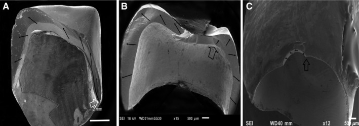
Three different fracture modes have been observed with zirconia‐based crowns fractured in clinical use (ongoing retrieval study). (A) Total fracture in two to three pieces, usually originating in the proximal margin area. (B) Total fracture in three pieces or more, with the fracture originating in the intaglio occlusal wall in a thin region of the crown. (C) Margin chip, usually observed on buccal or lingual flange. Open arrows indicate fracture origin. Black arrows indicate direction of crack propagation.
Margin failures may be related to the design and thickness of the crown margins. Multiple studies have been performed in order to evaluate the effect of margin design on load at fracture, but the results are inconclusive. Several studies find that the margin design has an effect on the fracture resistance 24, 25, 26, 27, 28, 29, while others see no such effect 30, 31. The large differences in study design among these trials complicate comparison and conclusions on this issue. Clinical recommendations for margin design are based on previous experiences with all‐ceramic crowns and also on the design of metal‐based crowns. It is not evident whether these recommendations are optimal for the modern high‐strength zirconia restorations. Most manufacturers of dental ceramics advise dentists to remove up to 0.5–1.5 mm of tooth substance to make room for a bilayer ceramic crown. A preparation depth of 1.5 mm increases the risk of negative effects on tooth vitality 32, 33. Based on mechanical properties, zirconia crowns can probably be made using a minimal invasive slice preparation technique, as suggested by some manufacturers and in scientific papers 34, 35. However, it is still uncertain which design provides optimal balance between crown strength and tooth vitality.
The aim of this study was to analyze the effect of different preparation and crown margin designs on load at fracture for bilayer zirconia crowns.
Material and methods
Crown preparation and margin designs
Two artificial models of premolar teeth were prepared for all‐ceramic crowns with an axial wall taper of 10 degrees and rounded edges. Two different finish line designs were prepared. One model had a circumferential chamfer preparation of 0.5 mm depth; the other had a circumferential slice preparation (Fig. 2).
Figure 2.
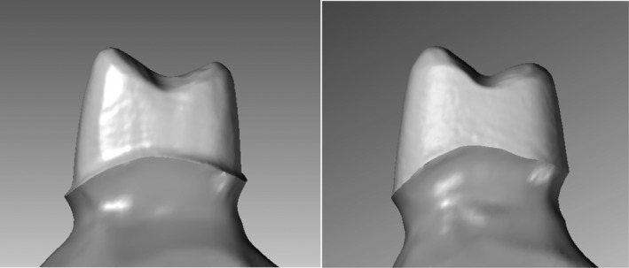
Two different types of preparations used in the test (lateral view).
Impressions of each preparation were taken using an A‐silicone impression material (Affinis; Coltene, Altsätten, Switzerland), and stone models of the preparation were scanned. The three‐dimensional (3D) digital files were used for designing the cores (Fig. 3A–C). The cores were designed and produced by a dental technician according to the protocol. Four different designs were made: uniform‐thickness (0.5 mm) crowns on the chamfer preparation [control (C)]; uniform‐thickness (0.5 mm) crowns on the slice preparation (S); uniform‐thickness (0.5 mm) crowns on the slice preparation with an additional 0.8 mm high cervical collar in the mesiolingual‐distal region (S + Col); and finally, reduced occlusal thickness (to 0.4 mm) crowns on the slice preparation with a 0.8 mm high cervical collar (S + Colr) (Fig. 3D).
Figure 3.
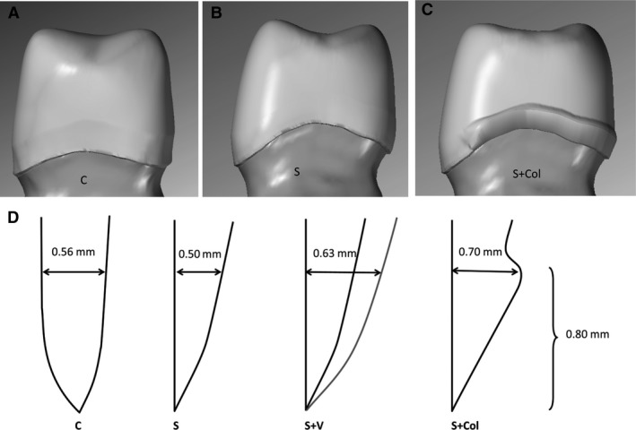
Three different margin designs (lateral view): chamfer preparation with uniform thickness (control) (A); slice preparation with a partial cervical collar (B); and slice preparation with a uniform thickness (0.5 mm) (C). In addition, one set of 10 crowns identical to those in panel B were made with reduced occlusal thickness (0.4 mm). (D) Measurements of the wall thickness of the four margin designs are shown (in cross section). The thickness is measured at the same height as the upper limit of the cervical collar. The different designs are chamfer (C), slice (S), slice with veneering layer (S + V), and slice with cervical collar (S + Col).
Ten crowns of each material were manufactured for each of the four designs according to instructions from the manufacturers. One set of 40 crowns was produced using a soft‐machining technique (SM) (Zerion HSC zirconium oxide ceramic single unit; Institut Straumann, Basel, Switzerland) and another set of 40 crowns was produced, with the same specifications, using a hard‐machining technique (HM) (Denzir Y‐TZP; Denzir Cad.esthetics, Skellefteå, Sweden). In addition, 10 HM crowns made for the slice preparation were veneered and glazed with feldspathic porcelain (S + V) (Fig. 4).
Figure 4.
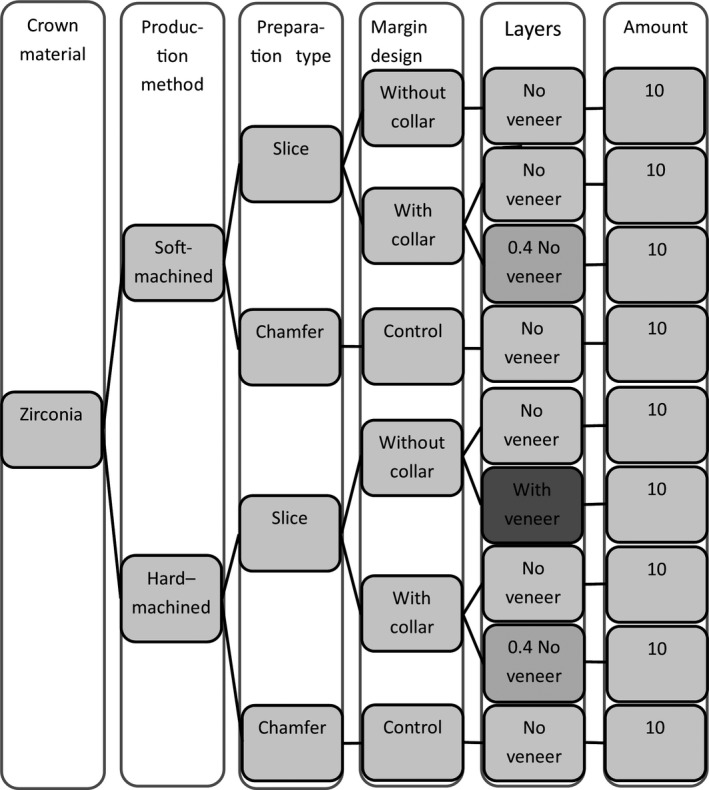
Flow chart of the crown production. The veneered crowns are indicated with darker shadow.
The cusps were designed with equal heights and aligned to prevent the crowns from tilting backwards during loading. The central fossa was designed to be rounded and shallow on the occlusal surface to increase the contact area between the crown and the indenter in order to disperse the load evenly and avoid localized contact damage.
Precementation examinations of margin defects
The crowns were examined at 10× magnification in an optical stereomicroscope (Leica M205 C; Leica Microsystems, Wetzlar, Germany) for signs of marginal defects. All defects or irregularities were registered and graded on a scale of 1–5, according to severity, on a Likert scale, as follows: 1, optimal margins without flaws; 2, minor chips and flaws; 3, multiple chips and flaws; 4, continuous flaws or uneven margins; and 5, large defects visible without a microscope 36. The SM crowns were manually adjusted externally at the margin after delivery from the technician to achieve an acceptable marginal thickness edge equivalent with the margins of the HM crowns. The margin adjustment was performed using a dental handpiece (KaVo K‐Control; Kavo, Biberach an den Riss, Germany) according to the manufacturer's recommendations. The crowns were re‐examined to ensure that no defects had occurred during the adjustments.
Load testing
The crowns were cemented to epoxy models (EpoFix; Struers, Ballerup, Denmark) of the preparations with zinc phosphate oxide cement (De Trey Zink; Dentsply DeTrey, Konstanz, Germany). The cement was chosen to minimize the bonding effect of the cement. Excess cement was removed, and after a 5‐min setting time the crowns were placed in distilled water at 37°C for 24 (range ± 2) h. The crowns were subsequently loaded centrally at the occlusal fossa with a horizontal cylindrical steel indenter of 13 mm in diameter, cushioned with a 2‐mm‐thick ethylene propylene diene rubber disc of hardness 90 Shore A (EPDM 90) to avoid contact damage. The cylinder was placed centrally to ensure even distribution of load between the cusps. The load was applied in a servo hydraulic testing system at 0.5 mm min−1 until fracture occurred (MTS 852 MiniBionix II; MTS Systems, Eden Prairie, MN, USA). The procedures were performed while the crowns were immersed in water at room temperature. Load at fracture was recorded. At 3,300 N, the procedure was halted because of equipment limitation. The fractured crowns were analyzed, using fractographic methods, to identify the fracture origin and direction of crack propagation 16, 37. The fracture initiation area was compared with the crown margins before fracture, to assess whether pre‐existing defects were the fracture initiators or not.
Statistical analysis
As a result of the limited number of specimens in each group and a tendency for skewed data, non‐parametric methods were used to analyze the results. The Kruskal–Wallis test was used for overall comparison and the Mann–Whitney U‐test was used for between‐group testing, with correction for multiple groups. Assessment of correlations was performed using Spearman's rank test. Significance was set to α = 0.05.
Results
After the loading test, 11 of 90 crowns did not fracture, mainly in the control groups with a chamfer preparation design (Figs 5 and 6, Table 1). Their load value was set to 3,300 N. Overall comparison of all data shows significant differences among the nine test groups (P = 0.0001).
Figure 5.
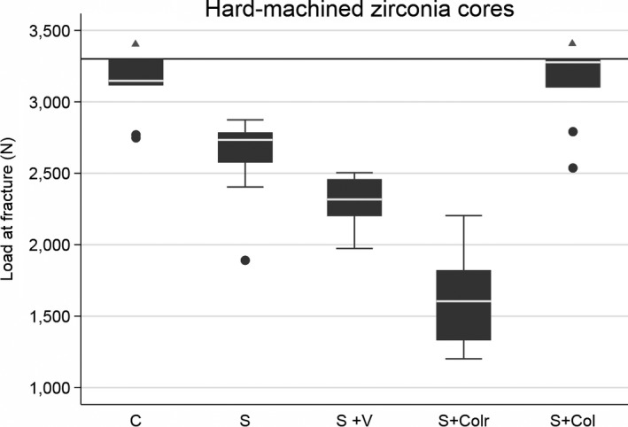
Box plot of the five hard‐machined groups with different margin designs. Further load was stopped at 3,300 N (horizontal reference line at y‐axis) as a result of equipment limitation. The line within boxes represents the median, and the bottom and top of boxes represent the first and third quartiles, respectively. The maximum and minimum whiskers represent 1.5 interquartile ranges. There were statistically significant differences among all the groups, except for comparison between the chamfer (C) group and the slice with cervical collar (S + Col) group (shown with triangles). S, slice; S + Colr, slice with collar and reduced occlusal thickness.
Figure 6.
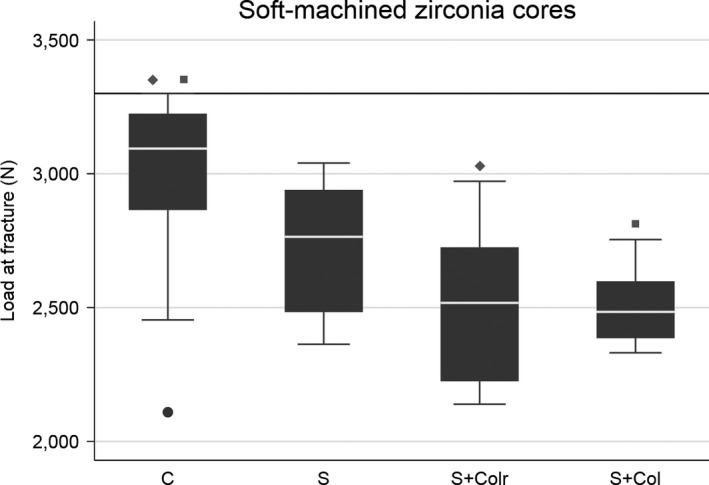
Box plot of the four soft‐machined groups with different margin designs. Further load was stopped at 3,300 N (horizontal reference line at y‐axis) as a result of equipment limitation. The line within boxes represents the median, and the bottom and top of boxes represent the first and third quartiles, respectively. The maximum and minimum whiskers represent 1.5 interquartile ranges. Statistically significant differences between groups are marked with corresponding squares or diamonds. C, chamfer; S, slice; S + Colr, slice with cervical collar and reduced occlusal thickness; S + Col, slice with cervical collar.
Table 1.
Overview of the fracture origin and margin quality evaluation
| Production method | Margin designs | Fracture origin | Margin defect mean value | ||
|---|---|---|---|---|---|
| Cervical | Intaglio occlusal surface | Non‐fractured crowns | |||
| Hard‐machined | Chamfer (control) | 5 | – | 5 | 1.6 |
| Slice with cervical collar | 6 | 3 | 1 | 2.8 | |
| Slice with cervical collar and reduced occlusal thickness | – | 10 | – | 3.2 | |
| Slice no collar | 1 | 8 | 1 | 1.5 | |
| Slice with collar and veneering | 7 | 2 | 1 | 2 | |
| Soft‐machined | Chamfer (control) | – | 7 | 3 | 2.5 |
| Slice with cervical collar | – | 10 | – | 2.6 | |
| Slice with cervical collar and reduced occlusal thickness | 1 | 9 | – | 2.9 | |
| Slice no collar | 2 | 8 | – | 3 | |
| Total | 22 | 57 | 11 | ||
In the HM groups, there were significant differences between all groups except between the control group (chamfer) and the group with a cervical collar of standard occlusal thickness. By contrast, in the SM groups, there were no significant differences except between the control group (chamfer) and the two groups with a cervical collar for both types of occlusal thicknesses.
Fractographic analysis revealed that no crowns fractured because of contact damage between the indenter and the crowns, as detected by light microscopy. Crowns fractured either from the crown margin (n = 22, Figs 7 and 8) or from the intaglio surface of the crown (n = 57, Fig. 9). Most crowns fractured into two or three pieces. Twenty‐four of 90 crowns fractured into four or five pieces.
Figure 7.
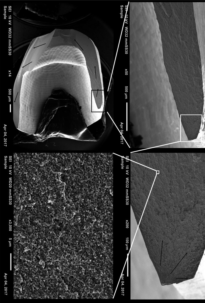
Fractographic map of a non‐veneered soft‐machined crown with slice preparation without a cervical collar. Black arrows show direction of crack propagation originating at the cervical edge of the crown.
Figure 8.
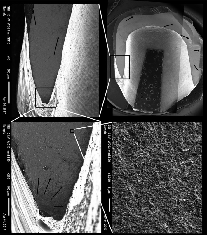
Fractographic map of a veneered hard‐machined crown with slice preparation without a cervical collar. Black arrows show direction of crack propagation originating at the cervical edge of the crown.
Figure 9.
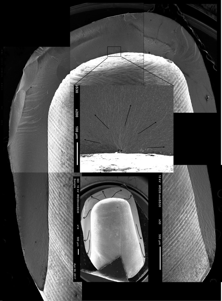
Fractographic map of a non‐veneered hard‐machined crown with slice preparation without a cervical collar. Blue arrows show direction of crack propagation originating at the intaglio occlusal surface of the crown.
There was no statistically significant correlation between fracture mode and load at fracture overall (r = 0.26) or within groups (r = 0.39 for HM groups and r = 0.04 for SM groups). There was no statistically significant correlation between margin defects and load at fracture (r = 0.25).
Discussion
The overall results indicate that preparation design, crown design, and manufacturing method affect load at fracture. The different design variables assessed in this study are not independent. An alteration in one of the design variables also causes change in other variables. Furthermore, the effect of each variable differed between the two materials tested. Nonetheless, some effects of the different variables can be isolated.
The finding that the chamfer design crowns fractured at a higher load than did the slice design crowns in both production‐method groups indicates that the commonly recommended chamfer margin design gives the strongest crowns. This is in accordance with previous studies 12, 27, 38, 39, 40, 41, 42, 43, 44. The increased thickness in the crown margin probably explains this result. Thick crown walls can, however, compromise tooth vitality by requiring increased drilling depth 33, 45, 46. The finding that all crowns fractured at a higher level than maximal mastication forces indicates that slice preparation design might result in sufficiently strong crowns 47. Further studies must be performed to evaluate this in a clinical setting.
The increased margin thickness in the collar resulted in an increase of almost 20% in load at fracture compared with uniform thickness slice preparation for the HM group. This is in accordance with previous findings 48, 49, 50. The additional collar results in fracture loads equal to the crowns made for the chamfer design. However, another study did not find a strengthening effect of a cervical collar similar to the results for the SM group in the present study 51. Slice preparation may be associated with biological benefits as it requires less removal of sound tooth substance. On the other hand, an over‐contoured crown margin may compromise gingival and periodontal health 52. Thus, a highly polished zirconia margin with no veneer may be less plaque retentive than a zirconia core veneered down to the crown margins because the latter will be bulkier. These findings indicate that a slice preparation with a modified crown design may increase both technical and biological success.
Reducing the occlusal thickness resulted in weaker crowns as expected based on previous studies (27, 40, 41, 42, 43, 47). This was, however, only statistically significant for the HM group. The results indicate that a change in occlusal thickness may have a greater effect on the load at fracture values than cervical thickness. The veneered crowns fractured at statistically significantly lower loads than the identical non‐veneered crowns. This indicates that post‐treatment of zirconia cores adversely affects fracture strength 53, 54. Only one HM group was veneered in this study; further studies are needed to assess the effect also on other zirconia cores.
Based on previous studies, a larger difference in load at fracture between HM and SM crowns had been expected 36. Our findings cannot fully explain why this is not the case in the present study. The results indicate that different margin designs have a more pronounced effect on the fracture resistance in HM zirconia cores for bilayer all‐ceramic crowns than in SM zirconia cores. This difference may be a result of microscopic‐level changes in the zirconia material occurring during the production by the two different methods. A final sintering of the SM zirconia may have a reducing effect on the microscopic defects that may have occurred during milling. Furthermore, the post‐sintering adjustment necessary on the margins of the SM crowns to achieve optimal fit and crown emergence profile can affect fracture resistance. The SM restorations are milled with slightly over‐contoured margins in the computer‐aided design/computer‐aided manufacturing (CAD/CAM) unit in order to reduce the risk of margin chips. Manual adjustment of the margins could theoretically have had a reinforcing effect on the core by introducing a t‐m phase transformation toughening effect at the molecular level. On the other hand, post sintering margin adjustment of the SM crowns can also introduce new defects, although none was observed in this study. The finding that only three crowns had fracture origins in pre‐existing defects indicates that margin flaws are not very detrimental to crown strength. It can, however, not be excluded that pre‐existing defects not detectable by light microscopy may contribute to crack initiation 18. Further studies of the effect of margin quality are needed to assess this.
The difference in fracture modes among the test groups indicates that both different production methods and designs affect fracture initiation and crack propagation. All fractured crowns in the present study fractured either from the margin or at the intaglio surface, as have been previously reported to be clinically relevant fracture patterns. The rubber disc placed between the indenter and the zirconia cores during loading prevented visible contact damage. It is reasonable to expect, however, that some contact damage has occurred at a microscopic level, although the effect of this is not obvious in the present study. The finding that more than two‐thirds of the crowns fractured from the intaglio occlusal surface indicates that occlusal thickness is also important for crown survival. This is in accordance with previous studies in which thinner walls resulted in weaker crowns 41, 44, 55. The finding that the crowns with reduced occlusal thickness had lower fracture loads further supports this point. The loading test configuration may explain the large proportion of fractures originating in the occlusal intaglio surface. The cylindrical indenter used to load the bicuspid zirconia cores may have created a wedging effect in addition to the axial load. Furthermore, the cement layer immediately beneath the loading area may have been crushed during loading, resulting in a local failure of the support of the zirconia core and leading to tensile stress and subsequent cracks at the intaglio surface. The cement used in this study was chosen in order to study zirconia cores without adhesive effects from the cement. This could produce somewhat different results from clinical situations and with other cements. The failure mode is, however, similar to clinical failures observed in an ongoing retrieval study, as seen in Fig. 1.
Previous studies reveal that alterations in margins design affect the cervical stress distribution 38, 49. The lowest load at fracture was 1,202 N, which is higher than the maximally measured biting force of 800–1,000 N 56. Considering the fact that the crowns in this study were not subjected to aging prior to testing and that they were produced and cemented under optimal conditions, the results can, nevertheless, be considered clinically relevant and indicate that zirconia‐based crowns can fracture during normal mastication forces if the design is poor or if there is a defect in a tensile stress location.
Within the limitations of this study, it can be concluded that zirconia crowns made for a chamfer preparation fracture at significantly higher loads than similar crowns made for a slice preparation design. Both preparation designs resulted in crowns that fractured at loads above normal mastication forces. A slice preparation with a modified cervical collar crown design may increase both technical and biological success. The veneering process decreases the fracture resistance significantly, just as reduced wall thickness reduces load at fracture.
Conflict of interests
The authors declare no conflict of interests..
Acknowledgements
The authors thank Professor Stein Atle Lie for statistical advice and professor Nils Roar Gjerdet for scientific advice. The study was funded by a scholarship from The Medical Faculty, University of Bergen.
Skjold A, Schriwer C, Øilo M. Effect of margin design on fracture load of zirconia crowns. Eur J Oral Sci 2019; 127: 89–96. © 2018 The Authors. Eur J Oral Sci published by John Wiley & Sons Ltd
References
- 1. Zhang Y, Kelly JR. Dental ceramics for restoration and metal veneering. Dent Clin North Am 2017; 61: 797–819. [DOI] [PMC free article] [PubMed] [Google Scholar]
- 2. Chen YW, Moussi J, Drury JL, Wataha JC. Zirconia in biomedical applications. Expert Rev Med Devices 2016; 13: 945–963. [DOI] [PubMed] [Google Scholar]
- 3. Alfawaz Y. Zirconia crown as single unit tooth restoration: a literature review. J Contemp Dent Pract 2016; 17: 418–422. [DOI] [PubMed] [Google Scholar]
- 4. Sailer I, Makarov NA, Thoma DS, Zwahlen M, Pjetursson BE. All‐ceramic or metal‐ceramic tooth‐supported fixed dental prostheses (FDPs)? A systematic review of the survival and complication rates. Part I: Single crowns (SCs) Dent Mater 2015; 31: 603–623. [DOI] [PubMed] [Google Scholar]
- 5. Wang X, Fan D, Swain MV, Zhao K. A systematic review of all‐ceramic crowns: clinical fracture rates in relation to restored tooth type. Int J Prosthodont 2012; 25: 441–450. [PubMed] [Google Scholar]
- 6. Triwatana P, Nagaviroj N, Tulapornchai C. Clinical performance and failures of zirconia‐based fixed partial dentures: a review literature. J Adv Prosthodont 2012; 4: 76–83. [DOI] [PMC free article] [PubMed] [Google Scholar]
- 7. Raigrodski AJ, Hillstead MB, Meng GK, Chung K‐H. Survival and complications of zirconia‐based fixed dental prostheses: a systematic review. J Prosthet Dent 2012; 107: 170–177. [DOI] [PubMed] [Google Scholar]
- 8. Pjetursson BE, Sailer I, Makarov NA, Zwahlen M, Thoma DS. All‐ceramic or metal‐ceramic tooth‐supported fixed dental prostheses (FDPs)? A systematic review of the survival and complication rates. Part II: Multiple‐unit FDPs. Dent Mater 2015; 31: 624–639. [DOI] [PubMed] [Google Scholar]
- 9. Larsson C, Wennerberg A. The clinical success of zirconia‐based crowns: a systematic review. Int J Prosthodont 2014; 27: 33–43. [DOI] [PubMed] [Google Scholar]
- 10. Nakamura K, Ankyu S, Nilsson F, Kanno T, Niwano Y, Vult von Steyern P, Örtengren U. Critical considerations on load‐to‐failure test for monolithic zirconia molar crowns. J Mech Behav Biomed Mater 2018; 87: 180–189. [DOI] [PubMed] [Google Scholar]
- 11. Kelly JR, Benetti P, Rungruanganunt P, Bona AD. The slippery slope: critical perspectives on in vitro research methodologies. Dent Mater 2012; 28: 41–51. [DOI] [PubMed] [Google Scholar]
- 12. Kim JH, Park JH, Park YB, Moon HS. Fracture load of zirconia crowns according to the thickness and marginal design of coping. J Prosthet Dent 2012; 108: 96–101. [DOI] [PubMed] [Google Scholar]
- 13. Sakaguchi R, Powers J. Craig's restorative dental materials. Philadelphia: Elsevier, 2012. [Google Scholar]
- 14. Øilo M, Kvam K, Tibballs JE, Gjerdet NR. Clinically relevant fracture testing of all‐ceramic crowns. Dent Mater 2013; 29: 815–823. [DOI] [PubMed] [Google Scholar]
- 15. Scherrer SS, Quinn GD, Quinn JB. Fractographic failure analysis of a Procera® All Ceram crown using stereo and scanning electron microscopy. Dent Mater 2008; 24: 1107–1113. [DOI] [PMC free article] [PubMed] [Google Scholar]
- 16. Scherrer SS, Lohbauer U, Della Bona A, Vichi A, Tholey MJ, Kelly JR, van Noort R, Cesar PF. ADM guidance‐ceramics: guidance to the use of fractography in failure analysis of brittle materials. Dent Mater 2017; 33: 599–620. [DOI] [PubMed] [Google Scholar]
- 17. Lawn B, Bhowmick S, Bush MB, Qasim T, Rekow ED, Zhang Y. Failure modes in ceramic‐based layer structures: a basis for materials design of dental crowns. J Am Ceram Soc 2007; 90: 1671–1683. [Google Scholar]
- 18. Øilo M, Quinn GD. Fracture origins in twenty‐two dental alumina crowns. J Mech Behav Biomedl Mater 2016; 53: 93–103. [DOI] [PubMed] [Google Scholar]
- 19. Øilo M, Gjerdet NR. Fractographic analysis of all‐ceramic crowns: a study of 27 clinically‐fractured crowns. Dent Mater 2013; 29: e78–e84. [DOI] [PubMed] [Google Scholar]
- 20. Scherrer SS, Quinn JB, Quinn GD, Kelly JR. Failure analysis of ceramic clinical cases using qualitative fractography. Int J Prosthodont 2006; 19: 185–192. [PubMed] [Google Scholar]
- 21. Kelly JR. Clinically relevant approach to failure testing of all‐ceramic restorations. J Prosthet Dent 1999; 81: 652–661. [DOI] [PubMed] [Google Scholar]
- 22. Kelly JR, Giordano R, Pober R, Cima MJ. Fracture surface analysis of dental ceramics: clinically failed restorations. Int J Prosthodont 1990; 3: 430–440. [PubMed] [Google Scholar]
- 23. Thompson JY, Anusavice KJ, Naman A, Morris HF. Fracture surface characterization of clinically failed all‐ceramic crowns. J Dent Res 1994; 73: 1824–1832. [DOI] [PubMed] [Google Scholar]
- 24. Øilo M, Kvam K, Reisegg K, Gjerdet N. The effects of margin curvature on load at fracture of ceramic crowns. Int J Prosthodont 2015; 28: 357–359. [DOI] [PubMed] [Google Scholar]
- 25. Reich S, Petschelt A, Lohbauer U. The effect of finish line preparation and layer thickness on the failure load and fractography of ZrO2 copings. J Prosthet Dent 2008; 99: 369–376. [DOI] [PubMed] [Google Scholar]
- 26. Jalalian E, Aletaha NS. The effect of two marginal designs (chamfer and shoulder) on the fracture resistance of all ceramic restorations, Inceram: an in vitro study. J Prosthodont Res 2011; 55: 121–125. [DOI] [PubMed] [Google Scholar]
- 27. Jalalian E, Rostami R, Atashkar B. Comparison of chamfer and deep chamfer preparation designs on the fracture resistance of zirconia core restorations. J Dent Res Dent Clin Dent Prospects 2011; 5: 41–45. [DOI] [PMC free article] [PubMed] [Google Scholar]
- 28. Whitton A, Qasim T, Ford C, Hu XZ, Bush M. The role of skirt geometry of dental crowns on the mechanics of failure: experimental and numerical study. Med Eng Phys 2008; 30: 661–668. [DOI] [PubMed] [Google Scholar]
- 29. Rekow ED, Zhang G, Thompson V, Kim JW, Coehlo P, Zhang Y. Effects of geometry on fracture initiation and propagation in all‐ceramic crowns. J Biomed Mater Res B Appl Biomater 2009; 88: 436–446. [DOI] [PubMed] [Google Scholar]
- 30. Aboushelib MN. Fatigue and fracture resistance of zirconia crowns prepared with different finish line designs. J Prosthodont 2012; 21: 22–27. [DOI] [PubMed] [Google Scholar]
- 31. Cortellini D, Canale A, Souza ROA, Campos F, Lima JC, Özcan M. Durability and weibull characteristics of lithium disilicate crowns bonded on abutments with knife‐edge and large chamfer finish lines after cyclic loading. J Prosthodont 2015; 24: 615–619. [DOI] [PubMed] [Google Scholar]
- 32. Murray PE, Smith AJ, Windsor LJ, Mjor IA. Remaining dentine thickness and human pulp responses. Int Endod J 2003; 36: 33–43. [DOI] [PubMed] [Google Scholar]
- 33. Dahl BL. Dentine/pulp reactions to full crown preparation procedures. J Oral Rehabil 1977; 4: 247–254. [DOI] [PubMed] [Google Scholar]
- 34. Åkesson J, Sundh A, Sjogren G. Fracture resistance of all‐ceramic crowns placed on a preparation with a slice‐formed finishing line. J Oral Rehabil 2009; 36: 516–523. [DOI] [PubMed] [Google Scholar]
- 35. Schmitt J, Wichmann M, Holst S, Reich S. Restoring severely compromised anterior teeth with zirconia crowns and feather‐edged margin preparations: a 3‐year follow‐up of a prospective clinical trial. Int J Prosthodont 2010; 23: 107–109. [PubMed] [Google Scholar]
- 36. Schriwer C, Skjold A, Gjerdet NR, Øilo M. Monolithic zirconia dental crowns. Internal fit, margin quality, fracture mode and load at fracture. Dent Mater 2017; 33: 1012–1020. [DOI] [PubMed] [Google Scholar]
- 37. ASTM C1322‐05b Standard practice for fractography and characterization of fracture origins in advanced ceramics.
- 38. Miura S, Kasahara S, Yamauchi S, Egusa H. Effect of finish line design on stress distribution in bilayer and monolithic zirconia crowns: a three‐dimensional finite element analysis study. Eur J Oral Sci 2018; 126: 159–165. [DOI] [PubMed] [Google Scholar]
- 39. Kokubo Y, Tsumita M, Kano T, Fukushima S. The influence of zirconia coping designs on the fracture load of all‐ceramic molar crowns. Dent Mater J 2011; 30: 281–285. [DOI] [PubMed] [Google Scholar]
- 40. Zimmermann M, Egli G, Zaruba M, Mehl A. Influence of material thickness on fractural strength of CAD/CAM fabricated ceramic crowns. Dent Mater J 2017; 36: 778–783. [DOI] [PubMed] [Google Scholar]
- 41. Nakamura K, Harada A, Inagaki R, Kanno T, Niwano Y, Milleding P, Örtengren U. Fracture resistance of monolithic zirconia molar crowns with reduced thickness. Acta Odontol Scand 2015; 73: 602–608. [DOI] [PubMed] [Google Scholar]
- 42. Silva NRFA, Bonfante EA, Rafferty BT, Zavanelli RA, Rekow ED, Thompson VP, Coelho PG. Modified Y‐TZP core design improves all‐ceramic crown reliability. J Dent Res 2011; 90: 104–108. [DOI] [PMC free article] [PubMed] [Google Scholar]
- 43. Sundh A, Sjögren G. A comparison of fracture strength of yttrium‐oxide‐ partially‐stabilized zirconia ceramic crowns with varying core thickness, shapes and veneer ceramics. J Oral Rehabil 2004; 31: 682–688. [DOI] [PubMed] [Google Scholar]
- 44. Ambré MJ, Aschan F, von Steyern PV. Fracture strength of yttria‐stabilized zirconium‐dioxide (Y‐TZP) fixed dental prostheses (FDPs) with different abutment core thicknesses and connector dimensions. J Prosthodont 2013; 22: 377–382. [DOI] [PubMed] [Google Scholar]
- 45. Coelho PG, Bonfante EA, Silva NR, Rekow ED, Thompson VP. Laboratory simulation of Y‐TZP all‐ceramic crown clinical failures. J Dent Res 2009; 88: 382–386. [DOI] [PMC free article] [PubMed] [Google Scholar]
- 46. Rekow ED, Harsono M, Janal M, Thompson VP, Zhang G. Factorial analysis of variables influencing stress in all‐ceramic crowns. Dent Mater 2006; 22: 125–132. [DOI] [PubMed] [Google Scholar]
- 47. Sun T, Zhou S, Lai R, Liu R, Ma S, Zhou Z, Longquan S. Load‐bearing capacity and the recommended thickness of dental monolithic zirconia single crowns. J Mech Behav Biomed Mater 2014; 35: 93–101. [DOI] [PubMed] [Google Scholar]
- 48. Sawada T, Spintzyk S, Schille C, Schweizer E, Scheideler L, Geis‐Gerstorfer J. Influence of different framework designs on the fracture properties of ceria‐stabilized tetragonal zirconia/alumina‐based all‐ceramic crowns. Materials 2016; 9: 339. [DOI] [PMC free article] [PubMed] [Google Scholar]
- 49. Bonfante EA, Da Silva NRFA, Coelho PG, Bayardo‐González DE, Thompson VP, Bonfante G. Effect of framework design on crown failure. Eur J Oral Sci 2009; 117: 194–199. [DOI] [PubMed] [Google Scholar]
- 50. Øilo M, Kvam K, Gjerdet NR. Load at fracture of monolithic and bilayered zirconia crowns with and without a cervical zirconia collar. J Prosthet Dent 2016; 115: 630–636. [DOI] [PubMed] [Google Scholar]
- 51. Alhasanyah A, Vaidyanathan TK, Flinton RJ. Effect of core thickness differences on post‐fatigue indentation fracture resistance of veneered zirconia crowns. J Prosthodont 2013; 22: 389–390. [DOI] [PubMed] [Google Scholar]
- 52. Lang NP, Kiel RA, Anderhalden K. Clinical and microbiological effects of subgingival restorations with overhanging or clinically perfect margins. J Clin Periodontol 1983; 10: 563–578. [DOI] [PubMed] [Google Scholar]
- 53. Øilo M, Gjerdet NR, Tvinnereim HM. The firing procedure influences properties of a zirconia core ceramic. Dent Mater 2008; 24: 471–475. [DOI] [PubMed] [Google Scholar]
- 54. Soares LM, Soares C, Miranda ME, Basting RT. Influence of core‐veneer thickness ratio on the fracture load and failure mode of zirconia crowns. J Prosthodont 2017. 10.1111/jopr.12601. [E‐pub ahead of print]. [DOI] [PubMed] [Google Scholar]
- 55. Hamburger JT, Opdam NJ, Bronkhorst EM, Huysmans MC. Indirect restorations for severe tooth wear: fracture risk and layer thickness. J Dent 2014; 42: 413–418. [DOI] [PubMed] [Google Scholar]
- 56. Ferrario VF, Sforza C, Zanotti G, Tartaglia GM. Maximal bite forces in healthy young adults as predicted by surface electromyography. J Dent 2004; 32: 451–457. [DOI] [PubMed] [Google Scholar]


