Abstract
Despite significant advances in 3D biomaterial printing, the potential of 3D printing for patient specific implants and tissue reconstruction has not been fully exploited. This is due in part to the lack of integration of image-based patient specific design with 3D biomaterial printing within a relevant regulatory framework, namely design control, required by the FDA. In this manuscript, we describe the integration of image-based, multi-scale patient specific design with 3D biomaterial printing within a design control framework for clinical translation. Specifically, we define design inputs for patient specific implants and scaffolds, and utilize image-based patient specific design to achieve these design inputs. We then illustrate realization of these topology designed patient specific implants by laser sintering of polycaprolactone (PCL). Finally, we present initial results in large animal models using 3D printed PCL implants addressing two challenging problems in tissue reconstruction: 1) designing and 3D printing implantable devices to allow growth in pediatric airway applications and 2) utilizing 3D printed scaffolds as foundations for pre-fabricated flaps to obtain vascularization and bone formation for large volume bone/soft tissue reconstruction. We illustrate these challenging problems as they need to be incorporated in design control, but as of yet there is little data to direct how growth and vascularization should be utilized in design control.
Keywords: 3D Printing, Patient Specific Implants, Image-Based Design, Design Control, Clinical Translation, Airway Splint, Prefabricated Flap
Grapic TOC Figure
Introduction
3D printing has dramatically increased the ability to manufacture both complex and customized parts compared to traditional subtractive manufacturing methods1. Furthermore, 3D printing has significantly increased the economic feasibility of low volume production runs, since the majority of investment for traditional manufacturing methods like injection molding is for set up (e.g. fixturing, tooling and molds) and costs can only be recouped for high volume production runs1. Thus, 3D printing has made it possible to produce individually customized, highly complex (i.e. lots of holes and high surface area) patient specific implants and scaffolds.
By combining the ability to produce customized scaffolds and implants that match an individual patients anatomy with highly complex porous designs, 3D printing has opened a vast potential for patient specific implants and tissue engineering solutions. The capability to further produce such custom/complex scaffolds/implants in low volume production runs without expensive tooling set up creates opportunities to address orphan markets with small patient populations. This trifecta of low volume production runs for small markets, patient specific customization, and high complexity to accommodate multiple design requirements is tailor made for the pediatric device market, a woefully underserved health care segment2.
The question remains, however, what model can best serve orphan device markets like pediatrics? Such markets often combine the most risky attributes, namely small markets requiring low volume customized devices that can account for anatomic variation and growth with higher risk clinical conditions. Such markets are understandably not served well by traditional venture-backed startups or large device company models due to the economic and business risks. This leaves academic groups to foster translation of such devices. Indeed, without the advent of 3D printing, it would be ludicrous to even consider that academic research groups or laboratories could mount the manufacturing resources necessary to produce anything other than prototypes. However, a number of academic groups have recently demonstrated the ability to produce clinically successful devices using 3D printing3–8. Furthermore, there is recognition that a more formalized translational research path and infrastructure is needed to support academic institutions and researchers playing a greater role in clinical translation9–10. Without such a mindset, translation will remain a difficult, low yield task, squandering the significant technological advances brought by innovations like 3D printing.
Regulatory approval, of course is a significant issue in translating any scaffold or implant, 3D printed or not, with or without biologics. Part of any regulatory approval and implementation of Quality Systems is a Design Control framework for the scaffold or implant11. Design control follows the following sequence from design inputs through design validation:
Design Inputs –design requirements necessary for device to mitigate clinical condition
Design Outputs – tests/evaluation to determine if device meets design inputs
Design Process – process of design and fabrication to create device
Design Verification – process of determining through Design Output tests on final sterilized device created by Design Process if device meets Design Inputs
Design Validation – process of determining through bench tests, pre-clinical animal models and clinical trials if a verified device mitigates the target clinical condition
Every step of the design control process above must be reviewed and signed off by members of the design team. All aspects must also be documented and recorded in a Design History File that the FDA will review in the regulatory approval process. When conceiving a medical design there is naturally a design hypothesis as to how that device will mitigate the clinical condition. Design control is a formal process to test the design hypothesis which also provides a detailed reference if the device must be altered.
Design control can be difficult to implement in an academic environment, as clinical translation and design control are a different research paradigm than typical discovery driven research in science and technology12,13. However, implementing design control at the beginning of the translational research process can significantly improve and guide that process. All researchers starting out on a translational path begin, implicitly or explicitly, with a design hypothesis as to how their research concept will mitigate a clinical condition. Design control is a process to rigorously frame and document this design hypothesis in the same testable manner as one would a basic research hypothesis, with the end results being a statistical test in a pre-clinical animal model or clinical trial as to whether the device mitigated the clinical condition better than existing treatments. Although 3D printing provides enormous opportunity to broaden the clinical design hypotheses and therefore treatments that we can test, it also brings unique challenges such as process variability that must be accounted for in design control.
The purpose of this paper is to provide a paradigm for integrating patient specific design with 3D printing in the design control process through testing in pre-clinical models to address growth in pediatric devices and vascularization of large tissue constructs . We describe the design control inputs, image-based multi-scale design approach, 3D biomaterial printing (PCL Laser Sintering), biologic loading, and results in pre-clinical animal models. We envision a continuum ranging from digitally designed patient specific procedures with associated 3D printed patient specific instrumentation to patient specific implants as standalone devices to treat clinical conditions or as platforms modified using additional fabrication processes and/or biologics for regenerative medicine. This paper will specifically outline a design/manufacturing path that can be implemented for creating patient-specific 3D printed standalone implants and/or platforms for completely vascularized biologically seeded constructs. We further illustrate embedding this path into a design control process to aid clinical translation.
Methods
We illustrate the paradigm of image-based patient multiscale patient specific design and 3D biomaterial printing within a design control framework for two devices: 1) a standalone bioresorbable splint to treat tracheobronchalmalacia (TBM) and 2) a scaffold based pre-fabricated biologic flap for craniofacial reconstruction. Each example utilizes image data to generate a custom patient specific design and 3D polycaprolactone laser sintering to realize the actual device or scaffold. Our goal in this paper is to illustrate evaluation (including specifying the design outputs, providing verification of the 3D printed implants/scaffolds, design verification and the pre-clinical design validation) of two specific design inputs (allowing tissue growth and supporting vascularization of large constructs) for both the 3D printed splint and 3D printed pre-fabricated flap in a large porcine pre-clinical animal model.
3D Printed Tracheal Splint
The 3D printed bioresorbable splint is designed to treat airway (tracheal and bronchal) collapse in children with malacic airways. The design hypothesis is that the splint creates immediate airway patency by being stiff enough to hold the airway open, but in the long term has sufficient designed compliance that increases with time via degradation to allow airway growth and mechanically stimulated remodeling airway stiffening, without eliciting an adverse tissue reaction. This hypothesis generates a number of qualitative requirements. First, the splint must be designed of a width and length to match the malacic segment. Second, the surgeon must be able to place the splint around the malacic airway segment and suture the airway to the splint to create patency. Third, the splint must be biocompatible to avoid adverse tissue reaction. Fourth, the splint should be stiff enough to hold the malacic airway segment open, resisting negative pressure during exhalation and compression forces from surrounding tissues and organs. Fifth, the splint should allow airway growth which in itself remedies TBM in addition to allowing the airway to be mechanically stimulated under small controlled deformations to stimulate remodeling and stiffening of the airway tissues as occurs during normal growth14–16.
To the extent possible we need to translate these qualitative design requirements into specific and quantitative design requirements for two reasons. First, such quantitative design requirements provides targets that guide our choice of materials and geometry for creating the device, and ultimately the processes that must be used to make it. Second, once the device is made, the design targets are a standard against which we measure device performance. This process of defining targets, testing, and verifying the device exists in the design control process as Design Inputs (defining targets), Design Outputs (testing) and Design Verification (verifying the design).
We previously defined splint design inputs as follows12 (denoted with a prefix “S” for splint):
-
S1.
The splint should provide radial compressive mechanical support to keep the trachea/bronchus open and patent.
-
S2.
The splint should provide this radial mechanical support for a period of 24-30 months to allow tracheal or bronchial remodeling and development.
-
S3.
The splint should allow transverse and bending displacement, not interfering with cervical motion.
-
S4.
The splint should allow growth and expansion of the tracheobronchial complex during this 24-30 month period.
-
S5.
The splint should not cause adverse tissue reaction or remodeling.
-
S6.
The splint should not interfere with the mucociliary architecture of the tracheal or bronchial lumen; it should therefore be placed externally.
-
S7.
It is desirable that a second surgical procedure should be avoided to remove the splint; the splint should therefore be bioresorbable.
-
S8.
Surgical placement of the splint and attachment of the trachea or bronchus into the splint should be straightforward.
In the current study, we report results on design validation of S4, airway growth, in a large pre-clinical pig model.
The image-based patient specific design process begins with a patient CT scan, from which the malacic segment length (exhalation scan) and maximum lumen diameter (inhalation scan) are measured7. The airway wall thickness is assumed to be 1mm, and another 1mm gap is allowed between the airway lumen and the inner splint wall. A custom MATLAB program generates a bellowed, open cylinder with periodically distributed holes for suture attachment and variable wall thickness as voxel data. The voxel data is converted into a surface representation STL format using MIMICS™ (Materialise, Levuen, Belgium). The STL file serves two purposes. First, it is the basis for generating a tetrahedral based finite element mesh for simulating splint deformation under compression and opening, as we previously reported12. Second, the STL file serves as the generic input for all 3D printing processes, including the PCL laser sintering process we use to build the splint. The STL file thus provides a direct connection between design, simulation and physical manufacturing of the splint.
The splint designs were fabricated from poly-ε-caprolactone (PCL) (43-50 kDa, Polysciences, Warrington, PA; www.polysciences.com) cut with 4% hydroxyapatite(HA) (Plasma Biotal Limited, UK, www.plasma-biotal.com) using a selective laser sintering approach on an EOS P 100 Formiga system (EOS, Inc, Novi, MI) using approaches we and others previously developed (see for example17–20). The HA powder as supplied was sintered with a mean particle size of 5 μm. The PCL was cryogenically milled to have a mean particle size range of 40-60µm with a maximum particle size of 125µm. The milled PCL powder was then mixed with hydroxyapatite produce at a weight ratio of 4% HA powder to 96% PCL powder. The HA is used primarily as a flowing agent to enable spreading of the powder mixture in the machine. STL files of each design were sliced for manufacturing using RPTools (EOS, Inc, Novi, MI) with a layer thickness of 80 µm. The splints were manufactured in a nitrogen environment. Laser sintering parameters were used as we previously published, specifically bed temperature 52-55°C, laser scan speed 1800 mm/s, laser power 4 W and beam offset of 0.25 mm12,13,18. Post-manufacture, the cages were air blasted to remove non-sintered powder. Once manufactured, sample specimens from the same build are mechanically tested in parallel compression, three-point bending and opening to verify that fabricated specimens meet design inputs. Fig. 1 illustrates the steps in the splint engineering process from patient scan through 3D printed device.
Figure 1.
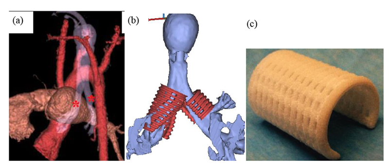
Splint engineering process from patient image to laser sintered splint. (a) Generation of patient airway model from CT scan to determine malacic segment length and diameter. Asterisks mark bilateral malacic segments (b) STL models for bilateral splints generated from image-based design that serves as basis for finite element mesh and laser sintering. (e) final laser sintered PCL splint.
Finishing biocompatability studies, geometric tolerancing, and mechanical testing allows design verification to be completed by comparing test results to design inputs. If the test result meets the design input requirement (which could be as simple as a “pass” on a test to a more nuanced result of meeting a target value within an accepted range), the design is verified and design validation is performed. It is of course critical that the design be verified if the design hypothesis is to be rigorously tested as if a design not meeting design requirements were to fail in design validation, one could not be certain whether the original design hypothesis must be rejected or the device itself was faulty.
We have previously demonstrated that splints meet mechanical design inputs of allowing less than 40% displacement under 40 N compression loads parallel to the splint opening while allowing at least 1.2 times the original splint opening12. Design validation requires that we test the three major components of our design hypothesis: 1) the splint must create immediate patency in airway collapsing due to TBM, 2) the splint must maintain this patency while allowing airway growth over the long term, and 3) the splint must not cause adverse tissue reactions. Since the splint is a class III device, design validation must be performed in clinical trials as well as in pre-clinical animal models. We have previously demonstrated that the splint creates immediate patency in both a large pre-clinical porcine model21, as well as in human patients6,7under emergency use, but a controlled clinical trial is necessary for final approval.
In this study, we present results testing the effect of splint design, specifically splint wall thickness and resulting opening stiffness, on airway growth in a large porcine pre-clinical model. In this model, splints 14mm inner in diameter, 25mm long with a 90° opening were sutured over intact trachea of 1 month old Yorkshire domestic pigs. Three different splint wall thicknesses of 3mm, 4mm and 5mm were designed using the image-based MATLAB design program and fabricated using 3D laser sintering from PCL, with n=5 pigs per splint diameter. An opening stiffness was measured by placing hooks along the splint opening and applying a tension load to open the splint (Fig. 2). Pigs were followed for 8 months at which time a CT scan was taken to determine tracheal growth.
Figure 2.
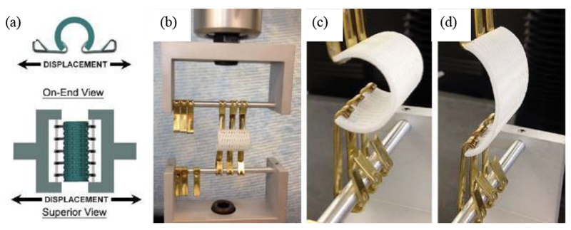
Example of hook opening test of 3D printed splint to determine opening displacement and geometric opening stiffness under 15 N load. (a) schematic of testing setup. (b) splint placed in testing machine. (c) start of opening load. (d) opening load at 15N.
3D Printed Mandibular Pre-fabricated Flap
Our second example extends the concept of patient specific design and 3D biomaterial fabrication to create a vascularized bone construct for mandibular reconstruction using a prefabricated flap approach. The goal of this application is to create a structural/biologic construct to reconstruct a large mandibular defect. Our design hypothesis was that a scaffold structure optimized to balance load bearing and mass transport integrated with BMP2 could be successfully implanted as a pre-fabricated flap in the latissimus dorsi muscle, support bone and vascular growth, then be transplanted as entire unit with microvascular hook-up to regenerate for mandibular reconstruction. The transplanted structural/biologic construct is a composite consisting of a 3D printed PCL scaffold with fixation rims, bone tissue regenerated through bone morphogenetic protein 2 (BMP2) delivery, complete vascularization and associated muscle. The construct was tested in a porcine preclinical model using a prefabricated flap approach.
Design inputs for the prefabricated mandibular flap (denoted with the prefix PF for pre-fabricated flap) were as follows:
-
PF1.
Replicate complex mandibular angle anatomy for a large volume bone/soft tissue defect
-
PF2.
Withstand porcine mastication loads up to 600 N
-
PF3.
Regenerate significant volumes of bone tissue (> 20% bone of scaffold pore volume) prior to flap transfer
-
PF4.
Support vascularization with attached soft tissue prior to flap transfer
-
PF5.
Provide attached pedicles for vascular anastomosis
-
PF6.
Provide secure methods for fixing structural/biologic construct to remaining mandible
In this study, we report design validation of PF1, PF3, and PF6 specifically, looking at the capability to replicate complex mandibular anatomy with a 3D printed scaffold, to utilize this scaffold to regenerate bone prior to flap transfer, and to design fabricate regions for fixation of the mandibular scaffold to the border of the mandibular defect.
To achieve these goals, we performed topology optimization design22,23 directly from a CT scan of a Yorkshire pig of similar size and age to the animal which underwent the procedure. Mimics (Materialise™) software was used to segment the pig mandible and subsequently extract the mandibular angle as a scaffold domain for reconstruction. Dilation was used to append a transition region from the angle scaffold region to the remaining mandible through which screw fixation secures the scaffold to the remaining mandible. A 10-node tetrahedral mesh of the scaffold/fixation region, cylinders representing screw fixation, and the remaining mandible was generated from the segmented image using Mimics and 3-matics (Materialise™) software. The mesh was transferred to Hypermesh and Optistruct (Altair Engineering™) . The front dentition of the mandible was fixed to zero displacement and a mastication force of 600 N was applied to the mandibular angle. A macroscopic topology optimization analysis was run in which the objective function was to minimize the total construct strain energy density under a volume fraction constraint of 40%. This effectively produces the stiffness structure possible for a fixed amount of material by distributing that material efficiently in the most highly loaded regions. The macroscopic material layout, however, is a volume averaged measure and does not define a pore space. To achieve a balance between maximum stiffness (effective bulk modulus) and mass transport (effective diffusivity) possible for the macroscopic prediction of optimal volume fraction, we further utilized our own custom written microscopic topology optimization program24. This program generates an optimal pore shape within a mathematical unit cell that is repeated in 3D space to generate a porous architecture. This porous architecture is combined with the macroscopic shape using Boolean intersection to produce the final scaffold design.
The two scale topology optimization approach generates complex porous designs which are not feasible to fabricate by traditional manufacturing methods. Again, we utilized the PCL laser sintering approach to fabricate the mandibular scaffold as described in the section on splint manufacturing. Once fabricated, the scaffold was sterilized using Ethylene Oxide. The first stage of flap prefabrication was to pipette a solution containing 1mg of rhBMP2 onto the scaffold surface for 45 minutes at room temperature25. The scaffold was then implanted into the latissimus dorsi muscle of a 6 month old Yorkshire Pig. Following 2 months in the muscle, a CT scan was taken to assess bone growth within the scaffold during muscle implantation. Subsequently, the scaffold, regenerated bone, adjacent vascular pedicle, and surrounding muscle were then transplanted, fixed to a surgically created mandibular angle defect and anastamosed to the carotid artery and internal jugular vein in the neck to provide immediate perfusion to the vascular network which had grown into the scaffold during the muscle implantation.
Results
3D Printed Tracheal Splint Effects on Growth
The design input for splint opening displacement was 20% of the splint opening width under a 15N load. The splints have an opening angle of 90°, with an inner diameter of 14mm. Account for the wall thickness of each splint, the opening displacement should range from 2.67mm for the 3mm wall thickness splint to 3mm for the 5mm wall thickness splint. Opening tests on laser sintered 3mm and 4mm wall thickness splints showed opening displacements of 9.95 ± 0.69 mm (n=6 specimens) and 3.87 ± 0.15 mm (n=6 specimens), respectively for the 3mm and 4mm wall thickness splints. 5mm wall thickness splints could not be tested in opening, but extrapolating tests on 2mm, 3mm and 4mm splints would suggest that 5mm wall thickness splints would not meet the design input requirement of at least 3mm opening displacement under 15N load. The geometric opening stiffness (calculated as the linear slope of the load displacement curve) was 1.97 ± 0.12 N/mm for the 3mm wall thickness splint and 4.31 ± 0.15 N/mm for 4mm wall thickness splint. Again, extrapolating data from tests on 2mm, 3mm and 4mm wall thickness splints would suggest the 5mm wall thickness splint would have an opening geometric stiffness greater than 8 N/mm.
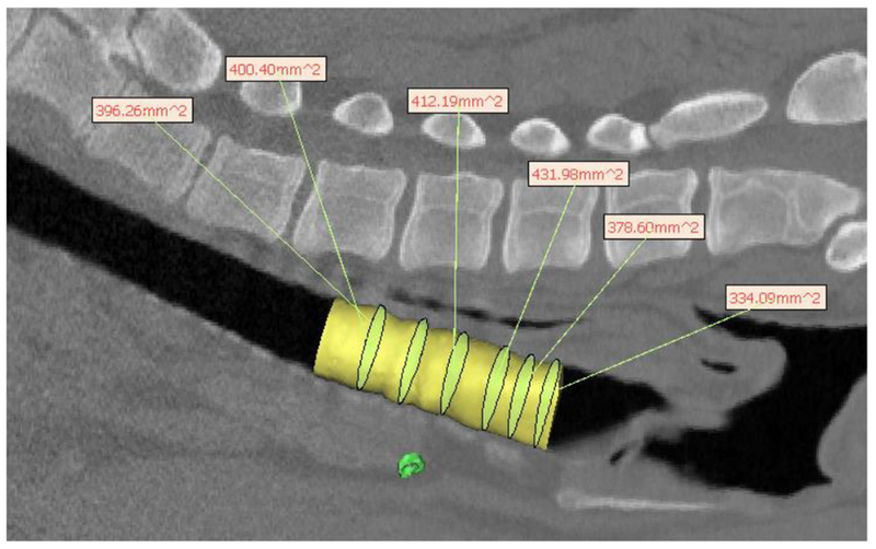
A total of 15 pigs were implanted with 3D printed splint, 5 pigs for each wall thickness design (Fig. 3). Of these 15 pigs, 7 pigs (3 each with 4 and 5mm wall thickness splints and 1 with a 3mm wall thickness splint) had to be euthanized within 1 month of surgery, predominately due to tracheal stenosis. The remaining pigs were CT scanned and then euthanized after the study period of 7-8 months. Hydraulic diameter and cross-sectional area measurements were made in MIMICS software (Materialise™) along the tracheal length for the 3mm (Fig. 4), 4mm (Fig. 5) and 5mm (Fig 6) wall thickness splints. The final hydraulic diameters (HD) were 20.7 ± 1.8 mm (n=4) for the 3mm wall thickness splints, 19.2 ± 3.8 mm (n=2) for the 4mm wall thickness splints, and 14.6 ± 0.7 mm (n=2) for the 5mm wall thickness splints. The final cross sectional areas (CSA) were 345.7 ± 60.9 mm2 (n=4) for the 3mm wall thickness splints, 316.0 ± 107.6 mm2 (n=2) for the 4mm wall thickness splints, and 219.6 ± 23.9 mm2 (n=2) for the 5mm wall thickness splints.
Figure 3.

STL design for (a) 3mm wall thickness splint (b) 4mm wall thickness splint and (c) 5mm wall thickness splint.
Figure 4.
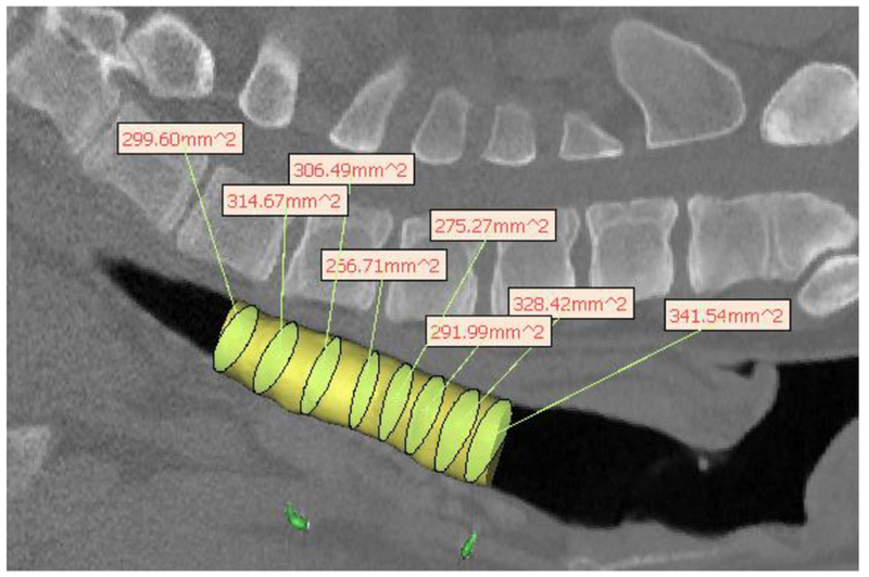
Hydraulic diameter measurement from pig CT scan for 3mm wall thickness splint deisgn showing uniformity of growth after 8 months in a pig model. The yellow cylinder represents the tracheal lumen. The yellow-green ellipsoids within the cylinder are the best fit ellipsoids from which the hydraulic diameter is calculated, which are then shown in the text boxes.
Figure 5.
Hydraulic diameter measurement from pig CT scan for 4mm wall thickness splint design showing uniformity of growth after 8 months in a pig model. The yellow cylinder represents the tracheal lumen. The yellow-green ellipsoids within the cylinder are the best fit ellipsoids from which the hydraulic diameter is calculated, which are then shown in the text boxes.
Figure 6.
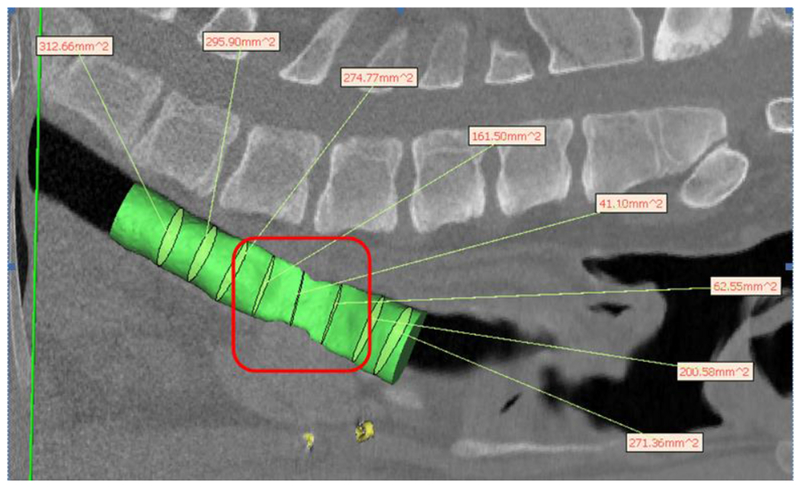
Hydraulic diameter measurement from CT scan of on 5mm wall thickness splint showing severe stenosis and lack of growth under splint after 8 months in a pig model. The green cylinder represents the tracheal lumen. The green ellipsoids within the cylinder are the best fit ellipsoids from which the hydraulic diameter is calculated, which are shown in the text boxes. Stenotic region underneath splint is outlined in red indicating “crumpled” region of stenosis.
Although pigs were not scanned at surgery to determine initial tracheal dimensions, a conservative estimate can be obtained from the initial splint HD and CSA, which were 14 mm and 154 mm2, respectively. Thus, it is clear that both the 3mm and 4mm wall thickness splints allowed significant tracheal growth over 8 months, a 48% and 37% increase in HD respectively. Moreover, as seen from Figs. 3–5, while there is little variation in trachea geometry with the 3mm and 4mm splint, there is extreme stenosis in the area underneath the 5mm splint. A graph (Fig. 7) of tracheal CSA by pig show significant growth for the 3mm and 4mm wall thickness splinted tracheas past the initial splint CSA with little standard deviation while the graphs of the 5mm wall thickness splints show little growth past the initial splint CSA with large standard deviations, reflecting the region of stenosis.
Figure 7.
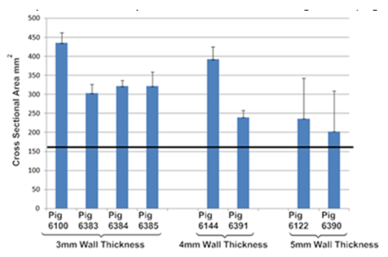
Mean and standard deviation of cross-sectional area along tracheal lumen for all long term surviving pigs. Results are grouped by splint design wall thickness (i.e. 3mm, 4mm, 5mm). Straight black line represents initial cross-sectional area of implanted splint.
3D Printed Pre-Fabricated Mandibular Flap
The complete engineering process for the prefabricated flap from initial CT scan, topology optimization, final design, 3D printed scaffold, BMP2 loading, muscle implantation and craniofacial transplantation is shown in Fig. 8. A CT scan taken after two months (Fig. 9a) showed bone growth distributed throughout the scaffold. The volume of total bone ingrowth was 4.5 cm3, which occupied 24.3% of available pore space, meeting the design requirement for bone growth. At two months the vascularized scaffold, regenerate bone, associated vascular pedicles and muscle (Fig. 9b) were transplanted to reconstruct a surgically created mandibular angle defect in the same animal. Patency of the flap was confirmed immediately post-surgery. However, two weeks post-surgery it was determined that patency was not sufficient to keep the flap viable and the animal was euthanized.
Figure 8.
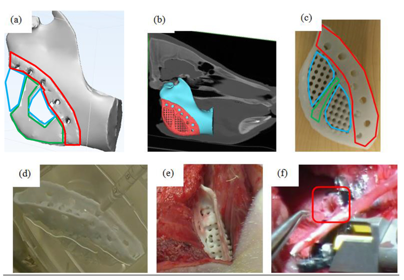
Engineering and development process for prefabricated flap. (a) Initial material layout predicted by global topology optimization under mastication load. Areas outlined in green were predicted to be fully dense while those outline in blue were predicted to be porous. Area outlined in red was designed for fixation to the remaining mandible. (b) final scaffold design after substitution of local topology optimized pore structure attached to mandibular angle defect on CT based model. (c) 3D printed PCL scaffold showing fixation rim, pore structure for biologic loading and solid material for load bearing. Areas outlined in red are portions of the scaffold designed for fixation, areas outline in green are those areas predicted to need full solid material from topology optimization, while blue areas are porous areas predicted by the topology optimization into which a designed porous architecture is substituted. Note that a rim was added posterior and inferior to provide a smooth interface to soft tissue in the final design. (d) intra-operative loading of BMP2 onto scaffold. (e) muscle implantation of BMP2 loaded scaffold. (f) transplantation of vascularized, soft tissue bone scaffold under mandibular angle, specifically showing process of anastomosis of pedicle (outlined) to carotid artery.
Figure 9.
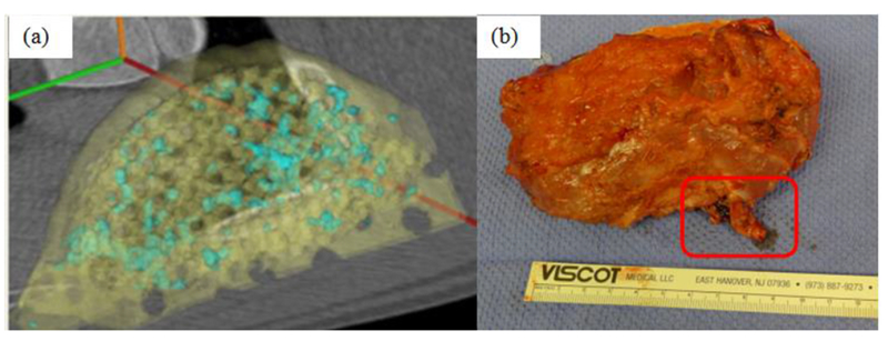
Performance of 3D printed prefabricated flap during muscle implantation. (a) CT scan of bone growth (blue) on scaffold (yellow) after 2 months of implantation in the latissimus dorsi muscle. A total of 4.5 cm3 of bone grew localized on the scaffold after 2 months in the muscle. (b) composite vascularized bone/soft tissue construct on surgical table prior to transplant. Vascular pedicle for microvascular hookup is outlined. Construct is 11cm × ~6cm by 2cm.
Discussion
The purpose of this paper was twofold: 1) present results for specific pre-clinical large animal experiments utilizing patient specific 3D printed implants and 2) present a general translational paradigm of integrating design control with image-based patient specific design and 3D biomaterial printing. The second purpose will become increasingly necessary as more academic institutions actively translate medical devices and implants into clinical use without first licensing it to industrial partners. Such a model, or related academic-industrial partner models, will be necessary to address orphan device markets, especially those of pediatrics. Indeed, the evolution of 3D biomaterial printing with image-based patient design software has made such academic translational models possible, as prior to 3D biomaterial printing the manufacturing start-up costs alone would have made such translational endeavors unthinkable.
However, to embark on translational endeavors, a device must be designed and developed under FDA design control guidelines11,12 as part of Quality Systems. In general, the flow of design control is the same regardless of what methods are used to design and manufacture the device. No matter how a device is designed and manufactured, it must still meet design inputs (design verification) and the ability of the device to satisfy the initial clinical design hypothesis and mitigate the clinical indication must be tested through pre-clinical and if necessary clinical studies (design validation). Nonetheless, image-based patient specific design and 3D printing uniquely impact the design control process. First, image-based design coupled with 3D printing enable a much broader and richer array of potential medical devices than could be previously achieved with traditional design and manufacturing processes. Most notably the ability to make patient specific and custom devices in an economically feasible manner that will disrupt our traditional idea of what constitutes a medical device. Second, this ability to make unique patient specific devices in small lots will challenge our ability to ensure quality control because the same devices will not be repeatedly made in lots of thousands or tens of thousands. Third, a corollary of small lot manufacturing is that large variations in designs, materials, and 3D printing processes themselves will exhibit significant variation in build quality, again challenging the notion that we can validate a single process and requiring the development of new quality control methods as part of a new regulatory science approach. Indeed, the FDA has recently issued a draft guidance document on the quality issues associated with 3D printed medical devices26,27.
The aspects of 3D printing noted in the previous paragraph apply broadly to quality and design control, thus impacting clinical translation of all 3D printed devices whether they are metallic implants or live cells. However, the specific results presented in both example studies also raise important issues for clinical translation which may only be addressed through integration of image-based patient specific design and 3D biomaterial printing. The first issue raised in the case of the 3D printed splint is effect of pediatric implants on tissue growth. Part of our clinical hypothesis was that the airway would grow if the splint opening compliance met the design input of 20% opening displacement when subject to 15 N growth loading. The results in the large pig model clearly demonstrate that significant growth did occur if the splint allows 20% displacement under 15 N load, equivalent to 4 N/mm or less opening geometric stiffness. Clinical observations in infants also demonstrated growth in splints also meeting this design input, supporting evidence that meeting this design input allows airway growth7. Conversely, splints with higher opening stiffness allowing less than 20% opening displacement (> 8 N/mm opening geometric stiffness) severely restricted airway growth.
The question of growth is critical for pediatric implant/scaffold development. Pediatrics remains an underserved medical device market. It is estimated that pediatric device development lags a decade behind that of adult device development, with many pediatric devices being jury rigged to fit as a first priority and growth remaining a distant secondary concern2. Again, integrating image-based patient specific design with 3D printing allows the pediatric market to be addressed, since the cost per part using 3D printing remains the same for 1 part as for 10,000 parts1. However, with growth, we must introduce the concept of 4D printing, that is, 3D printed devices that change shape as a function of the 4th dimension, time. 4D printing was first introduced in the context of architecture28, but has recently been redefined as 3D printed structures that undergo self-assembly, self-folding, or self-accommodating shape changes over time in response to external stimuli29,30. Although initially defined for shape changes taking minutes or hours, the type of design, material and fabrication based 4D printing designed to accommodate pediatric tissue growth requires planning and designing for changes occurring over months and years. Examples of using 4D printing to allow long term in vivo growth include the design and printing of structural mechanisms that allow large displacements in one direction but preclude displacement in the opposite direction due to contact.
Long term 4D printing also encompasses the general time dependent degradation of bioresorbable material. In this case, the long term molecular weight loss and subsequent loss of mechanical stiffness and strength would make it easier for tissues to grow and change shape. The great challenge of course is to better understand the kinetics of material degradation and tissue growth. This requires a more rigorous study of material degradation and fatigue for 3D printed resorbable materials to develop more rigorous design inputs. More rigorous application of design control and development of design inputs for time dependent 4D printed devices will also require more detailed characterization of the time dependent development of tissue mechanical properties. It will also require the ability to model tissue growth31,32 and use such growth models in 4D printed pediatric device design and development.
The second example, a 3D printed pre-fabricated flap addresses a critical issue in regenerative medicine, namely vascularization and bone growth for reconstruction of large craniofacial defects. A number of innovative new approaches have utilized 3D printing to actually fabricate vascular networks33. However, such approaches are likely down the road for clinical applications. The idea of pre-fabricated flaps for complex craniofacial has previously been pursued in large animal models and even human patients with mixed success34–40. These approaches, however, did not utilize image-based patient specific design to create a base scaffold to deliver biologics. Our example integrated not only image-based patient specific topology design with 3D biomaterial printing for the scaffold, but also integrated fixation with intra-OR BMP2 loading25. Our approach did yield significant bone development with associated vascularization through the construct during muscle implantation, followed by successful transplantation of the construct for mandibular reconstruction in a 9 hour operation with microsurgical anastomosis. However, the flap failed after two weeks due to occlusion of the vascular pedicle.
This failure underscores challenges remaining to be solved in prefabricated flaps. First and foremost, as in any tissue engineering application, the optimal biologic mixture, dosage and delivery kinetics from the 3D printed scaffold must be determined for the prefabricated flap. This can best be solved by rigorous and intensive study of tissue regeneration on 3D printed scaffolds loaded with biologics in the muscle site. Specifically, it will be important to monitor vascularization and appropriate tissue development in the muscular site as a function of time and delivered biologic. The ability to more rigorously specify design inputs for pre-fabricated flaps in terms of biologic delivery, degree and mechanical properties of regenerate bone tissue prior to transplantation, as well as characterizing the degree of vascularization within design inputs will be critical to improving pre-fabricated flaps for tissue reconstruction.
Criteria regarding the amount of bone, soft tissue, and vascular regeneration sufficient to support long term flap viability and reconstructive success will need to be developed from such studies. In a design control framework, it is critical to develop and refine such criteria through pre-clinical studies and human clinical trials. It should be noted that our specification of 20% scaffold pore volume fill (PF3) is an initial estimate. Previous studies utilizing pre-fabricated flaps for mandibular reconstruction in humans transplanted the flap after 7 weeks34 and 12 weeks38 respectively, similar to our time period of 8 weeks. However, actual regenerate bone volume was not reported at the time of transplant. Also, these studies used titanium trays for load bearing, but such trays have the disadvantage of causing dehiscence.
Furthermore, although previous animal studies have examined pre-fabricated flaps, using morcellized bone graft in a cylindrical tube placed in sheep rib periostium. These studies total tissue volume of 6cm3. However, this tissue volume included the initial mineralized bone graft and actually dropped from 6cm3 at 3 week to 3cm3 at 6 weeks. These results suggest that there may be a peak formation time for bone after which bone resorption occurs, although it is unclear in these results if the initial bone graft was being resorbed or the newly regenerate bone. It is clear that development and translation of pre-fabricated flaps using 3D printed scaffolds (or any scaffolding) coupled with biologic delivery presents many unknowns that must be answered through detailed pre-clinical investigations. We recognize that our design inputs for the current study, although in line with previous pre-clinical animal and human clinical studies, are estimates at best that must be refined through iterative pre-clinical studies to develop a rigorous design control approach.
It will be important to develop optimal surgical animal models that best test the transplantation of an optimized vascularized tissue developed using “in vivo bioreactor” techniques35. It is clear that 3D printing will play a critical role in prefabricated flaps due to its ability to create geometrically complex scaffolds that can match any anatomic defect and its ability to generate pore architectures in patterns that achieve an optimal balance between load bearing, mass transport, biologic delivery and tissue ingrowth.
In conclusion, this paper has illustrated integration of image-based patient specific design and 3D biomaterial printing to create resorbable patient specific devices under design control, and furthermore to test these devices in large pre-clinical animal models. It was demonstrated that 3D printed splints fabricated according to design requirements did allow growth in a large animal model, and that 3D printed scaffolds for prefabricated flaps supported vascularization and bone growth in a muscle site prior to transplantation. These are merely the first steps, however, to integrate and study how image-based designed and 3D biomaterial printing can be used within a design control context to address challenges such as growth in pediatric devices and vascularization of prefabricated flaps for large volume tissue reconstruction.
ACKNOWLEDGMENT
The tracheal splint large animal study was supported by NIH/NICHD R21 HD 076370 (SJH/GEG co-PI; MBW co-I). The prefabricated flap large animal study was supported by NIH/NIDCR R21 DE 022439 (SJH/SPE co-PI; MBW co-I). Dr. Morrison was supported by NIH T32 DC 005356. We gratefully acknowledge the contributions of Drs. Derek Milner, Aaron Maki and Chanaka Rabel for the large animal surgeries.
Funding Sources
NIH/NICHD R21 HD 076370 (SJH/GEG), NIH/NIDCR R21 DE 022439 (SJH/SPE), T32 DC 005356 (RJM).
REFERENCES
- 1.Connor BP; Manogharan GP; Martof AN; Rodomsky LM; Rodomsky CM; Jordan DC; Limperos JW Making sense of 3-D printing: creating a map of additive manufacturing products and services. Additive Manufacutring. 2014, 1, 64–76. [Google Scholar]
- 2.Tarkan L; Medical Devices Fall Short for Children, New York Times, May 6, 2013. [Google Scholar]
- 3.Schantz JT;, Lim TC;, Ning C; Teoh SH; Tan KC; Wang SC; Hutmacher DW Cranioplasty after trephination using a novel biodegradable burr hole cover: technical case report. Neurosurgery 2006. 58S: ONS–E176. [DOI] [PubMed] [Google Scholar]
- 4.Salmi M; Tuomi J; Kaija‐Stiina Paloheimo; Roy Björkstrand; Paloheimo M; Salo J; Kontio R; Karri Mesimäki; Antti A. Mäkitie. Patient‐specific reconstruction with 3D modeling and DMLS additive manufacturing. Rapid Prototyping Journal 2012, 18, 209–214. [Google Scholar]
- 5.Liu Y; Lim J; Teoh S Review: development of clinically relevant scaffolds for vascularised bone tissue engineering. Biotechnol. Adv 2013, 31, 688–705. [DOI] [PubMed] [Google Scholar]
- 6.Zopf DA; Hollister SJ; Nelson ME; Ohye RG; Green GE Bioresorbable airway splint created with a three-dimensional printer. N. Engl. J. Med 2013, 368, 2043–2045. [DOI] [PubMed] [Google Scholar]
- 7.Morrison RJ; Hollister SJ; Niedner MF; Mahani MG; Park AH; Mehta DK; Ohye RG; Green GE Mitigation of tracheobronchomalacia with 3D-printed personalized medical devices in pediatric patients. Sci. Transl. Med 2015, 7, 285ra64. [DOI] [PMC free article] [PubMed] [Google Scholar]
- 8.Rasperini G; Pilipchuk SP; Flanagan CL; Park CH; Pagni G; Hollister SJ; Giannobile WV 3D-printed Bioresorbable Scaffold for Periodontal Repair. J. Dent. Res 2015, 94, 153S–7S. [DOI] [PubMed] [Google Scholar]
- 9.Volk HD; Stevens MM; Mooney DJ; Grainger DW; Duda GN Key elements for nourishing the translational research environment. Sci. Transl. Med 2015, 7, 282cm2. [DOI] [PMC free article] [PubMed] [Google Scholar]
- 10.Duda GN; Grainger DW; Frisk ML; Bruckner-Tuderman L; Carr A; Dirnagl U; Einhaupl KM; Gottschalk S; Gruskin E; Huber C; June CH; Mooney DJ; Rietschel ET; Schutte G; Seeger W; Stevens MM; Urban R; Veldman A; Wess G; Volk HD Changing the mindset in life sciences toward translation: a consensus. Sci. Transl. Med 2014, 6, 264cm12. [DOI] [PubMed] [Google Scholar]
- 11. http://www.fda.gov/MedicalDevices/DeviceRegulationandGuidance/GuidanceDocuments/ucm070627.htm.
- 12.Hollister SJ; Flanagan CL; Zopf DA; Morrison RJ; Nasser H; Patel JJ; Ebramzadeh E; Sangiorgio SN; Wheeler MB; Green GE Design control for clinical translation of 3D printed modular scaffolds. Ann. Biomed. Eng 2015, 43, 774–786. [DOI] [PMC free article] [PubMed] [Google Scholar]
- 13.Morrison RJ; Kashlan KN; Flanangan CL; Wright JK; Green GE; Hollister SJ; Weatherwax KJ Regulatory Considerations in the Design and Manufacturing of Implantable 3D-Printed Medical Devices. Clin. Transl. Sci 2015, 8, 594–600. [DOI] [PMC free article] [PubMed] [Google Scholar]
- 14.Shaffer TH, Bhutani VK Alterations in bulk modulus of trachea during development. Respiration 1980, 39:344–350. [DOI] [PubMed] [Google Scholar]
- 15.Bhutani VK, Shaffer TH Time-dependent tracheal deformation in fetal, neonatal and adultu rabbits. Pediatr. Res 1982. 16:830–833. [DOI] [PubMed] [Google Scholar]
- 16.Deoras KS, Wolfson MR, Searls RL, Hilfer R, Shaffer TH Developmental changes in tracheal structure. Pediatr Res 1991. 30:170–175. [DOI] [PubMed] [Google Scholar]
- 17.Williams JM, Adewunmi A, Schek RM, Flanagan CL, Krebsbach PH, Feinberg SE, et al. Bone tissue engineering using polycaprolactone scaffolds fabricated via selective laser sintering. Biomaterials. 2005;26:4817–27. [DOI] [PubMed] [Google Scholar]
- 18.Partee B, Hollister SJ, Das S: Selective laser sintering process optimization for layered manufacturing of CAPA 6501 polycaprolactone bone tissue engineering scaffolds. ASME J. Man. Sci Eng, 2006; 128:531–540. [Google Scholar]
- 19.Eshraghi S, Das S. Mechanical and microstructural properties of polycaprolactone scaffolds with one-dimensional, two-dimensional, and three-dimensional orthogonally oriented porous architectures produced by selective laser sintering. Acta Biomater. 2010; 6:2467–76. [DOI] [PMC free article] [PubMed] [Google Scholar]
- 20.Eshraghi S, Das S, 2012. Micromechanical finite-element modeling and experimental characterization of the compressive mechanical properties of polycaprolactone-hydroxyapatite composite scaffolds prepared by selective laser sintering for bone tissue engineering. Acta Biomaterialia 2012; 8:3138–3143. [DOI] [PMC free article] [PubMed] [Google Scholar]
- 21.Zopf DA, Flanagan CL, Wheeler M, Hollister SJ, Green GE., Treatment of severe porcine tracheomalacia with a 3-dimensionally printed, bioresorbable, external airway splint. JAMA Otolaryngology Head Neck Surg 2014; 140:66–71. [DOI] [PMC free article] [PubMed] [Google Scholar]
- 22.Bendsoe MP, Kikuchi N. Generating optimal topologies in structural design using a homogenization method. Comp Meth App Mech Eng 1988; 71:197–224. [Google Scholar]
- 23.Hassani B, Hinton E. Homogenization and Structural Topology Optimization, 1999, Springer London. [Google Scholar]
- 24.Kang H, Lin CY, Hollister SJ. Topology optimization of thee dimensional tissue engineering scaffold architectures for prescribed bulk modulus and diffusivity. Struct Multidisc Optimization 2010; 42:633–644. [DOI] [PMC free article] [PubMed] [Google Scholar]
- 25.Patel JJ, Flanagan CL, Hollister SJ. Bone morphogenetic protein-2 adsorption onto poly-e-caprolactone better preserves bioactivity in vitro and produces more bone in vivo than conjugation under clinically relevant loading scenarios. Tissue Eng C, 2015, 21:489–498. [DOI] [PMC free article] [PubMed] [Google Scholar]
- 26.Di Prima M, Coburn J, Hwang D, Kelly J, Khairuzzaman A, Ricles L. Additively manufactured medical products – the FDA perspective. 3D Printing in Medicine. 2016;2(1):1–6. [DOI] [PMC free article] [PubMed] [Google Scholar]
- 27. http://www.fda.gov/downloads/MedicalDevices/DeviceRegulationandGuidance/GuidanceDocuments/UCM499809.pdf.
- 28.Tibbits S, 4D printing: Multi-material shape change. Architectural Design, 2014, 84:116–121. [Google Scholar]
- 29.An J, Chua CK, Mironov V. A perspective on 4D Bioprinting, Int. J. Bioprinting, 2016, 2:3–5. [Google Scholar]
- 30.Gao B, Yang Q, Zhao X, Jin G, Ma Y, Xu F. 4D Bioprinting for Biomedical Applications, Trends in Biotechnology, (in press). [DOI] [PubMed] [Google Scholar]
- 31.Ambrosi D, Ateshian GA, Arruda EM, Cowin SC, Dumais J, Goriely A, Holzapfel GA, Humphrey JD, Kemkemer R, Kuhl E, Olberding JE, Taber LA, Garikipati K. Perpsectives on biological growth and remodeling, J. Mech. Phy. Solids, 2011, 59:863–883. [DOI] [PMC free article] [PubMed] [Google Scholar]
- 32.Menzel A, Kuhl E. Frontiers in growth and remodeling, Mech. Res. Comm, 2012, 42:1–14. [DOI] [PMC free article] [PubMed] [Google Scholar]
- 33.Richards D, Jia J, Yost M, Markwald R, & Mei Y 3D Bioprinting for Vascularized Tissue Fabrication. Annals of biomedical engineering, 2016, 1–16. [DOI] [PMC free article] [PubMed] [Google Scholar]
- 34.Warnke PH, Spring ING, Wiltfang J, Acil Y, Eufinger H, Wehmoller M, Russo PAJ, Sherry E, Behrens E, Terheyden H. Growth and transplantation of a custom vascularized bone graft in a man., Lancet, 2004, 364:766–770. [DOI] [PubMed] [Google Scholar]
- 35.Warnke PH, Wiltfang J, Springer I, Acil Y, Bolte H, Kosmahl M, Russo PAH, Sherry E, Lutzen U, Wolfart S, Terheyden H. Man as living bioreactor: fate of an exogenously prepared customized tissue-engineered mandible. Biomaterials, 2006, 27:3163–3167. [DOI] [PubMed] [Google Scholar]
- 36.Di Bella C, Lucarelli E, Donati D Historical review of bone prefabrication. La Chirurgia degli organi di movimento, 2008, 92:73–78. [DOI] [PubMed] [Google Scholar]
- 37.Torroni A Engineered bone grafts and bone flaps for maxillofacial defects: state of the art. J. Oral Maxillofac Surg, 2009, 67:1121–1127. [DOI] [PubMed] [Google Scholar]
- 38.Wiltfang J, Rohnen M, Egberts JH, Lutzen U, Wieker H, Acil Y, Naujokat H. Man as a living bioreactor: prefabrication of a custom vascularized bone graft in the gastrocolic omentum. Tissue Eng C, 2016, 22: 740–746. [DOI] [PubMed] [Google Scholar]
- 39.Cheng MH, Brey EM, Allori AC, Gassman A, Chang DW, Patrick CW Jr., Miller MJ Periosteum-guided prefabrication of vascularized bone of clinical shape and volume. Plast Reconstr. Surgy 124:787–795. [DOI] [PubMed] [Google Scholar]
- 40.Cheng MH, Brey EM, Allori A, Satterfiled WC, Change DW, Patrick CW Jr., Miller MJ Ovine model for engineering bone segments. Tissue Eng, 2005, 11:214–225. [DOI] [PubMed] [Google Scholar]


