

CONSPECTUS:
Electrospinning is a simple and versatile technique that relies on the electrostatic repulsion between surface charges to continuously draw nanofibers from a viscoelastic fluid. It has been applied to successfully produce nanofibers, with diameters down to tens of nanometers, from a rich variety of materials, including polymers, ceramics, small molecules, and their combinations. In addition to solid nanofibers with a smooth surface, electrospinning has also been adapted to generate nanofibers with a number of secondary structures, including those characterized by a porous, hollow, or core–sheath structure. The surface and/or interior of such nanofibers can be further functionalized with molecular species or nanoparticles during or after an electrospinning process. In addition, electrospun nanofibers can be assembled into ordered arrays or hierarchical structures by manipulation of their alignment, stacking, and/or folding. All of these attributes make electrospun nanofibers well-suited for a broad spectrum of applications, including those related to air filtration, water purification, heterogeneous catalysis, environmental protection, smart textiles, surface coating, energy harvesting/conversion/storage, encapsulation of bioactive species, drug delivery, tissue engineering, and regenerative medicine.
Over the past 15 years, our group has extensively explored the use of electrospun nanofibers for a range of applications. Here we mainly focus on two examples: (i) use of ceramic nanofibers as catalytic supports for noble-metal nanoparticles and (ii) exploration of polymeric nanofibers as scaffolding materials for tissue regeneration. Because of their high porosity, high surface area to volume ratio, well-controlled composition, and good thermal stability, nonwoven membranes made of ceramic nanofibers are terrific supports for catalysts based on noble-metal nanoparticles. We have investigated the use of ceramic nanofibers made of various oxides, including SiO2, TiO2, SnO2, CeO2, and ZrO2, as supports for heterogeneous catalysts based on noble metals such as Au, Pt, Pd, and Rh. On the other hand, the diameter, composition, alignment, porosity, and surface properties of polymeric nanofibers can be engineered in a controllable fashion to mimic the hierarchical architecture of an extracellular matrix and help manipulate cell behaviors for tissue engineering and regenerative medicine. To this end, we can mimic the native structure and morphology of the extracellular matrix in tendon using uniaxially aligned nanofibers; we can use radially aligned nanofibers to direct the migration of cells from the periphery to the center in an effort to speed up wound healing; and we can also use uniaxially aligned nanofibers to guide and expedite the extension of neurites for peripheral nerve repair. Furthermore, we can replicate the anatomic structures at the tendon-to-bone insertion using nanofiber scaffolds with graded mineral coatings. In this Account, we aim to demonstrate the unique capabilities of electrospun nanofibers as porous supports for heterogeneous catalysis and as functional scaffolds for tissue regeneration by concentrating on some of the recent results.
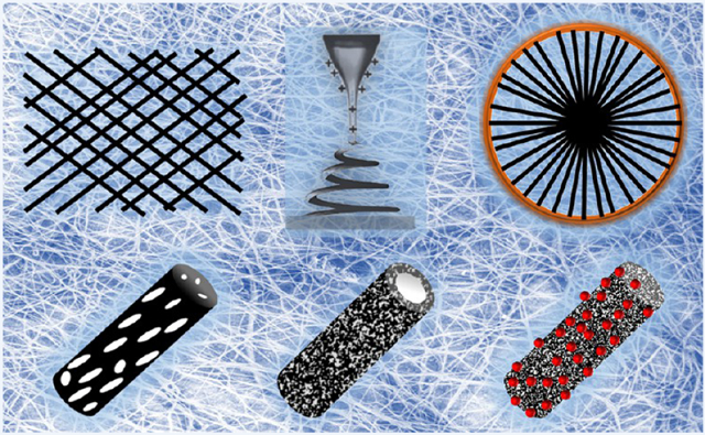
Graphical Abstract
1. INTRODUCTION
It was discovered over a century ago that ultrathin fibers could be drawn from a viscoelastic fluid under the influence of a strong electric field. Known as electrospinning, this technique has been rediscovered and refined by many researchers,1–8 and now it can be used to produce continuous fibers with diameters down to tens of nanometers.
The Web of Science first took the term of “electrospinning” into record in 1993 by referring to a conference paper written by Darrell H. Reneker.9 This paper highlighted the unique features of electrospinning as a fabrication technique and the distinct morphology of electrospun nanofibers. Since then, there has been a surge of interest in electrospinning, primarily due to its capability to produce fibers with ultrathin diameters for a wide variety of applications. In this Account, we focus on the contributions from our own group to this remarkable technique. We begin by describing the principle of electro-spinning and then briefly discuss the methods developed for controlling the composition, structure, porosity, and surface properties of electrospun nanofibers. In the last section, we highlight some applications of the electrospun nanofibers in heterogeneous catalysis and biomedical research.
2. SETUP AND PRINCIPLE OF ELECTROSPINNING
The setup for electrospinning is simple and easily accessible. It typically consists of four major components: a high-voltage power supply, a syringe pump, a spinneret, and a collector (Figure 1A).10,11 When a small amount of a viscoelastic fluid is pumped out through the spinneret, it tends to form a spherical droplet as a result of the confinement of surface tension. Because the droplet is connected to a high-voltage power supply, its surface will be quickly covered by charges of the same sign. The repulsion among these charges will counteract the surface tension and destabilize the spherical shape. If the repulsion is strong enough to overcome the surface tension, the droplet will be deformed into a conical shape, and a jet will emanate from the apex of the cone. At the onset of jetting, the droplet immediately enters a process commonly known as the “cone-jet” regime. As a result of the joint effect of the electric field and the repulsion among surface charges, the jet continues to decrease in diameter until it starts to bend. The jet then enters the “whipping instability” regime, in which it accelerates and fluctuates rapidly in a “whipping” motion. As a result, the diameter of the jet drastically decreases over time while the solvent evaporates. Finally, the jet solidifies to generate fibers with ultrafine diameters. The electrospinning jet has been captured with the assistance of cameras, as shown in Figure 1B–D.11,12 The image in Figure 1D clearly shows the bending instability of the jet during an electrospinning process.
Figure 1.

(A) Schematic illustration of a typical setup for electrospinning. Photographs of the jet obtained with (B) a digital video camera using the interference color technique, (C) a standard camera at an exposure time of 33 ms, and (D) a high-speed camera at an exposure time of 0.1 ms. Adapted with permission from (B) ref 11 and (C, D) ref 12. Copyright 2008 Elsevier and 2005 De Gruyter, respectively.
3. FROM POLYMERIC TO COMPOSITE AND CERAMIC NANOFIBERS
Electrospinning was originally developed as a technique for drawing nanofibers from a polymer solution.13 When combined with sol–gel chemistry, its capability can be extended to obtain composite and ceramic nanofibers.14 A typical process involves three major steps: (i) preparation of a stable colloidal suspension (the sol) from a sol–gel precursor, a polymer, and a solvent; (ii) fabrication of composite nanofibers by electro-spinning; and (iii) generation of ceramic nanofibers through selective removal of the organic component by calcination or solvent extraction. In an early study, it was demonstrated that composite nanofibers comprising poly(vinylpyrrolidone) (PVP) and amorphous TiO2 could be readily obtained by electrospinning an alcoholic solution containing PVP and titanium tetraisopropoxide.15 Figure 2A shows a typical scanning electron microscopy (SEM) image of the composite nanofibers. When calcined in air, the organic component could be removed without compromising the fibrous morphology. As shown in Figure 2B–E, the amorphous TiO2 was further transformed into anatase and rutile upon calcination in air at 500 and 1000 °C, respectively. The sintering at elevated temperatures substantially increases the particle size, leading to different surface textures. By a similar approach, many other inorganic materials, including SnO2, SiO2, Al2O3, ZrO2, CeO2, Fe3O4, NiFe2O4, and BaTiO3, have been processed as nanofibers.16–19
Figure 2.

(A) SEM image of composite nanofibers comprising PVP and amorphous TiO2. (B, C) SEM images of ceramic nanofibers made of anatase and rutile, respectively. (D, E) High-magnification views of the nanofibers in (B) and (C), respectively.
4. FROM SOLID TO POROUS NANOFIBERS
Typically, the nanofibers produced using electrospinning have a solid structure. In many cases, it is desirable to have pores introduced into the nanofibers, as they can drastically increase the specific surface area of a sample. Two strategies have been explored for generating porous nanofibers: (i) selectively removing one of the components from the fibers and (ii) inducing polymer–solvent phase separation by rapidly cooling the fibers prior to complete solidification.20–24 We have demonstrated the fabrication of porous nanofibers using both strategies. For example, porous ceramic nanofibers were fabricated by electrospinning with a composite solution followed by selective removal of the polymer through calcination.15 Nanofibers with pores on the surface and in the bulk were also fabricated by electrospinning a polymer solution with a highly volatile solvent such as dichloromethane (DCM).22,23 Figure 3A shows a typical SEM image of highly porous poly(L-lactic acid) (PLLA) nanofibers, which were generated by electrospinning a solution of PLLA in DCM. In parallel, our group demonstrated a simple method for inducing polymer–solvent phase separation by electrospinning the nanofibers directly into a cryogenic liquid.24 Figure 3B–D shows SEM images of porous nanofibers made of poly(ε-caprolactone) (PCL), poly(acrylonitrile) (PAN), and poly(vinylidene fluoride) (PVDF), respectively. The insets show enlarged views of the fiber interiors, highlighting a highly porous structure throughout the cross-section of the fiber. Unlike the samples prepared via solvent extraction, the morphology of individual fibers collected using the cryogenic liquid was well preserved during the fabrication.25 This approach can be extended to obtain porous nanofibers from a variety of polymers.
Figure 3.

(A) SEM image of porous PLLA fibers. (B–D) SEM images of porous nanofibers composed of PCL, PAN, and PVDF, respectively, obtained by electrospinning into liquid nitrogen and then drying under vacuum. The insets in (C) and (D) show the ends of broken fibers, revealing the highly porous structure. Adapted with permission from (A) ref 22 and (B–D) ref 24. Copyright 2008 Wiley-VCH and 2006 American Chemical Society, respectively.
5. FROM SOLID TO HOLLOW NANOFIBERS
The electrospinning setup can be modified to enable the fabrication of nanofibers with a tubular structure. We and other groups have demonstrated that core–sheath and hollow nanofibers with controllable dimensions can be fabricated by electrospinning two immiscible solutions through a coaxial spinneret.21,26 Figure 4A shows a schematic of the setup used for direct generation of nanofibers with a core–sheath structure. The spinneret was fabricated by aligning two capillaries into a concentric configuration, through which an inner flow of heavy mineral oil and an outer flow of PVP solution containing Ti(OiPr)4 were simultaneously ejected to form a coaxial jet. Hollow nanofibers were obtained through selective removal of the liquid core by calcination or solvent extraction. The inner diameter and wall thickness of the hollow nanofibers could be tuned from tens of nanometers to several hundred nanometers by adjusting the experimental parameters. Figure 4B shows a typical SEM image of TiO2 hollow nanofibers. Colloidal particles could also be introduced into the oil phase to generate hollow nanofibers with functionalized interiors.20 Furthermore, the inner and outer surfaces of the hollow nanofibers could be separately functionalized by introducing a proper silane into the oil phase during coaxial electrospinning, followed by the formation of self-assembled monolayers on the outer surface with another type of silane. This approach was further extended by Jiang and co-workers to the fabrication of wire-in-tube structures using a coaxial electrospinning setup based on a multifluidic system.27
Figure 4.

(A) Schematic illustration of the spinneret for coaxial electrospinning. (B) SEM image of TiO2 hollow nanofibers. The inset shows an SEM image of the hollow nanofiber at a higher magnification. Adapted from ref 26. Copyright 2004 American Chemical Society.
6. FROM RANDOM TO UNIAXIALLY ALIGNED NANOFIBERS
When a conductive substrate is used as the collector, the electrospun nanofibers are collected as a nonwoven mat with no directional order. In many applications, however, nanofibers with a well-defined alignment are desired. The necessary alignment can be attained by mechanical, magnetic, or electrostatic means.28–31 The mechanical approach usually involves the use of a rotating mandrel, which aligns the fibers along the direction of rotation. The electrospun nanofibers can also be aligned by magnetic forces. The polymer solution is magnetized by adding a small amount of magnetic nanoparticles and then electrospun into nanofibers in the presence of a magnetic field. The magnetic field stretches the fibers across a gap to generate a uniaxially aligned array.31
Our group developed the alignment of nanofibers using specially designed collectors to exploit the electrostatic forces associated with the electric field. The collector typically consists of a pair of electrodes with an insulating gap between them. The nanofibers are aligned spanning across the gap.29,30 As shown in Figure 5A, two sets of electrostatic forces act in opposite directions and stretch the charged fiber to force it to align across the gap. The electrostatic repulsion among the deposited fibers due to the delay in discharging further enhances the degree of alignment. Figure 5B shows a representative SEM image of PCL nanofibers in a uniaxially aligned array fabricated using this approach. On the basis of this concept, patterned electrodes were designed by patterning gold films on insulating substrates (e.g., quartz and polystyrene). The deposited patterns included shapes such as circles, triangles, squares, and rectangles. Figure 5C shows an optical micrograph of PVP nanofibers deposited on the triangular insulating region of a collector. The majority of the fibers were accumulated at the corners and appeared to align with their long axes perpendicular to the bisector of the vertex. Figure 5D shows an optical micrograph of another sample with a ring-type electrode as the collector. The fibers in the insulating region were oriented with their long axes along the radial direction. These results indicated that nanofibers could be obtained in very complex patterns through rational design of the collectors. Additionally, by sequential grounding of different pairs of patterned electrodes, double-or multilayered meshes of nanofibers could be readily obtained through layer-by-layer stacking.32
Figure 5.

(A) Schematic illustration of the electrostatic forces applied to a charged nanofiber spanning across an insulating gap. The electrostatic force (F1) originates from the electric field while the Coulomb interactions (F2) arise from the positive charges on the nanofibers and the negative charges on the two grounded electrodes. (B) SEM image of the uniaxially aligned PCL nanofibers. (C, D) Optical micrographs showing gold electrodes (dark area) of different shapes patterned on insulating, quartz substrates. Only those fibers deposited on insulating regions (bright areas) are visible. Adapted from (A, B) ref 29 and (C, D) ref 30. Copyright 2003 and 2005, respectively, American Chemical Society.
7. NANOFIBERS AS SUPPORTS FOR CATALYSTS
The use of noble-metal nanoparticles as heterogeneous catalysts has been extensively explored for various types of oxidation, reduction, and coupling reactions. Recently there has been strong interest in applying nonwoven membranes composed of ceramic nanofibers as catalytic supports because of their high porosity, superb thermal stability, and variable electronic properties. Nanofibers composed of various types of oxides, including SiO2, TiO2, SnO2, CeO2, ZrO2, and CoO, have been examined as supports for catalysts based on noble metals such as Au, Pt, Pd, and Rh.18,19,33–38 By control of the experimental conditions, different types of metal nanostructures could be readily obtained. For example, by fine-tuning of the parameters of a polyol reduction process, both Pt nanoparticles and nanorods could be grown on the surface of anatase nanofibers.35,36
One of the major issues for catalysts used at elevated temperatures is coagulation or sintering of the catalytic nanoparticles. To address this problem, our group developed a new system based on anatase nanofibers coated with Pt nanoparticles and then a porous SiO2 sheath.39 The porous SiO2 sheath could serve as an effective physical barrier to slow the migration of Pt atoms and/or nanoparticles during operation, making the Pt nanoparticles sinter-resistant. Figure 6A,B shows transmission electron microscopy (TEM) and high-resolution TEM images of Pt/TiO2 nanofibers with a 4–6 nm thick SiO2 sheath. The hydrogenation of azo bonds was chosen as a model catalytic reaction to test the catalytic activity (Figure 6C). Significantly, the porous-SiO2/Pt/TiO2 nanofibers showed appreciable catalytic activity toward hydrogenation of methyl red even after calcination at temperatures as high as 750 °C (Figure 6D). In a related study, we also demonstrated the fabrication of CeO2 hollow fibers with Pt nanoparticles embedded in their inner surfaces by sequential deposition of Pt nanoparticles and CeO2 sheaths on electrospun fibers of polystyrene followed by calcination in air at 400 °C.40 Despite a relatively low Pt loading in this new system, its turnover frequency for CO oxidation was 2–3 orders of magnitude greater than those of other systems, and more significantly, the reactivity was shown to be stable up to 700 °C.
Figure 6.

(A) TEM and (B) high-resolution TEM images of a Pt/TiO2 (anatase) nanofiber whose surface was coated with a 4–6 nm thick sheath of amorphous SiO2. (C) Hydrogenation of methyl red.(D) UV–vis spectra of a methyl red solution before and after hydrogenation in the presence of the porous-SiO2/Pt/TiO2 nanofibers. The conversions were 87%, 81%, and 61% for the nanofibers obtained by calcination in air for 2 h at 350, 550, and 750 °C, respectively. Adapted with permission from ref 39. Copyright 2010 Wiley-VCH.
8. NANOFIBERS AS FUNCTIONAL SCAFFOLDS FOR TISSUE ENGINEERING
Electrospun nanofibers have been extensively explored as scaffolds for tissue engineering because of their ability to mimic the hierarchical architecture of an extracellular matrix (ECM).41 Our group has developed a variety of scaffolds based on electrospun nanofibers for the regulation of cell behaviors and tissue regeneration. Several notable examples are highlighted as follows.
8.1. Mimicking the Alignment of the ECM To Manipulate Cell Morphology
In the human body, some tissues, including tendon, muscle, nerve, and heart, are characterized by a highly ordered structure. For example, tendon is a highly anisotropic tissue in which the collagen fibrils are uniaxially aligned and packed parallel to each other.42 When collected as uniaxially aligned arrays, electrospun nanofibers can be adopted for tendon regeneration.43 As demonstrated by the fluorescence micrographs in Figure 7A,B, uniaxially aligned nanofibers can provide contact guidance for tendon fibroblasts, align the cells, and organize their ECM into a highly ordered structure. In addition, we have fabricated uniaxially aligned nanofibers with crimped morphology to better mimic the anatomical structure of the collagen fibrils in tendon tissues.44
Figure 7.

Fluorescence micrographs showing (A, B) tendon fibroblasts seeded on random and uniaxially aligned PCL nanofibers and stained with fluorescein diacetate and (C, D) Schwann cells seeded on random and uniaxially aligned PCL nanofibers, with the actin cytoskeleton and nuclei stained with rhodamine phalloidin (red) and 4′,6-diamidino-2-phenylindole (blue), respectively. Adapted with permission from (A, B) ref 43 and (C, D) ref 45. Copyright 2010 Royal Society of Chemistry and 2014 American Chemical Society, respectively.
The change in the cell morphology induced by the nanofiber alignment could also be effectively translated into cytoskeletal remodeling. For example, Schwann cells seeded on random nanofibers showed a disorganized actin network (Figure 7C), while those seeded on uniaxially aligned nanofibers displayed an actin network aligned along the long axes of the underlying nanofibers (Figure 7D).45 It has also been shown that human pluripotent stem cell-derived cardiomyocytes exhibit anisotropic and isotropic orientations when cultured on scaffolds consisting of uniaxially aligned and random PCL nanofibers, respectively.46
8.2. Directing Cell Migration for Dural Tissue Regeneration
A suitable scaffold for dural tissue regeneration must promote the migration of dural fibroblasts from the periphery toward the center of the wound. To this end, our group developed a new class of scaffolds based on radially aligned nanofibers.47 Figure 8A shows a photograph of the radially aligned nanofiber scaffold. This type of scaffold was able to present nanoscale topographic cues to the seeded dural fibroblasts, directing and enhancing their migration from the periphery toward the center (Figure 8B). Such a scaffold can serve as a patch for the defect in dural matter created during brain surgery and speed up the wound healing process.
Figure 8.

(A) Photograph of radially aligned nanofibers on a ring collector and (B) fluorescence micrograph of dural fibroblasts on a scaffold of radially aligned nanofibers. Adapted from ref 47. Copyright 2010 American Chemical Society.
8.3. Guiding and Promoting the Outgrowth of Neurites
Scaffolds based on uniaxially aligned nanofibers have enabled the design of nerve guidance conduits to better recapitulate the anisotropic structure of nerves.45,48 It is well-established that the physical cue offered by the aligned nanofibers can direct the extension of neurites derived from various cell phenotypes, including dorsal root ganglia (DRG) and embryonic bodies (EBs).49,50 Figure 9A,B shows fluorescence micrographs of the neurites projected from DRG cultured on random and uniaxially aligned nanofibers, respectively. While the neurites grew outward without any preferential orientation on random nanofibers, those in contact with aligned nanofibers preferred to be extended along the direction of alignment. In addition to the topographical guidance, electrospun nanofibers can also be functionalized to present other types of cues, such as bioadhesive molecules, bioelectric cues,51 and preseeded supporting glial cells,45 to further increase the length of neurites. Furthermore, electrospun nanofibers can be collected and/or stacked to form complex architectures for building sophisticated neuronal networks (Figure 9C,D).49,52
Figure 9.

Fluorescence micrographs showing the neurite fields extending from DRG cultured on (A) random, (B) uniaxially aligned, (C) microwell-arrayed, and (D) double-layered PCL nanofiber scaffolds. The insets in (B) and (D) show enlarged views of the neurites. The DRG were stained with antineurofilament 200 (green). Adapted with permission from (A, B) ref 45, (C) ref 52, and (D) ref 49. Copyright 2014 American Chemical Society, 2011 Wiley-VCH, and 2009 American Chemical Society, respectively.
To better understand the interaction between neurites and nanofibers, our group designed a series of fundamental studies to investigate how the DRG neurites behave under different conditions. Prior studies with DRG were mainly limited to the observation of parallel growth of neurites on a uniaxially aligned array of nanofibers.49,53–55 We observed that DRG neurites could also be guided to grow along a direction perpendicular to the aligned nanofibers.56 We found that the direction of neurite outgrowth on aligned nanofibers is determined by the strength of interaction between the neurites and nanofibers. We specifically investigated three factors: fiber density, surface coating, and supporting substrate of the nanofibers. When the interaction was strong (e.g., because the fibers were coated with laminin), the neurites tended to grow along the nanofibers (Figure 10A). When the interaction was weak, as in the case of a supporting substrate coated with cell-repellent poly(ethylene glycol)(PEG), the neurites were found to grow perpendicular to the alignment with multiple branching (Figure 10B). These results are consistent with the SEM images in Figure 10C,D, respectively. Furthermore, we engineered electrospun aligned nanofibers to induce the transdifferentiation of bone marrow stem cells into Schwann cells. The as-derived Schwann cells guided and improved the extension of neurites from both PC12 cells and DRG.57 These studies have shed light on the rational design of nanofiber-based scaffolds for nerve regeneration while providing insights into developmental neurobiology.
Figure 10.

Fluorescence micrographs showing the neurite fields extending from DRG cultured on (A) laminin-coated nanofibers and (B) nanofibers deposited on PEG-coated coverslips.56 The arrow in (A) indicates the direction of alignment for the underlying nanofibers in (A) and (B). The DRG were stained with antineurofilament 200 (green). (C, D) SEM images showing both the nanofibers and neurites for the samples displayed in (A) and (B), respectively. Adapted from ref 56. Copyright 2014 American Chemical Society.
8.4. Mimicking the Tendon-to-Bone Insertion Site
Repairing the interface between soft and hard tissues has been one of the major clinical challenges. For the repair of tendon-to-bone insertion, we developed “aligned-to-random” nanofiber scaffolds to mimic the orientational changes of the collagen fibers in enthesis.43 Cells cultured on different portions of the scaffolds presented different structures of the cytoskeleton. We also fabricated a nonwoven mat of electrospun nanofibers with a continuously graded coating of calcium phosphate.58,59 Figure 11A–D indicates the presence of a mineral gradient on the surface of a nonwoven mat made of poly(lactic acid-co-glycolic acid) (PLGA) nanofibers. Furthermore, the gradient in mineral content significantly affected the mechanical properties of the scaffold (Figure 11E–G). Most recently, we found that the gradient in mineral content on the surface of a nanofiber scaffold was sufficient to induce spatially graded osteogenesis for adipose-derived stem cells.60 Additionally, our group has developed several methods for further improving the design of this type of scaffold.61 Our goal is to generate functional tissue constructs that can be used to guide tissue regeneration at the tendon-to-bone insertion.
Figure 11.

SEM images of calcium phosphate coatings on a plasma-treated nonwoven mat of PLGA nanofibers and mechanical testing of the graded scaffolds. The images were taken from different regions, with d corresponding to (A) 0, (B) 6, (C) 9, and (D) 11 mm. The scale bars in the insets are 2 μm. (E) Strain in the x1 direction for specific values of stress. The strain increases with increasing stress and is the highest on the nonmineralized side of the scaffold. (F) Energy-dispersive X-ray analysis of the graded scaffold. There is a linear decrease in calcium phosphate along the length of the scaffold. (G) Young’s modulus of different spots along the gradient. The modulus decreases with decreasing calcium phosphate content. Adapted from ref 58. Copyright 2009 American Chemical Society.
9. CONCLUDING REMARKS
As a simple and widely accessible technique, electrospinning can be used to quickly produce fibrous nanomaterials from a broad spectrum of materials. A number of strategies have been further demonstrated for engineering of the composition, structure, porosity, surface, and alignment of the nanofibers. These capabilities make it possible to tailor the properties of nanofibers for an array of applications. Although electrospun nanofibers have shown great potential in applications ranging from heterogeneous catalysis to biomedical research, they still face a set of challenges. For ceramic nanofibers, it is still necessary to improve their mechanical strength and flexibility so they can be used as free-standing structures over large areas. Along with the precise control over the microstructures of ceramic nanofibers, fabrication of surface-functionalized nanofiber sponges will provide an effective route to the development of flexible and recyclable catalytic systems. For polymeric nanofibers used as scaffolds for tissue regeneration, their designs, including both the composition and architecture, still need to be further optimized for in vivo applications. Future work should be directed toward the fabrication of three-dimensional scaffolds integrated with cells and growth factors to improve the infiltration and viability of cells. By closely mimicking the complex spatial distributions of native tissues, three-dimensional scaffolds functionally graded in terms of composition, alignment, porosity, and pore size will lead to major improvements in tissue regeneration. The ultimate goal is to push electrospun nanofibers from the laboratory to industry and from the bench to the bedside
ACKNOWLEDGMENTS
This work was supported in part by an NIH Director’s Pioneer Award (5DP1 OD00798), research grants from the NIH (R01 AR060820 and R01 EB020050), and startup funds from Washington University in St. Louis and the Georgia Institute of Technology. We are grateful to our collaborators for their invaluable contributions to this work.
Biography
Jiajia Xue received her B.S. (2010) and Ph.D. (2015) from Beijing University of Chemical Technology, China. She is currently working as a postdoctoral fellow in the Xia group.
Jingwei Xie received his B.S. (1999) and M.S. (2002) from Nanjing University of Technology, China, and his Ph.D. from the National University of Singapore (2007). He worked as a postdoctoral fellow in the Xia group at Washington University in St. Louis (2007–2011) and then as a senior scientist at Marshall University (2011–2013). He is currently an assistant professor of surgery-transplant at the University of Nebraska Medical Center.
Wenying Liu received her B.S. (2009) from Tianjin University, China, M.S. from Washington University in St. Louis (2011, with Prof. Xia), and Ph.D. from Georgia Tech (2014, with Prof. Xia). She currently works for Shanghai Medicilon Inc.
Younan Xia received his B.S. from the University of Science and Technology of China in 1987. He received his M.S. in 1993 from the University of Pennsylvania (with Prof. Alan G. MacDiarmid) and his Ph.D. in 1996 from Harvard University (with Prof. George M. Whitesides). He started as an assistant professor of chemistry in 1997 at the University of Washington (Seattle) and was promoted to associate professor and professor in 2002 and 2004, respectively. He joined Washington University in St. Louis in 2007 as the James M. McKelvey Professor of Advanced Materials in the Department of Biomedical Engineering. Since January 2012 he has been the holder of the Brock Family Chair and the GRA Eminent Scholar in Nanomedicine at Georgia Tech, with joint appointments in the Department of Biomedical Engineering, School of Chemistry & Biochemistry, and School of Chemical & Biomolecular Engineering. His research interests include nanomaterials, catalysis, biomaterials, nanomedicine, regenerative medicine, and colloidal science.
Footnotes
The authors declare no competing financial interest.
REFERENCES
- (1).Boys CV On the Production, Properties, and Some Suggested Uses of the Finest Threads. Proc. Phys. Soc. London 1887, 9, 8–19. [Google Scholar]
- (2).Cooley JF Apparatus for Electrically Dispersing Fluids. U.S. Patent 692,631, 1902. [Google Scholar]
- (3).Morton WJ Method of Dispersing Fluid. U.S. Patent 705,691, 1902. [Google Scholar]
- (4).Formhals A; Gastell SR Process and Apparatus for Preparing Artificial Threads. U.S. Patent 1,975,504, 1934. [Google Scholar]
- (5).Formhals A Method and Apparatus for Spinning. U.S. Patent 2,349,950, 1944. [Google Scholar]
- (6).Taylor G Disintegration of Water Droplets in an Electric Field. Proc. R. Soc. London, Ser. A 1964, 280, 383–397. [Google Scholar]
- (7).Taylor G The Force Exerted by an Electric Field on a Long Cylindrical Conductor. Proc. R. Soc. London, Ser. A 1966, 291, 145–158. [Google Scholar]
- (8).Taylor G Electrically Driven Jets. Proc. R. Soc. London, Ser. A 1969, 313, 453–475. [Google Scholar]
- (9).Doshi J; Reneker DH Electrospinning Process and Applications of Electropsun Fibers Proceedings of IEEE Industry Application Society 28th Annual Meeting, Toronto, Canada, October 2–8, 1993. [Google Scholar]
- (10).Yarin AL; Koombhongse S; Reneker DH Bending Instability in Electrospinning of Nanofibers. J. Appl. Phys 2001, 89, 3018–3026. [Google Scholar]
- (11).Reneker DH; Yarin AL Electrospinning Jets and Polymer Nanofibers. Polymer 2008, 49, 2387–2425. [Google Scholar]
- (12).Kowalewski TA; Blonski S; Barral S Experiments and Modeling of Electrospinning Process. Bull. Pol. Acad. Sci.: Tech. Sci 2005, 53, 385–394. [Google Scholar]
- (13).Burger C; Hsiao BS; Chu B Nanofibrous Materials and Their Applications. Annu. Rev. Mater. Res 2006, 36, 333–368. [Google Scholar]
- (14).Li D; McCann JT; Xia Y; Marquez M Electrospinning: A Simple and Versatile Technique for Producing Ceramic Nanofibers and Nanotubes. J. Am. Ceram. Soc 2006, 89, 1861–1869. [Google Scholar]
- (15).Li D; Xia Y Fabrication of Titania Nanofibers by Electrospinning. Nano Lett. 2003, 3, 555–560. [Google Scholar]
- (16).Li D; Herricks T; Xia Y Magnetic Nanofibers of Nickel Ferrite Prepared by Electrospinning. Appl. Phys. Lett 2003, 83, 4586–4588. [Google Scholar]
- (17).McCann JT; Chen JIL; Li D; Ye Z; Xia Y Electrospinning of Polycrystalline Barium Titanate Nanofibers with Controllable Morphology and Alignment. Chem. Phys. Lett 2006, 424, 162–166. [Google Scholar]
- (18).Formo E; Yavuz MS; Lee EP; Lane L; Xia Y Functionalization of Electrospun Ceramic Nanofiber Membranes with Noble–Metal Nanostructures for Catalytic Applications. J. Mater. Chem 2009, 19, 3878–3882. [Google Scholar]
- (19).Lu P; Qiao B; Lu N; Hyun DC; Wang J; Kim MJ; Liu J; Xia Y Photochemical Deposition of Highly Dispersed Pt Nanoparticles on Porous CeO2 Nanofibers for the Water–Gas Shift Reaction. Adv. Funct. Mater 2015, 25, 4153–4162. [Google Scholar]
- (20).Li D; McCann JT; Xia Y Use of Electrospinning to Directly Fabricate Hollow Nanofibers with Functionalized Inner and Outer Surfaces. Small 2005, 1, 83–86. [DOI] [PubMed] [Google Scholar]
- (21).McCann JT; Li D; Xia Y Electrospinning of Nanofibers with Core–Sheath, Hollow, or Porous Structures. J. Mater. Chem 2005, 15, 735–738. [Google Scholar]
- (22).Xie J; Li X; Xia Y Put Electrospun Nanofibers to Work for Biomedical Research. Macromol. Rapid Commun 2008, 29, 1775–1792. [DOI] [PMC free article] [PubMed] [Google Scholar]
- (23).Lu P; Xia Y Maneuvering the Internal Porosity and Surface Morphology of Electrospun Polystyrene Yarns by Controlling the Solvent and Relative Humidity. Langmuir 2013, 29, 7070–7078. [DOI] [PMC free article] [PubMed] [Google Scholar]
- (24).McCann JT; Marquez M; Xia Y Highly Porous Fibers by Electrospinning into a Cryogenic Liquid. J. Am. Chem. Soc 2006, 128, 1436–1437. [DOI] [PubMed] [Google Scholar]
- (25).Bognitzki M; Frese T; Steinhart M; Greiner A; Schaper A; Wendorff JH; Hellwig M Preparation of Fibers with Nanoscaled Morphologies: Electrospinning of Polymer Blends. Polym. Eng. Sci 2001, 41, 982–989. [Google Scholar]
- (26).Li D; Xia Y Direction Fabrication of Composite and Ceramic Hollow Nanofibers by Electrospinning. Nano Lett. 2004, 4, 933–938. [Google Scholar]
- (27).Chen H; Wang N; Di J; Zhao Y; Song Y; Jiang L Nanowire–in–Microtube Structured Core/Shell Fibers via Multi-fluidic Co–Axial Electrospinning. Langmuir 2010, 26, 11291–11296. [DOI] [PubMed] [Google Scholar]
- (28).Teo WE; Ramakrishna S A Review on Electrospinning Design and Nanofibre Assemblies. Nanotechnology 2006, 17, R89–R106. [DOI] [PubMed] [Google Scholar]
- (29).Li D; Wang Y; Xia Y Electrospinning of Polymeric and Ceramic Nanofibers as Uniaxially Aligned Arrays. Nano Lett. 2003, 3, 1167–1171. [Google Scholar]
- (30).Li D; Ouyang G; McCann JT; Xia Y Collecting Electrospun Nanofibers with Patterned Electrodes. Nano Lett. 2005, 5, 913–916. [DOI] [PubMed] [Google Scholar]
- (31).Yang D; Lu B; Zhao Y; Jiang X Fabrication of Aligned Fibrous Arrays by Magnetic Electrospinning. Adv. Mater 2007, 19, 3702–3706. [Google Scholar]
- (32).Li D; Wang Y; Xia Y Electrospinning Nanofibers as Uniaxially Aligned Arrays and Layer–by–Layer Stacked Films. Adv. Mater 2004, 16, 361–366. [Google Scholar]
- (33).Ostermann R; Li D; Yin Y; McCann JT; Xia Y V2O5 Nanorods on TiO2 Nanofibers: A New Class of Hierarchical Nanostructures Enabled by Electrospinning and Calcination. Nano Lett. 2006, 6, 1297–1302. [DOI] [PubMed] [Google Scholar]
- (34).Formo E; Camargo PHC; Lim B; Jiang M; Xia Y Functionalization of ZrO2 Nanofibers with Pt Nanostructures: the Effect of Surface Roughness on Nucleation Mechanism and Morphology Control. Chem. Phys. Lett 2009, 476, 56–61. [Google Scholar]
- (35).Formo E; Peng Z; Lee E; Lu X; Yang H; Xia Y Direct Oxidation of Methanol on Pt Nanostructures Supported on Electro-spun Nanofibers of Anatase. J. Phys. Chem. C 2008, 112, 9970–9975. [Google Scholar]
- (36).Formo E; Lee E; Campbell D; Xia Y Functionalization of Electrospun TiO2 Nanofibers with Pt Nanoparticles and Nanowires for Catalytic Applications. Nano Lett. 2008, 8, 668–672. [DOI] [PubMed] [Google Scholar]
- (37).Dai Y; Lu X; McKiernan M; Lee EP; Sun Y; Xia Y Hierarchical Nanostructures of K-birnessite Nanoplates on Anatase Nanofibers and Their Application for Decoloration of Dye Solution. J. Mater. Chem 2010, 20, 3157–3162. [Google Scholar]
- (38).Lu P; Xia Y Novel Nanostructures of Rutile Fabricated by Templating against Yarns of Polystyrene Nanofibrils and Their Catalytic Applications. ACS Appl. Mater. Interfaces 2013, 5, 6391–6399. [DOI] [PMC free article] [PubMed] [Google Scholar]
- (39).Dai Y; Lim B; Yang Y; Cobley CM; Li W; Cho EC; Grayson B; Fanson PT; Campbell CT; Sun Y; Xia Y A Sinter–Resistant Catalytic System Based on Platinum Nanoparticles Supported on TiO2 Nanofibers and Covered by Porous Silica. Angew. Chem., Int. Ed 2010, 49, 8165–8168. [DOI] [PubMed] [Google Scholar]
- (40).Yoon K; Yang Y; Lu P; Wan D; Peng H-C; Stamm Masias K; Fanson PT; Campbell CT; Xia Y A Highly Reactive and Sinter–Resistant Catalytic System Based on Platinum Nanoparticles Embedded in the Inner Surfaces of CeO2 Hollow Fibers. Angew. Chem., Int. Ed 2012, 51, 9543–9546. [DOI] [PubMed] [Google Scholar]
- (41).Liu W; Thomopoulos S; Xia Y Electrospun Nanofibers for Regenerative Medicine. Adv. Healthcare Mater 2012, 1, 10–25. [DOI] [PMC free article] [PubMed] [Google Scholar]
- (42).Sharma P; Maffulli N Biology of Tendon Injury: Healing, Modeling and Remodeling. J. Musculoskeletal Neuronal Interact 2006, 6, 181–190. [PubMed] [Google Scholar]
- (43).Xie J; Li X; Lipner J; Manning CN; Schwartz AG; Thomopoulos S; Xia Y Aligned–to–Random” Nanofiber Scaffolds for Mimicking the Structure of the Tendon–to–Bone Insertion Site. Nanoscale 2010, 2, 923–926. [DOI] [PMC free article] [PubMed] [Google Scholar]
- (44).Liu W; Lipner J; Moran CH; Feng L; Li X; Thomopoulos S; Xia Y Generation of Electrospun Nanofibers with Controllable Degrees of Crimping Through a Simple, Plasticizer–Based Treatment. Adv. Mater 2015, 27, 2583–2588. [DOI] [PMC free article] [PubMed] [Google Scholar]
- (45).Xie J; MacEwan MR; Liu W; Jesuraj N; Li X; Hunter D; Xia Y Nerve Guidance Conduits Based on Double–Layered Scaffolds of Electrospun Nanofibers for Repairing the Peripheral Nervous System. ACS Appl. Mater. Interfaces 2014, 6, 9472–9480. [DOI] [PMC free article] [PubMed] [Google Scholar]
- (46).Han J; Wu Q; Xia Y; Wagner MB; Xu C Cell Alignment Induced by Anisotropic Electrospun Fibrous Scaffolds Alone has Limited Effect on Cardiomyocyte Maturation. Stem Cell Res. 2016, 16, 740–750. [DOI] [PMC free article] [PubMed] [Google Scholar]
- (47).Xie J; MacEwan MR; Ray WZ; Liu W; Siewe DY; Xia Y Radially Aligned, Electrospun Nanofibers as Dural Substitutes for Wound Closure and Tissue Regeneration Applications. ACS Nano 2010, 4, 5027–5036. [DOI] [PMC free article] [PubMed] [Google Scholar]
- (48).Xie J; MacEwan MR; Schwartz AG; Xia Y Electrospun Nanofibers for Neural Tissue Engineering. Nanoscale 2010, 2, 35–44. [DOI] [PubMed] [Google Scholar]
- (49).Xie J; MacEwan MR; Li X; Sakiyama-Elbert SE; Xia Y Neurite Outgrowth on Nanofiber Scaffolds with Different Orders, Structures, and Surface Properties. ACS Nano 2009, 3, 1151–1159. [DOI] [PMC free article] [PubMed] [Google Scholar]
- (50).Xie J; Willerth SM; Li X; MacEwan MR; Rader A; Sakiyama-Elbert SE; Xia Y The Differentiation of Embryonic Stem Cells Seeded on Electrospun Nanofibers into Neural Lineages. Biomaterials 2009, 30, 354–362. [DOI] [PMC free article] [PubMed] [Google Scholar]
- (51).Xie J; MacEwan MR; Willerth SM; Li X; Moran DW; Sakiyama-Elbert SE; Xia Y Conductive Core–Sheath Nanofibers and Their Potential Applications in Neural Tissue Engineering. Adv. Funct. Mater 2009, 19, 2312–2318. [DOI] [PMC free article] [PubMed] [Google Scholar]
- (52).Xie J; Liu W; MacEwan MR; Yeh YY; Thomopoulos S; Xia Y Nanofiber Membranes with Controllable Microwells and Structural Cues and Their Use in Forming Cell Microarrays and Neuronal Networks. Small 2011, 7, 293–297. [DOI] [PMC free article] [PubMed] [Google Scholar]
- (53).Schnell E; Klinkhammer K; Balzer S; Brook G; Klee D; Dalton P; Mey J Guidance of Glia Cell Migration and Axonal Growth on Electrospun Nanofibers of Poly–ε–Caprolactone and a Collagen/Poly–ε–Caprolactone Blend. Biomaterials 2007, 28, 3012–3025. [DOI] [PubMed] [Google Scholar]
- (54).Corey JM; Lin DY; Mycek KB; Chen Q; Samuel S; Feldman EL; Martin DC Aligned Electrospun Nanofibers Specify the Direction of Dorsal Root Ganglia Neurite Growth. J. Biomed. Mater. Res., Part A 2007, 83A, 636–645. [DOI] [PubMed] [Google Scholar]
- (55).Wang H; Mullins ME; Cregg JM; Hurtado A; Oudega M; Trombley MT; Gilbert RJ Creation of Highly Aligned Electrospun Poly–L–Lactic Acid Fibers for Nerve Regeneration Applications. J. Neural Eng 2009, 6, 016001. [DOI] [PubMed] [Google Scholar]
- (56).Xie J; Liu W; MacEwan MR; Bridgman PC; Xia Y Neurite Outgrowth on Electrospun Nanofibers with Uniaxial Alignment: The Effects of Fiber Density, Surface Coating, and Supporting Substrate. ACS Nano 2014, 8, 1878–1885. [DOI] [PMC free article] [PubMed] [Google Scholar]
- (57).Xue J; Yang J; O’Connor DM; Zhu C; Huo D; Boulis NM; Xia Y Differentiation of Bone Marrow Stem Cells into Schwann Cells for the Promotion of Neurite Outgrowth on Electrospun Fibers. ACS Appl. Mater. Interfaces 2017, 9, 12299–12310. [DOI] [PMC free article] [PubMed] [Google Scholar]
- (58).Li X; Xie J; Lipner J; Yuan Y; Thomopoulos S; Xia Y Nanofiber Scaffolds with Gradations in Mineral Content for Mimicking the Tendon–to–Bone Insertion Site. Nano Lett. 2009, 92763–2768. [DOI] [PMC free article] [PubMed] [Google Scholar]
- (59).Lipner J; Liu W; Liu Y; Boyle J; Genin GM; Xia Y; Thomopoulos S The Mechanics of PLGA Nanofiber Scaffolds with Biomimetic Gradients in Mineral for Tendon–to–Bone Repair. J. Mech. Behav. Biomed. Mater 2014, 40, 59–68. [DOI] [PMC free article] [PubMed] [Google Scholar]
- (60).Liu W; Lipner J; Xie J; Manning CN; Thomopoulos S; Xia Y Nanofiber Scaffolds with Gradients in Mineral Content for Spatial Control of Osteogenesis. ACS Appl. Mater. Interfaces 2014, 62842–2849. [DOI] [PMC free article] [PubMed] [Google Scholar]
- (61).Liu W; Yeh YC; Lipner J; Xie J; Sung HW; Thomopoulos S; Xia Y Enhancing the Stiffness of Electrospun Nanofiber Scaffolds with a Controlled Surface Coating and Mineralization. Langmuir 2011, 27, 9088–9093. [DOI] [PMC free article] [PubMed] [Google Scholar]