Abstract
Alkaline metals are an ideal negative electrode for rechargeable batteries. Forming a fluorine‐rich interphase by a fluorinated electrolyte is recognized as key to utilizing lithium metal electrodes, and the same strategy is being applied to sodium metal electrodes. However, their reversible plating/stripping reactions have yet to be achieved. Herein, we report a contrary concept of fluorine‐free electrolytes for sodium metal batteries. A sodium tetraphenylborate/monoglyme electrolyte enables reversible sodium plating/stripping at an average Coulombic efficiency of 99.85 % over 300 cycles. Importantly, the interphase is composed mainly of carbon, oxygen, and sodium elements with a negligible presence of fluorine, but it has both high stability and extremely low resistance. This work suggests a new direction for stabilizing sodium metal electrodes via fluorine‐free interphases.
Keywords: Batteries, Electrochemistry, Electrolytes, Fluorine, Sodium metal anodes
Recently, the demand for low‐cost and high‐energy‐density rechargeable batteries has been increasing, especially for electric vehicles. Li/Na‐ion batteries are among the best candidates, but their energy densities are still far from satisfactory. From this point of view, alkaline metals such as Li and Na are ideal negative electrodes, as they have low reaction potentials (Li: −3.045 V, Na: −2.714 V vs. standard hydrogen electrode) and high specific capacities (Li: 3860 mAh g−1, Na: 1165 mAh g−1). However, their major disadvantages of dendritic growth and low plating/stripping Coulombic efficiency (CE) (<90 % in a carbonate electrolyte) have yet to be met. In particular, high CE is an indispensable prerequisite for developing long‐lasting batteries; for example, 99.9 % CE is required in each cycle to retain a reasonable >60 % capacity after 500 cycles (0.999500×100=60.6 %). Since the irreversible capacity primarily arises from the reduction of an electrolyte on the alkaline metals (strong reducing agents), forming a stable interphase (solid electrolyte interphase, SEI) that can suppress electrolyte reduction is key to overcoming these challenges.
The electrolyte solution dominates SEI chemistry.1 A fluorinated salt and/or solvent (fluoroethylene carbonate (FEC), PF6 −, N(SO2F)2 − (FSA), N(SO2CF3)2 − (TFSA), hydrogen fluoride (HF), etc.) have typically been used to enable highly reversible Li/Na metal negative electrodes,2 with few exceptions.3 A common recognition reached therein is that those salts/solvents work as a F‐donor and that F is an essential element to form a stable and robust SEI. The fluorinated salt/solvent decomposes on the Li/Na metal surface and forms a LiF‐ or NaF‐rich SEI thereon.2, 4 The SEI stability may result from the low solubility of LiF/NaF in aprotic solvents, but their essential role in SEI has not yet been clear. In addition, fluorinated salt/solvent electrolytes are unfavorable from the viewpoints of toxicity, environmental friendliness, and production cost. In essence, they are chemically unstable and easily decompose to produce toxic compounds (e.g., HF). Hence, alternative F‐free electrolytes are being widely explored.5
Herein, we report a F‐free electrolyte that enables highly reversible operation of Na metal electrodes. We selected sodium tetraphenylborate (NaBPh4) salt (Scheme 1). The BPh4 anion is supposed to be highly stable because it is surrounded by four phenyl groups with high chemical/electrochemical stability. Here, we focus on the combination of NaBPh4 and an ether solvent, monoglyme (or 1,2‐dimethoxyethane, DME), as an electrolyte for Na metal batteries. DME is suitable for this system because of its high reduction tolerance, high donor number, high chemical stability, low cost, and low environmental loading. By using this new electrolyte, Na metal plating/stripping with high CE and long‐term cycling stability is achieved without the aid of F‐rich SEI. Detailed analyses reveal the formation of a stable and extremely low‐resistance interphase on the Na metal electrodes.
Scheme 1.
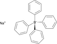
Chemical structure of sodium tetraphenylborate (NaBPh4).
Electrolyte solutions were prepared by dissolving NaBPh4 in DME in a dry Ar atmosphere. The ionic conductivities of NaBPh4/DME electrolytes at 25 °C are shown in Figure S1. The highest conductivity, 6.1 mS cm−1, was recorded at 0.5 mol dm−3 (m, molarity), which is comparable to that of a conventional 1.0 m NaPF6/ethylene carbonate (EC): diethyl carbonate (DEC) system (≈10 mS cm−1). Notably, even a dilute 0.1 m NaBPh4/DME system showed a high ionic conductivity of 2.7 mS cm−1 by virtue of the higher degree of salt dissociation than other salts (e.g., only 0.62 mS cm−1 for 0.1 m NaPF6/DME) (Figure S1).6 Hence, here, we mainly used 0.1 m NaBPh4/DME to control the electrolyte cost arising from NaBPh4. This electrolyte has an oxidation limit of ca. 3.4 V vs. Na/Na+ (Figure S2).
Na plating/stripping was studied in a Cu/Na half‐cell (Figure 1) at a constant current of 0.5 mA cm−2. Low CE (<20 %) and large polarization (>200 mV) were observed in a conventional 1.0 m NaPF6/EC:DEC electrolyte (Figure 1 a), suggesting that the interphase formed is unstable and highly resistive. In contrast, 0.1 m NaBPh4/DME showed both high CE (>97.5 % even in the first cycle) and low polarization (<10 mV) (Figure 1 b). Moreover, the increase in polarization was negligible over 100 cycles. Hence, a highly stable and low‐resistance interphase could be formed in NaBPh4/DME.
Figure 1.
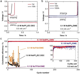
a,b) Charge‐discharge voltage curves of a Cu/Na cell with a) 1.0 m NaPF6/EC:DEC (1:1 by vol.) and b) 0.1 m NaBPh4/DME at 25 °C and a constant current of 0.5 mA cm−2. Na was plated on Cu for 1 h (corresponding to 0.5 mAh cm−2) and then stripped up to the cut‐off voltage of 0.5 V. c) Coulombic efficiencies (CEs) of Na plating/stripping in various electrolyte solutions under the same conditions as in Figure 1 (a)(b). The inset shows a comparison of the NaBPh4/DME and NaPF6/DME systems in the magnified vertical scale in which the solid lines denote the smoothed curves obtained with 10‐point adjacent averages.
To clarify the effect of the F‐free NaBPh4 salt, long‐term charge‐discharge tests were conducted in Cu/Na cells with various fluorinated salts (0.1 m) dissolved in DME (Figure 1 c). NaPF6/DME showed a high CE for 300 cycles, which is in agreement with the literature.2c However, another fluorinated salt electrolyte, NaFSA/DME, showed a low CE of <25 % on average for 50 cycles (Figure 1 c and Figure S3). In the cycled cell, we found a large amount of Na deposited on the Cu side even after stripping (Figure 2). For NaTFSA/DME, no stripping reaction was observed even in the first cycle (Figure 1 c and Figure S3). Hence, NaFSA and NaTFSA, although they are good F‐donors, are not effective in forming a stable interphase unless they are used at high concentrations.2f, 7 On the other hand, in 0.1 m NaBPh4/DME, the CE was 97.5 % in the first cycle and rapidly increased to >99.7 % after several cycles. The average CE was 99.85 % over 300 cycles (including the low‐efficiency first cycle). By analyzing the cycled Cu/Na cells (Figure 2), we found few Na deposits remaining on the Cu side after stripping, which also supports highly reversible Na plating/stripping. High reversibility was also achieved at various current densities (Figure S4) and salt concentrations (up to 0.7 m, which is close to the solubility limit of ca. 1 m) (Figure S5); for example, the average CE at 1.0 mA cm−2 for plating of 1.0 mAh cm−2 was 99.89 % over 200 cycles (Figure S4). Importantly, NaBPh4/DME resulted in higher CE (inset of Figure 1 c) and lower polarization (Figure 1 b and Figure S6) than the best combination of NaPF6/glyme previously reported.2c
Figure 2.
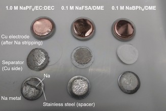
Cu electrode, separator, and Na metal in cycled Cu/Na cells with various electrolytes.
The cycling performance of Na metal electrodes was further evaluated in Na/Na symmetric cells (Figure 3 a). The conventional EC‐based electrolyte resulted in large polarization (≈100 mV) in the initial cycle, and it increased upon cycling. Hence, the EC‐based electrolyte could not form a stable interphase on the Na metal via its sacrificial reductive decomposition; the interphase could not suppress further electrolyte decomposition and thus continued to grow in thickness upon cycling. In contrast, the cell with NaBPh4/DME showed much lower polarization (≈10 mV) during cycling for over 500 h, suggesting the formation of a stable and low‐resistive interphase.
Figure 3.
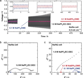
a) Charge‐discharge voltage profiles of Na/Na symmetric cells in the conventional electrolyte, 0.1 m NaPF6/DME, and 0.1 m NaBPh4/DME at 0.5 mA cm−2 and 25 °C. The profile after 450 h is shown only for 0.1 m NaBPh4/DME. The results of 0.1 m NaTFSA/DME and NaFSA/DME are not shown, because their voltage curves are so unstable and unreproducible. b) Impedance spectra of the Na/Na symmetric cells after one cycle at 25 °C. c) Magnified Figure of the impedance spectra.
Electrochemical impedance spectroscopy (EIS) of the Na/Na symmetric cells further demonstrated significantly decreased interfacial resistance in NaBPh4/DME (Figure 3bc). In the EC‐based electrolyte, the total interfacial resistance (SEI resistance and charge‐transfer resistance in the higher and lower frequency regions, respectively) was approximately 300 Ω, whereas that in NaBPh4/DME was only 3 Ω. Importantly, the interphasial resistance and the polarization were even lower than that with 0.1 m NaPF6/DME. These results indicate that an extremely stable and low‐resistivity interphase could be formed in NaBPh4/DME without using any fluorinated solvent or salt.
The morphology of plated Na was studied via scanning electron microscopy (SEM). The plated Na in 0.1 m NaBPh4/DME had a large nodule‐like structure with round‐shaped edges (Figure 4 a), which is similar to that in 0.1 m NaPF6/DME but is clearly different from that in 0.1 m NaFSA/DME (Figure S7). The large and round‐shaped Na has a low active surface area in contact with the electrolyte, which can minimize both electrolyte decomposition and dead (inactive) Na formation, leading to high CE.
Figure 4.
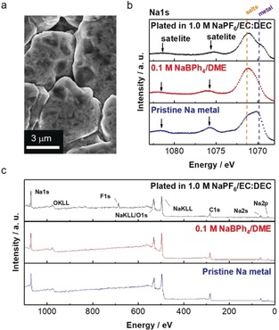
a) SEM image of the plated Na metal (corresponding to 0.5 mAh cm−2 at a constant current of 0.5 mA cm−2) on Cu in 0.1 m NaBPh4/DME. b) Na1s narrow‐scan and c) wide‐scan XPS spectra of the Na metal plated in various electrolyte solutions (conventional electrolyte and 0.1 m NaBPh4/DME) compared to pristine Na metal.
To obtain more insight into the high interfacial stability, we analyzed the SEI of Na metal via X‐ray photoelectron spectroscopy (XPS). Electrochemically plated Na metal on Cu was extracted from a Cu/Na cell in an Ar‐filled glovebox and then transferred into the XPS chamber without exposure to the air using a sealed transfer vessel. In the Na1s spectrum of pristine Na (Figure 4 b), plasmon satellites at 1076 eV and 1081 eV, which are characteristic of a metallic state, were observed. For the plated Na in conventional 1.0 m NaPF6/EC:DEC and 0.1 m NaBPh4/DME, these satellite peaks were still present, suggesting that the SEI layer was thin or that its coverage on the Na surface was incomplete. In the wide‐scan spectra of the Na metal in the conventional electrolyte (Figure 4 c), a sharp F1s peak at 684 eV, which is attributable to the formation of NaF, was observed; this NaF may work as an effective SEI component, as reported previously.2c In contrast, the plated Na in 0.1 m NaBPh4/DME exhibited almost the same spectrum as pristine Na. These results suggest that the active, metallic Na surface can be retained with minimized SEI formation in 0.1 m NaBPh4/DME, which is consistent with the significantly low interfacial resistance (Figure 3 c). The plated Na in 0.1 m NaPF6/DME showed a similar surface composition but with a small amount of F‐based compounds (Figure S8). If the Na was in contact with 0.1 m NaBPh4/DME for longer times (e.g., over 1 h), the plasmon satellites gradually diminished (Figure S9). Hence, we suppose that the reductive decomposition of 0.1 m NaBPh4/DME on Na metal is quite sluggish even with minimized SEI formation. Importantly, a negligible amount of F‐based compounds (only trace impurities) was found in the SEI. Hence, contrary to the conventional notion, a F‐rich SEI is not indispensable for stabilizing Na metal. Instead, the SEI is composed of C, O, and Na (Figure 4 c); specifically, C1s spectra (Figure S10) suggest the presence of the reduction products of DME (e.g., alkoxides). This very thin DME‐derived SEI is essentially stable and highly ion‐conductive, enabling highly reversible and rapid Na plating/stripping.
Another important finding is that there was a negligible amount of B‐based compounds in the SEI, suggesting that [BPh4]− was hardly decomposed on Na metal. On this basis, we suppose that the high reductive stability of the anion itself, rather than its passivation ability, is important for highly efficient Na plating/stripping. To demonstrate the negative effect of anion reduction, we studied the dual‐salt system of NaBPh4+NaFSA/DME (0.05 m+0.05 m). As shown in Figure S11, the CE of Na plating/stripping was significantly lower than that for NaBPh4/DME and was rather close to that for NaFSA/DME. This result suggests that the high CE with NaBPh4 is not mainly due to its good passivation (if its passivation were important, NaBPh4+NaFSA/DME would result in high CE close to that of NaBPh4/DME). Rather, the intrinsic reductive stability of the anion, as well as its SEI‐forming ability, is important for providing efficient Na metal electrodes.
Finally, we studied the origin of the high reductive stability of NaBPh4 by theoretical calculations. Table 1 shows electron affinities (EAs) of various anions in free (dissociated) and ion‐paired states evaluated by density functional theory (DFT) calculations. In a free state, [BPh4]− has the lowest EA, suggesting that it is energetically the most tolerant against reduction; this is consistent with the experimental fact. However, it should be noted that in reality, it is not a free anion but rather an ion‐paired anion that is preferentially reduced because the interaction with Na+ (a strong Lewis acid) would stabilize the anionic state. Here, we show that anions are most likely to form ion pairs with Na+ in DME (Figure 5 a) and that the EA of ion‐paired states accounts for the high reductive stability of NaBPh4/DME.
Table 1.
Electron affinities (EAs) for various anions in free and ion‐paired states [eV].
| Anion | EA (free) | EA (ion‐paired) |
|---|---|---|
| [BPh4]− | 0.2 (0.1[a]) | 1.2 (−0.0[a]) |
| PF6 − | 0.6 (1.1[a]) | 1.3 (1.7[a]) |
| [TFSA]− | 2.1[a] | 2.1[a] |
| [FSA]− | 2.9[a] | 3.5[a] |
[a] Values considering one‐electron reductive decomposition. It should also be noted that [BPh4]− and PF6 − form stable reduction species, i.e., [BPh4]2− (Na[BPh4]−) and PF6 2− (NaPF6 −), while [TFSA]− and [FSA]− are likely to decompose with an excess electron into N(SO2CF3)(SO2)− + CF3 − (NaCF3) and N(SO2F)(SO2)− + F− (NaF), respectively.
Figure 5.
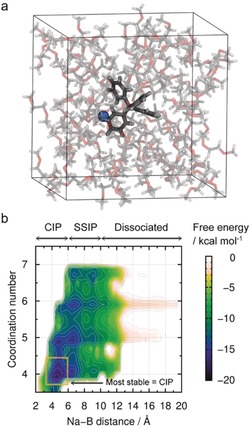
a) Representative snapshot of NaBPh4 and 94 DME (=0.1 m NaBPh4/DME) solution consisting of 1550 atoms. b) Two‐dimensional free energy surface for the ion‐pair distance and coordination number between Na and DME of NaBPh4/DME solution. The dissociation state at (16.0 Å, 6.0) is set to zero. Notably, such solvation and ion‐pair characteristics are difficult to analyze for dilute electrolytes via spectroscopies (Figure S14).
Based on the Walden plot (Figure S12), the degree of dissociation (ionicity scale) is only 0.15 for NaBPh4, although it is the highest among the salts studied. Hence, most anions (≈0.85 for [BPh4]− and more for others) are coordinated with Na+ even at a dilute concentration of 0.1 M. To identify its representative coordination state, we evaluated the two‐dimensional free energy surface with respect to various coordination states via DC‐DFTB‐metaD simulations (Figure 5 b).8, 9 The x‐axis shows the distance between Na+ and B in [BPh4]−, which corresponds to the ion‐pairing states, such as full dissociation, solvent‐separated ion pair (SSIP), or contact ion pair (CIP). The y‐axis shows the coordination number of Na+ with the oxygen atoms of DME. Based on this free energy surface, we found that the most stable state of [BPh4]− in 0.1 m NaBPh4/DME is CIP rather than SSIP or the fully dissociated state. The probability of CIP is approximately 0.9 based on the Boltzmann distribution, which is in good agreement with the degree of dissociation (0.15) obtained by the Walden plot. A similar probability of CIP was obtained for 0.1 m NaFSA/DME (Figure S13). As a result, it is reasonable to compare the reductive stability of anions in their ion‐paired states.
The EAs of Na+ ion‐paired anions are summarized in Table 1. For most anions, the EAs increase upon pairing with Na+ as a result of partial electron donation (anion → Na+). However, it is notable that ion‐paired [BPh4]− has the lowest EA among all anions. The present result suggests that [BPh4]− is energetically the most tolerant against reduction, which accounts for the stable Na/electrolyte interphase. Furthermore, the order of EAs ([BPh4]− ≤ PF6 − ≪ [TFSA]− < [FSA]−) agrees well with the CEs of Na plating/stripping (Figure 1 c). This work demonstrates that the cation‐anion interaction and relevant change of the anion's reductive stability are important in designing highly stable electrolytes for Na metal electrodes.
In conclusion, we have discovered a F‐free NaBPh4/DME electrolyte that enables stable and efficient Na plating/stripping with an average CE of 99.85 % over 300 cycles, which is comparable to the best one reported for a particular fluorinated electrolyte (NaPF6/glyme)2c under similar conditions (Table S2). Importantly, the electrolyte can form a stable, thin, and low‐resistivity SEI derived from DME (composed mainly of C, O, and Na), suggesting that contrary to the conventional notion, a F‐rich SEI is not indispensable for reversible Na plating/stripping. Experimental and calculation results demonstrate that the intrinsic reductive stability of ion‐paired salts is rather more important than their F‐donating ability. The present work, presenting a new strategy to stabilize Na metal electrodes without using a fluorinated salt or solvent, will further promote research on F‐free electrolytes for eco‐friendly, cheap, and high‐energy‐density batteries.
Conflict of interest
The authors declare no conflict of interest.
Supporting information
As a service to our authors and readers, this journal provides supporting information supplied by the authors. Such materials are peer reviewed and may be re‐organized for online delivery, but are not copy‐edited or typeset. Technical support issues arising from supporting information (other than missing files) should be addressed to the authors.
Supplementary
Acknowledgements
This work was supported by the Elements Strategy Initiative for Catalysts & Batteries (ESICB) of the Ministry of Education, Culture, Sports, Science and Technology (MEXT). Some of the present calculations were performed at the Research Center for Computational Science (RCCS), Okazaki Research Facilities, National Institutes of Natural Sciences (NINS).
K. Doi, Y. Yamada, M. Okoshi, J. Ono, C.-P. Chou, H. Nakai, A. Yamada, Angew. Chem. Int. Ed. 2019, 58, 8024.
References
- 1. Xu K., Chem. Rev. 2014, 114, 11503–11618. [DOI] [PubMed] [Google Scholar]
- 2.
- 2a. Kanamura K., Shiraishi S., Takehara Z., J. Electrochem. Soc. 1996, 143, 2187; [Google Scholar]
- 2b. Komaba S., Ishikawa T., Yabuuchi N., Murata W., Ito A., Ohsawa Y., ACS Appl. Mater. Interfaces 2011, 3, 4165–4168; [DOI] [PubMed] [Google Scholar]
- 2c. Seh Z. W., Sun J., Sun Y., Cui Y., ACS Cent. Sci. 2015, 1, 449–455; [DOI] [PMC free article] [PubMed] [Google Scholar]
- 2d. Choudhury S., Archer L. A., Adv. Electron. Mater. 2016, 2, 1500246; [Google Scholar]
- 2e. Zhang X.-Q., Cheng X.-B., Chen X., Yan C., Zhang Q., Adv. Funct. Mater. 2017, 27, 1605989; [Google Scholar]
- 2f. Zheng J., Chen S., Zhao W., Song J., Engelhard M. H., Zhang J.-G., ACS Energy Lett. 2018, 3, 315–321; [Google Scholar]
- 2g. Fan X., Chen L., Ji X., Deng T., Hou S., Chen J., Zheng J., Wang F., Jiang J., Xu K., et al., Chem 2018, 4, 174–185; [Google Scholar]
- 2h. Suo L., Xue W., Gobet M., Greenbaum S. G., Wang C., Chen Y., Yang W., Li Y., Li J., Proc. Natl. Acad. Sci. USA 2018, 115, 1156–1161. [DOI] [PMC free article] [PubMed] [Google Scholar]
- 3. Liu H., Wang X., Zhou H., Lim H.-D., Xing X., Yan Q., Meng Y. S., Liu P., ACS Appl. Energy Mater. 2018, 1, 1864–1869. [Google Scholar]
- 4.
- 4a. Yamada Y., Furukawa K., Sodeyama K., Kikuchi K., Yaegashi M., Tateyama Y., Yamada A., J. Am. Chem. Soc. 2014, 136, 5039–5046; [DOI] [PubMed] [Google Scholar]
- 4b. Suo L., Borodin O., Gao T., Olguin M., Ho J., Fan X., Luo C., Wang C., Xu K., Science 2015, 350, 938–943; [DOI] [PubMed] [Google Scholar]
- 4c. Suo L., Borodin O., Wang Y., Rong X., Sun W., Fan X., Xu S., Schroeder M. A., Cresce A. V., Wang F., et al., Adv. Energy Mater. 2017, 7, 1701189; [Google Scholar]
- 4d. Wang J., Yamada Y., Sodeyama K., Watanabe E., Takada K., Tateyama Y., Yamada A., Nat. Energy 2018, 3, 22–29. [Google Scholar]
- 5. Scheers J., Lim D.-H., Kim J.-K., Paillard E., Henderson W. A., Johansson P., Ahn J.-H., Jacobsson P., J. Power Sources 2014, 251, 451–458. [Google Scholar]
- 6.
- 6a. Henderson W. A., Brooks N. R., Brennessel W. W., Young V. G., Chem. Mater. 2003, 15, 4679–4684; [Google Scholar]
- 6b. Jónsson E., Johansson P., Phys. Chem. Chem. Phys. 2012, 14, 10774–10779. [DOI] [PubMed] [Google Scholar]
- 7.
- 7a. He M., Lau K. C., Ren X., Xiao N., McCulloch W. D., Curtiss L. A., Wu Y., Angew. Chem. Int. Ed. 2016, 55, 15310–15314; [DOI] [PubMed] [Google Scholar]
- 7b. Cao R., Mishra K., Li X., Qian J., Engelhard M. H., Bowden M. E., Han K. S., Mueller K. T., Henderson W. A., Zhang J.-G., Nano Energy 2016, 30, 825–830; [Google Scholar]
- 7c. Lee J., Lee Y., Lee J., Lee S.-M., Choi J.-H., Kim H., Kwon M.-S., Kang K., Lee K. T., Choi N.-S., ACS Appl. Mater. Interfaces 2017, 9, 3723–3732; [DOI] [PubMed] [Google Scholar]
- 7d. Schafzahl L., Hanzu I., Wilkening M., Freunberger S. A., ChemSusChem 2017, 10, 401–408. [DOI] [PubMed] [Google Scholar]
- 8.
- 8a. Nishizawa H., Nishimura Y., Kobayashi M., Irle S., Nakai H., J. Comput. Chem. 2016, 37, 1983–1992; [DOI] [PubMed] [Google Scholar]
- 8b. Nishimura Y., Nakai H., J. Comput. Chem. 2018, 39, 105–116. [DOI] [PubMed] [Google Scholar]
- 9. Barducci A., Bussi G., Parrinello M., Phys. Rev. Lett. 2008, 100, 20603. [DOI] [PubMed] [Google Scholar]
Associated Data
This section collects any data citations, data availability statements, or supplementary materials included in this article.
Supplementary Materials
As a service to our authors and readers, this journal provides supporting information supplied by the authors. Such materials are peer reviewed and may be re‐organized for online delivery, but are not copy‐edited or typeset. Technical support issues arising from supporting information (other than missing files) should be addressed to the authors.
Supplementary


