Abstract
Earlier work on RF metasurfaces for preclinical MRI has targeted applications such as whole‐body imaging and dual‐frequency coils. In these studies, a nonresonant loop was used to induce currents into a metasurface that was operated as a passive inductively powered resonator. However, as we show in this study, the strategy of using a resonant metasurface reduces the impact of the loop on the global performance of the assembled coil. To mitigate this deficiency, we developed a new approach that relies on the combination of a commercial surface coil and a coupled‐wire structure operated away from its resonance. This strategy enables the extension of the sensitive volume of the surface coil while maintaining its local high sensitivity without any hardware modification. A wireless coil based on a two parallel coupled‐wire structure was designed and electromagnetic field simulations were carried out with different levels of matching and coupling between both components of the coil. For experimental characterization, a prototype was built and tested at two frequencies, 300 MHz for 1H and 282.6 MHz for 19F at 7 T. Phantom and in vivo MRI experiments were conducted in different configurations to study signal and noise figures of the structure. The results showed that the proposed strategy improves the overall sensitive volume while simultaneously maintaining a high signal‐to‐noise ratio (SNR). Metasurfaces based on coupled wires are therefore shown here as promising and versatile elements in the MRI RF chain, as they allow customized adjustment of the sensitive volume as a function of SNR yield. In addition, they can be easily adapted to different Larmor frequencies without loss of performance.
Keywords: 19F MRI, computational electromagnetics, metamaterials, metasurface, RF coils, whole‐body imaging
Abbreviations used
- FA
flip angle
- FID
free induction decay
- FLASH
fast low‐angle shot
- FOV
field of view
- NA
number of averages
- RARE
rapid imaging with refocused echoes
- SNR
signal‐to‐noise ratio
- VNA
vector network analyzer
1. INTRODUCTION
In clinical and preclinical magnetic resonance imaging (MRI), the commonly used radiofrequency (RF) coils belong to one of two categories, volume or surface coils.
Volume coils such as birdcage coils1, 2 provide a uniform B1 + magnetic field in large volumes. However, when a birdcage coil is used for both transmission and reception of the RF field, it provides relatively low sensitivity and therefore poor signal‐to‐noise ratio (SNR)3 as the subject under study is usually far from any conducting element to ensure the homogeneity of the magnetic field. On the other hand, small surface coils usually implemented as flat copper loops, due to their superior sensitivity, can provide high SNR,4 but with the main drawback that the B1 + magnetic field decays in depth as 1/ , where R is the radius of the loop and d is the distance from the loop plane.5 Consequently, the high efficiency of small surface coils is only available in a small area close to the coil. Currently, the most effective and established solution is the use of surface coil arrays to extend the in‐plane coverage while keeping SNR high.6 However, surface arrays require multi‐channel drivers and in most cases they are only used for signal reception. They also require specific element‐wise signal recombination procedures,7 which are not trivial when phase‐sensitive information is to be kept in the final image or spectrum. Finally, phased arrays are also more complicated to use for RF transmission, especially for localized spectroscopy.8
Recently, metamaterial‐inspired RF coils have been developed to bring more flexibility into the design of MRI coils for preclinical imaging. First, a volume coil based on hybridized wires was proposed.9 Later on, metasurfaces based on a parallel array of inductively coupled wires were explored. These wire arrays also rely on the hybridization mechanism10 in order to obtain a homogeneous B1 + magnetic field. To do so, the wires used need to be either of a resonant length10 or miniaturized by high‐permittivity loading,11 or by capacitive interconnections.12 These studies demonstrate the possibility of using such metasurface structures to achieve a dual‐frequency coil for proton and fluorine imaging,13 and a coil for whole‐body imaging with higher SNR than a volume coil.14
It has been shown that the optimal impedance matching of such metasurface‐based coils is obtained with a nonresonant feed loop when one of the metasurface resonances coincides with the targeted Larmor frequency. This configuration offered the best compromise between large sensitive volume and high SNR in shallow depth.14 However, the highest local SNR was still obtained with a small matched surface coil.5 The objective of this work was to explore whether advantages can be obtained by combining metasurfaces and resonant surface coil. Due to mutual coupling, however, the simple combination of a resonant metasurface with a small matched loop would lead to a shift of both resonances away from their original resonance frequency.15 This mutual coupling was previously observed and exploited to obtain increased field penetration from two concentric surface loops16 and to build a volume coil from four inducted loops.17 We assessed the mutual coupling in our specific hybridized wire configuration by studying amplitude and phase of currents in the loop and the coupled‐wire structure.
For this purpose, we designed, simulated and built an elementary structure with two parallel wires of the same length.18 This is the minimum number of wires enabling excitation of a mode with currents flowing in opposite directions in the wires. This mode behaves similarly to a long loop and allows a large coverage in the plane of the structure. The structure was studied numerically and experimentally on a 7 T preclinical scanner to verify its potential advantages over existing solutions. Namely, we hypothesized that beyond their use in a resonant regime, coupled‐wire structures can be used away from their natural resonances and can be combined with a commercial surface coil instead of a nonresonant feed loop to achieve a significant improvement of sensitive volume while maintaining a high efficiency over the surface coil area. We further explored the feasibility of 19F MRI with the same structure on a phantom and in mice in vivo.
2. MATERIALS AND METHODS
2.1. Numerical study
Three configurations were numerically studied (Figure 1) using CST Microwave Studio 2017 (Computer Simulation Technology GmbH, Darmstadt, Germany): (case A) a surface loop tuned and matched with two lumped capacitors; (case B) a resonant coupled‐wire structure with two wires of length L0 coupled to a nonmatched feed loop; and (case C) a detuned coupled‐wire structure with variable wire length L combined with a matched loop.
Figure 1.
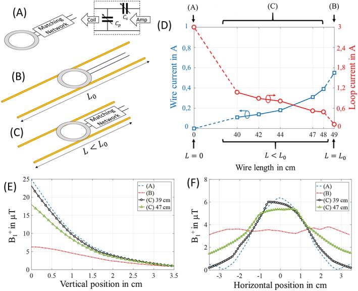
Numerical analysis of the three configurations: Sketch of (A) surface coil with a matching circuit, (B) resonant coupled‐wire coil conformed by two wires with length L0 (49 cm) coupled with an unmatched feed loop and (C) nonresonant coupled‐wire coil that combines a matched surface coil with two wires of length L smaller than the resonant length L0. The diameter of the loop in all cases is 3 cm and the wires are 3 cm apart. (D) Shows the plot of the current amplitudes in the loop (red) and in the wires (blue) with the different configurations. In each of the configurations the coil was tuned and matched to 300 MHz, and 1 W of input power was used. (E) Shows the B1 + profiles obtained in the phantom along a vertical line through the center of coils (A), (B) and (C) with 39 cm and 47 cm. (F) Shows B1 + evaluated in the phantom on a horizontal line along the wires at 1.2 cm from the bottom surface of the phantom
All results were obtained at a frequency of 300 MHz (Larmor frequency of 1H at 7 T). In all cases, the loop had a diameter of 3 cm, and the input power used was 1 W. In the coupled‐wire based coils, the wires were 3 cm apart, parallel to the MRI bore axis, and the loop used was placed above the wires at a distance of 1 mm and centered at the median position of the wire length. The material used for wires and loop was copper. Simulations were carried out in the presence of a homogeneous phantom of 35 x 35 x 70 mm3 with a relative dielectric permittivity (ε) of 50 and a conductivity (σ) of 0.98 S/m. The RF shield was simulated using a copper tube with 1000 mm length and 100 mm internal diameter.
In case A (Figure 1A), tuning and matching of the surface coil was achieved with a matching network. In case B (Figure 1B), impedance matching was obtained with a short separation (1 mm) between the loop and the wire plane. The resonance of the coupled‐wire structure was tuned to 300 MHz by adjusting the wire length to L0, close to a half wavelength (≈50 cm). The last case, case C (Figure 1C), required both surface coil and coupled wires to be detuned from the Larmor frequency to correctly tune the whole coil structure. Different wire lengths were considered, while keeping L < L0 in order to shift the coupled‐wire resonances to a higher frequency. We will name this configuration the “nonresonant regime” as the wires are operated away from their natural resonance frequency, in contrast to the “resonant regime” in which the resonance frequency of the wires coincides with the Larmor frequency. For each length, the capacitor values of the surface coil's matching circuit were adapted to reach impedance matching at the Larmor frequency. The maximum amplitude current in the loop and in the wires was evaluated in all cases as a function of wire length (Figure 1D). Finally, the spatial B1 + amplitude profiles were obtained inside the phantom volume along the vertical axis in the center of the structure (Figure 1E) and parallel to the wires' length at 1.2 cm depth (Figure 1F).
2.2. Coil setups
Three different coil setups were compared as single channel transmit‐receive antenna for proton and fluorine imaging: (case A) a 30 mm diameter commercial surface coil (Bruker 1H‐19F, model 1P T957 8 V); (case B) the resonant coupled‐wire structure combined with a printed feed loop; and (case C) the nonresonant coupled‐wire structure combined with the commercial surface loop. A 70 mm diameter commercial 1H birdcage coil (Bruker Biospin, Ettlingen, Germany) was included in the tests as an additional reference, but only allowed proton imaging.
A prototype of the simulated coupled‐wire structure was built using two telescopic brass tubes.19 The wires were separated by 3 cm and placed on a plastic board of 2 mm thickness (Figure 2D). Their length (L) was adjustable to tune the resonance to the desired frequency. Both wires had the same length at the end of each tuning procedure.
Figure 2.
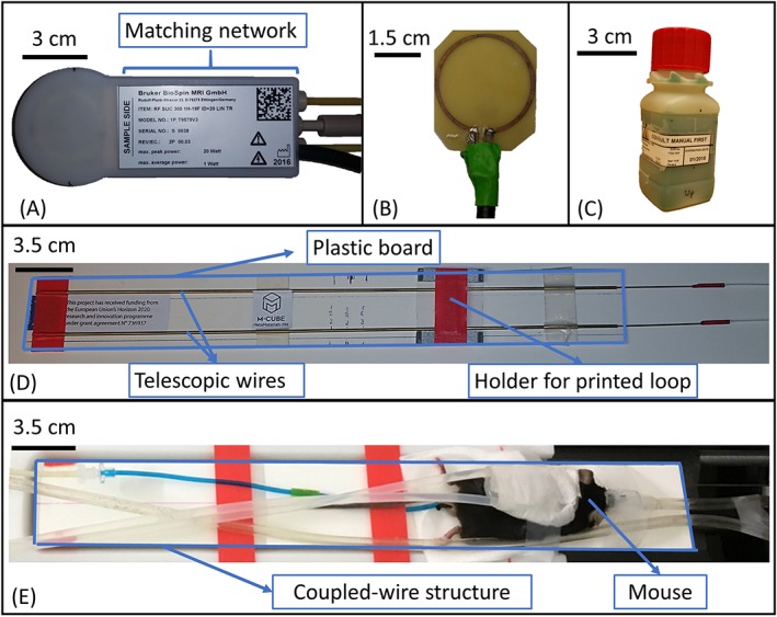
Coupled‐wire inspired coil for 7 T small animal imaging: (A) picture of the commercial surface coil (Bruker, model 1P T957 8 V); (B) picture of the printed loop of 3 cm diameter on circuit board (FR‐4, 0.5 mm thickness) and fed through a coaxial cable; (C) Bruker 19F/1H phantom of 3.5 x 3.5 x 9 cm3 used during on‐bench measurements and MRI scans, concentration of 19F of 100 mmol/L; (D) picture of the coupled‐wire structure with two telescopic wires separated by 3 cm and placed on a plastic board; (E) picture of the in vivo experimental setup
To build the resonant coupled‐wire coil (case B), an unmatched copper loop of 3 cm diameter was printed on a 0.5 mm thick FR‐4 circuit board which had an ε = 4.4 and a σ = 0.02 S/m (Figure 2B). The loop was fed by a coaxial cable. The matching of this coil relied on the symmetry and the distance between loop and wires. Tuning for both frequencies (300 MHz for 1H or 282.6 MHz for 19F) was achieved by adjusting the length of the wires to L0 at which the coupled wires resonate at the Larmor frequency.
To reproduce the nonresonant coupled‐wire coil (case C), a commercial surface coil of 3 cm diameter (Bruker 1H‐19F, model 1P T957 8 V) (Figure 2A) was used in combination with the described coupled‐wire structure. This coil is single resonant with a frequency switching network that allowed measurements for 1H and 19F. The coil's matching circuit was used for final tuning and matching at both frequencies. This only required an adjustment of the wire length L such that L < L0 to allow the redistribution of currents in the coil structure.
On‐bench measurements of the reflection coefficient were conducted for the resonant coupled‐wire coil (case B) for different loading samples using a vector network analyzer (VNA MS2036C, Anritsu, Kanagawa, Japan) to ensure proper tuning and impedance matching for both frequencies. On‐bench measurements could not be performed for the other configurations as commercial coils could not be interfaced with the VNA.
2.3. Phantom experiments
Validation of the experimental coils was performed using a PharmaScan 7 T MR system (Bruker Biospin) running ParaVision 6.0.1 software. The phantom used contained a small volume fraction of 2–2‐trifluoroethanol leading to a concentration of 19F nuclei in the order of 100 mmol/L (Figure 2C). The dimensions of the phantom are 35 x 35 x 90 mm3. The phantom was placed horizontally, parallel to the MRI bore axis, on the center of the corresponding coil.
For every tested coil, a fast low‐angle shot (FLASH) localizer sequence was used after wobble, iterative shimming and frequency adjustment. No parallel imaging aspects were used. No filtering, distortion correction, thresholding, or low‐dynamic‐range image conversion took place. After Fourier Transform carried out on 32‐bit floating‐point arrays, the images were stored as 16‐bit unsigned integer arrays.
Using the coronal slice from the localizer series, the reference power was adjusted automatically (Spin Echo/stimulated echo comparison/iteration) in a slab positioned directly adjacent to the coil surface, except for the birdcage coil, for which the reference power was adjusted without volume selection.
Single slice FLASH sequences were run in the three orientations to obtain 1H images of the phantom. The parameters of the sequence were: TE/TR = 2.54/500 ms, number of averages (NA) = 1, flip angle (FA) α = 60°, slice thickness = 0.9 mm, in‐plane spatial resolution = 0.7 x 0.7 mm2 and field of view (FOV) = 9 x 9 cm2 with a total acquisition time of one minute, four seconds. SNR maps were obtained from the proton images using MATLAB (MathWorks, Natick, MA). Noise was calculated as the standard deviation of pixel values in a region of interest (ROI) in the lower left corner of the image where residual signal is absent. The SNR maps were calculated as the ratio of each voxel signal over the noise value of the image.
After tuning to the 19F frequency, a single pulse FID sequence (TR = 3000 ms, spectral bandwidth = 7 kHz, number of points = 2048, NA = 4) was used to obtain the exact resonance frequency of 2–2‐trifluoroethanol (offset –21636 Hz). 19F images were acquired with a T2‐TurboRARE‐3D sequence with effective TE = 68.22 ms, TE interval = 4.55 ms, TR = 3000 ms, RARE factor = 32, NA = 1, slice thickness = 40 mm, matrix = 64 x 64 x 32 (in‐plane spatial resolution = 1 x 1 mm2), FOV = 6 x 6 cm2 and a total acquisition time of 20 minutes. Fluorine images were processed in MATLAB to overlay them on 1H FLASH images using a transparency of 0.6, where 0 is completely transparent and 1 is opaque.
2.4. In vivo MRI experiments
In vivo validation was performed using the same coil setups. All experiments were conducted according to a protocol approved by the Aix Marseille University's animal experimentation committee (APAFIS#10547–2017071009112930 v4). Three C57Bl6 mice (aged nine weeks) were used for this in vivo demonstration. Mice were anesthetized with 3% isoflurane (CF3CH2ClOCHF2) in an induction chamber. The animals were held under anesthesia using 1.5–1.7% isoflurane in a stream of 1 L/min room air administered through a face mask. They were placed in prone position with the abdominal region in the center of the corresponding coil (Figure 2E). Great care was taken to reproduce the same position across the different coil setups tested. Postprocessing of the 1H and 19F images was similar to the phantom study. For this study, no ECG gating was used. Based on previous experiments in which temperature was monitored, the warm‐water heating blanket placed on the back of the mouse was adjusted to 40°C to ensure the animal's body temperature in the physiologic range. No body temperature probe was used during these experiments. The only physiological monitoring performed during in vivo experiments consisted of the respiration using a pressure sensor connected to an air‐filled balloon positioned under the abdomen of the mouse.
The 2D FLASH sequence used for proton imaging had the following parameters: TE/TR = 2.23/50 ms, NA = 8, FA α = 30°, slice thickness = 0.9 mm, in‐plane spatial resolution = 0.23 x 0.23 mm2, FOV = 6 x 6 cm2 and a total acquisition time of two minutes.
Despite negligible natural endogenous fluorine concentrations in the body,20 19F imaging of the mouse abdomen in vivo was possible by using the signal of isoflurane, used here as anesthetic. Isoflurane is indeed known to accumulate in certain lipid compartments in anesthetized animals as shown in a recent study.21 19F spectroscopy was conducted using a single pulse FID sequence with TR = 3000 ms, spectral bandwidth = 7 kHz, number of points = 2048, NA = 20 and frequency offset = −23537 Hz. 19F imaging was performed using a FLASH sequence with TE/TR = 2.23/800 ms, NA = 32, FA α = 90°, slice thickness = 3.9 mm, in‐plane spatial resolution = 1.8 x 1.8 mm2, frequency offset = −23537 Hz, FOV = 6 x 6 cm2 and a total acquisition time of 13 minutes.
3. RESULTS
3.1. Numerical study
In Figure 1D, the maximum current in the loop (red curve) and in the coupled‐wire structure (blue curve) are plotted. The current in the loop was taken at the feed point as its amplitude remains almost constant due to the loop's small diameter. We monitored the wire currents in the center of the wire length where the current amplitude was maximal. As expected from previous work, in case B, the current in the loop is very low as the loop is nonmatched. With the wires getting shorter (L < L0), the resonance of the coupled wires shifted. Note that this change was compensated for each value of L by adjusting the capacity in the matching circuit at the loop's input. Nonetheless, the maximum current in the wires decayed continuously as the wire length was reduced.
Figure 1E shows that the maximum B1 + magnitude depends mainly on the loop current; it was maximal for case A and minimal for case B. On the other hand, the horizontal extension of the FOV was linked to the current amplitude in the wires. The nonresonant behavior, case C, allowed us to simultaneously obtain a large sensitivity near the loop while still benefiting from the increased B1 + extent from the wires. Two different wire lengths (39 and 47 cm) were presented for case C and each showed a different distribution of B1 + due to different contributions from the loop and the wires.
3.2. Coil setups
With the VNA measurements, it was found that the optimal length L0 of the wires in case B without any sample load was 49.5 cm for 1H (300 MHz) and 52.5 cm for 19F (282.6 MHz), which in both cases corresponds approximately to a half wavelength in air. The phantom and a mouse were used to test the behavior of the coil with different loads. The level of impedance matching is slightly perturbed but remains below −25 dB (Figure 3). A small reduction of the wire length (5 mm) was enough to compensate the frequency shift due to each load.
Figure 3.
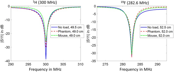
|S11| on‐bench measurements of case B without load, with the phantom and with a mouse at 1H and 19F Larmor frequencies
In cases A and C, the commercial surface coil could not be directly connected to the VNA and therefore tuning could only be carried out in the scanner. For case C, a wire length of 39.0 cm was used for both nuclei, 19F and 1H, as the limit of tuning/matching circuit capabilities of the Bruker surface coil was reached. Nevertheless, tuning and matching of the assembled coil was good enough to perform MRI experiments.
3.3. Phantom MRI experiments
Table 1 shows the reference power values (the power required to reach a flip angle of 90° with a 1 ms pulse) obtained on the scanner for each coil with the phantom located in the center of the coil (center of wires and loop aligned). As expected, the birdcage coil required higher power than the other coils (3.89 W). The surface coil required the lowest power (0.14 W). Note that in case C the reference power (0.22 W) was comparable with that of the surface coil alone.
Table 1.
Analysis of 1H results. The reference powers obtained for the different coils after RF autocalibration of the magnet, the average standard deviation of noise calculated from both coronal and sagittal images, and the comparison of the FOV and SNR obtained from each coil
| Coil | Reference power (W) | Average σ | FOV and SNR |
|---|---|---|---|
| Birdcage coil | 3.89 | 1.55 e−5 | Whole‐body with homogeneous and low SNR (100) |
| Case B | 0.96 | 1.35 e−5 | Whole‐body with higher SNR (250) in shallow depth |
| Surface coil | 0.14 | 1.35 e−5 | Reduced FOV with high SNR (1200) |
| Case C | 0.22 | 1.21 e−5 | Wider FOV with a local SNR (900) |
SNR maps and profiles for every coil tested with the phantom are presented in Figures 4 and 5. Figure 5A,B shows that there was almost a 4‐fold ratio in SNR between birdcage coil/case B and surface coil/case C at 5 mm depth inside the phantom. Figure 5E shows that up until 8 mm depth, the birdcage coil produced the lowest SNR, although it was the most homogeneous in all orientations. Case B (Figure 4B,F,J) provided a large homogeneous imaging FOV comparable with that of the birdcage coil. However, SNR gets lower than the birdcage coil at a depth of 8 mm (Figure 5C,D). For case C (Figure 4C,G,K), a large enhancement of the SNR of 3.5‐fold was encountered at the loop location compared with case B, as predicted from the numerical analysis above. When compared with the surface coil alone at 5 mm depth (Figure 5A,B), case C presents a reduction in SNR of 20%. However, we observed that the FOV was enlarged in the coronal‐sagittal profile (Figure 5A), giving access to areas invisible with the surface coil. For a deeper observation plane (Figure 5C,D), case C provided identical maximum SNR, but still offers a wider visible volume compared with the surface coil alone.
Figure 4.
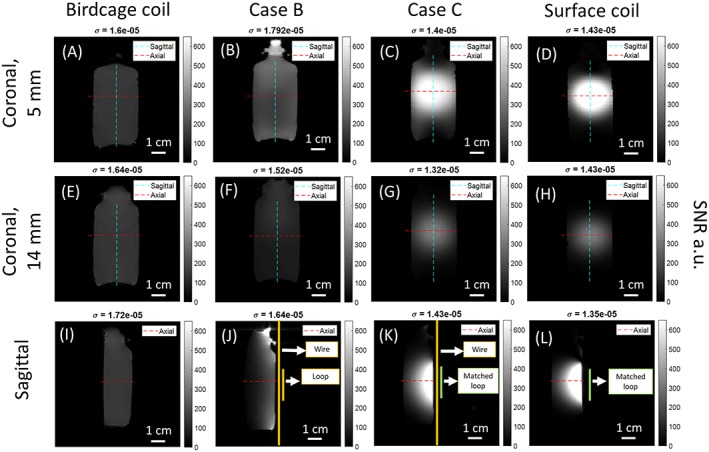
Coronal slices at depths of 5 mm and 14 mm from the edge of the phantom close to the coils and sagittal SNR maps in gray scale (dashed lines locate the profile cuts). (A), (E), (I): Birdcage coil; (B), (F), (J): Case B; (C), (G), (K): Case C; (D), (H), (L): Surface coil. In the coronal slices, the cyan line gives the coronal‐sagittal profiles; the red line gives the coronal‐axial profiles. In the sagittal slices, the red line gives the axial‐coronal profiles. Noise standard deviation is given at the top of each map
Figure 5.
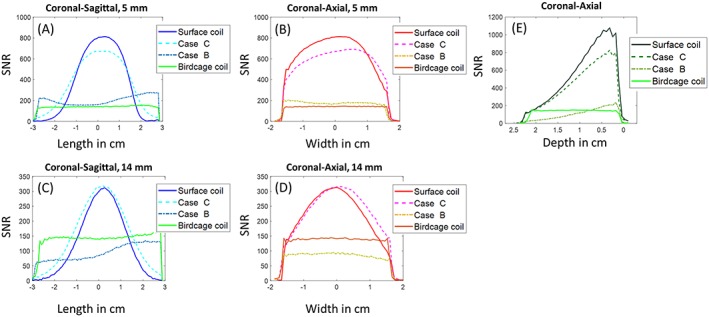
SNR profiles of the proton images. (A) and (C) show the coronal‐sagittal profiles at depths of 5 mm and 14 mm from the edge of the phantom close to the coils, respectively; (B) and (D) show the coronal‐axial profiles in the center of the phantom; (E) shows the sagittal‐axial profiles
19F images are presented in Figure 6. It can be seen that the coils present the same signal distribution as for proton imaging. The noise in these images is considerable, and the present low spatial resolution due to the weak concentration of 19F nuclei in the phantom make it difficult to obtain reliable SNR measurements. Nonetheless, Figure 6 confirms that the SNR provided by the two coupled‐wire coils (cases B and C) was sufficient to produce a 3D 19F image from a diluted phantom within 20 minutes.
Figure 6.
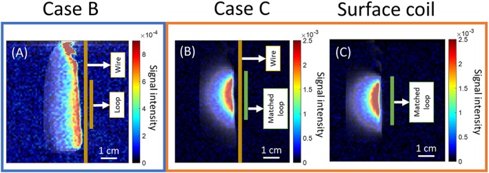
19F T2‐turboRARE‐3D image in jet color map acquired with: (A) case B, (B) case C and (C) surface coil in sagittal orientation. Because of the different sensitivities, the color scale is modified between map (A), and maps (B) and (C). The images were overlaid on top of 1H FLASH images in gray scale
3.4. In vivo MRI experiments
Figure 7 presents the results obtained for the mouse proton MRI experiments. The behavior of the different coil setups remains consistent with the previous phantom study. Similar to the phantom study, it is observed that the birdcage coil has low and homogeneous SNR. Case B yielded higher SNR near the wires than the birdcage coil (Figure 7A,B). This is confirmed by results presented in Table 2, which focuses on SNR values obtained in the heart (square ROIs denoted in Figure 7) for coronal slices (6.3 mm depth). Table 2 shows that case B provides 30% better SNR compared with the birdcage coil in that slice.
Figure 7.
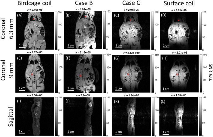
In vivo 1H SNR maps. Coronal and sagittal plane images with: (A), (E), (I): Birdcage coil; (B), (F), (J): Case B; (C), (G), (K): Case C; and (D), (H), (L): Surface coil. The red boxes indicate the two ROIs used for the results in Table 2
Table 2.
Analysis of 1H in vivo results. Mean SNR of the ROIs from the heart at a depth of 6.3 mm and the muscle at a depth of 9 mm
| Coil | SNR of the heart at 6.3 mm depth | SNR of the muscle at 9 mm depth |
|---|---|---|
| Birdcage coil | 66.43 +/− 10.43 | 87.34 +/− 13.70 |
| Case B | 92.74 +/− 7.32 | 49.18 +/− 6.61 |
| Surface coil | 16.89 +/− 3.65 | 112.50 +/− 3.42 |
| Case C | 41.27 +/− 6.78 | 91.67 +/− 3.64 |
Once again, the surface coil (Figure 7D,H,L) provided the highest SNR but the smallest FOV compared with case C. Table 2 confirms the FOV extension obtained with case C as the SNR measured in the heart (away from the loop center) increased 2.5‐fold. At the same time, the SNR values were preserved close to the loop in the center of the FOV. This is observed for the deeper slice (9 mm depth) and confirmed by the SNR value in Table 2 where surface coil and case C showed a similar value.
For fluorine, it was found that the Larmor frequency of 19F nuclei in isoflurane was 282.577 MHz. Images and spectra are shown in Figure 8. Measured 19F spectra for all cases showed that we detected the presence of accumulated isoflurane inside the mouse. In case B, the measured signal was comparable with the noise level, making analysis more difficult with the given scan parameters (Figure 8A). We can see that case C and the surface coil provided sufficient sensitivity to enable a clear localization of isoflurane with the given scan parameters (Figure 8B,C).
Figure 8.
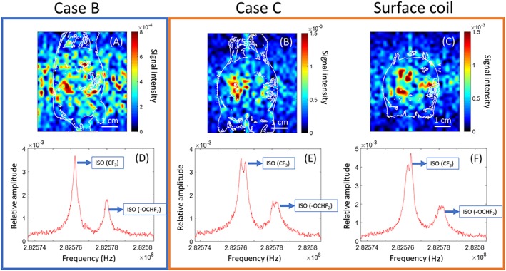
Top: In vivo 19F FLASH coronal‐plane images in jet scale obtained with: (A) case B; (B) case C; and (C) surface coil. Because of the different sensitivities, the color scale is modified between map (A), and maps (B) and (C). The images were overlaid with 1H FLASH contour plot (white lines) to illustrate the anatomical location of 19F nuclei. Bottom: In vivo 19F spectra for each case. The two peaks which are labeled correspond to two fluorinated groups of the isoflurane molecule
4. DISCUSSION
Previously reported numerical studies of the sensitivity of coupled‐wire coils show that when a resonant length is used (case B), coil performance is dominated by the wires. In this case, the current in the loop is extremely low, and consequently a low amplitude B1 + field is generated. On the contrary, the current along the wires is almost constant leading to a wide FOV.22 This explains why B1 + remains almost constant along the wires (Figure 1F). A simple approach to benefit from both the loop's and the wire's maximum contributions would be to place the resonant coupled‐wire structure on top of a loop matched with lumped capacitors. However, this option would not actually work because the interaction of the two resonant parts would inevitably affect both resonances due to strong inductive coupling. This usually leads to two hybrid resonances, which shifts the frequencies away from the initially targeted frequency.23, 24 Our results show that we were able to combine the coupled‐wire structure and the matched loop by tuning the wire's resonance away from the Larmor frequency together with a small adjustment in the surface coil's matching circuit.
By using a nonresonant coupled‐wire structure with adjustable wire length coupled to a matched loop (case C), a strong increase in the loop current could be clearly observed. The main benefit is that the length of the wires can be adapted to rearrange the distribution of currents within the different parts of the coil (loop and wires). The fact that the current in the wires dropped slowly as the wire length became shorter (blue curve in Figure 1D) allowed us to benefit from both contributions (wire and loop) when using such a configuration. More details concerning the phase delay between wire and loop currents are presented in Figure S2. This benefit can be observed more clearly in the B1 + profile of case C with a wire length of 47.0 cm (simulation size) (Figure 1E,F), where a strong increase in sensitivity at the loop position can be observed while maintaining (on average) 75% of the sensitivity along the wires. This redistribution of currents has a significant impact on the sensitivity and the FOV which can be achieved by the coil. Moreover, the relative contribution of the wire and the loop can be modulated via the detuning of the coupled‐wire structure. Figure 1E,F shows that for a shorter wire length (39 cm), we obtain a similar SNR in the center of the loop while maintaining some enlargement of the loop FOV compared with the surface coil alone. Our approach makes it possible to adapt the coil in terms of sensitivity and accessible volume, according to the targeted MRI application. Indeed, this new configuration was able to combine the advantages of both coupled‐wire based coil with large coverage and surface coils. It may become an interesting alternative to conventional MR coil designs.
In order to explore such a concept experimentally, a two parallel coupled‐wire structure was designed, and a prototype was built to compare its properties in resonant and nonresonant mode with those of a standard birdcage coil and a matched surface coil. For the sake of simplicity, we chose a two‐wire configuration rather than multiple wires (ie more than two). Indeed, two wires is the minimum number enabling excitation of the surface mode with a large coverage in the plane of the structure, which behaves similarly to a large loop. Any array of wires containing more than two wires will present higher order modes (which are beyond the scope of this study). The results of the experimental study demonstrate the flexibility of the coupled‐wire based coils in terms of FOV and SNR.
Namely, Figures 4 and 5 show that case B yielded higher SNR than the birdcage coil, although only up to a depth of 8 mm in the normal direction from the wire's plane (Figure 5E). This depth may, however, be sufficient to obtain a satisfactory whole‐body image of a mouse, as shown in the in vivo experiments.
With case C it was possible to achieve high SNR at the location of the loop, with only 20% loss compared with the surface coil alone (Figure 5A,B). Simultaneously, we can see that the wires contributed by enlarging the accessible volume of the surface coil by 25% in the sagittal section (Figure 5A,C). Equivalent performances were obtained when imaging 19F nuclei contained within the phantom.
The TR and the FA used in the phantom experiments lead to a localized partial saturation of the image. Indeed, the saturation factor obtained for a 60° angle in this sequence in the phantom of T1 = 2.85 seconds was 0.277. The profiles, nevertheless, show that the results obtained are in good agreement with the simulations. We demonstrate here that the coupled‐wire structure can be used in both resonant and nonresonant regimes depending on the requirements of the preclinical MRI study. Moreover, the comparison of reference powers shown in Table 1 directly illustrates the difference obtained in terms of efficacy between cases B and C. This is interesting for applications that have stronger RF power requirements, such as sequences involving inversion25 or labeling pulses.26 Finally, it is also important to stress that the noise measured in the presence of the wires was almost identical for both configurations (Table 1).
To verify the consistency of results in in vivo situations, proton and fluorine images were acquired from the abdomen of three mice in identical configurations to those used for the phantom scans and simulations. The in vivo results demonstrate that the suggested coils can indeed be used for preclinical research and that they comply with standard equipment requirements. The enlargement of the FOV resulting from case C can be seen more clearly in the in vivo images than in the phantom, especially when comparing coronal slices at different depths (Figure 7). Figure 7D shows mainly abdominal organs, while in Figure 7C, heart, lungs, and lower abdominal regions can be clearly seen. Table 2 presents the mean SNR of the ROIs from the heart at 6.3 mm depth and the muscle at 9 mm depth. It can be seen that in the enlarged area where the heart is, the difference in SNR between surface coil and case C is significant, ie more than twice as large. On the other hand, in the region close to the surface coil at 9 mm depth, it can be seen that the SNR from case C is similar to that of the surface coil. Future studies will have to show robustness of the tuning, matching properties of the proposed combination in the presence of additional equipment such as ECGs or temperature thermocouple probes. Cases B and C were not affected by the presence of the pressure sensor.
Applications requiring larger coverage in a specific direction may benefit from the coupled‐wire structures or metasurfaces combined with a small high‐sensitivity loop coil. This modifies the sensitive volume of the small high‐sensitivity loop without damaging its performance, resulting in a more flexible coil. This coil configuration is able to provide signal from a specific ROI with high SNR while making visible the anatomy of the whole body with acceptable quality, if quantification of this area is required. Such applications could include the imaging of larger portions of the mouse or rat spinal cord, or vascular imaging (thoracic and abdominal aorta, including both aortic root and iliac arteries).
The in vivo fluorine spectra presented in Figure 8 show the detection of 19F accumulated in the mouse body. However, because the 19F signal comes from distinct regions in which isoflurane accumulates in the body, the spectra do not quantitatively describe the coil performances. Images illustrate the much lower sensitivity given by case B, as clear spatial localization of the signal was not observed with the given scan parameters. Surface coil and case C provided sufficient sensitivity to localize the accumulation of 19F nuclei in the abdomen of the mouse. Other applications could be in spectroscopy with other MR relevant nuclei, since these structures can adapt easily to other frequencies. The wire length required to tune the coupled‐wire coil to 31P and 23Na nuclei are discussed in the supporting information for this article.
In conclusion, we showed that coupled‐wire structures can be used as parts of RF coils in both resonant and nonresonant regimes. Each of these regimes led to different current amplitude distributions within the different parts of the coil. The experiments performed on phantom and living mice confirmed the numerical predictions regarding the sensitivity of the coupled‐wire structure. We also showed that the coupled‐wire based coils provided sufficient SNR to obtain 19F images from isoflurane accumulated in the mouse body in vivo with the chosen sequence parameters. The performance of the coupled‐wire based coils was not affected by the Larmor frequency difference. We believe that such structures provide an alternative to the conventional choice between volume and surface coils. The concept of combining a carefully detuned coupled‐wire structure and surface coils may help in the design of future versatile RF coils for preclinical MRI. It is worth noting that using the proposed approach, a commercial surface coil can be modified by expanding the FOV and keeping almost the same SNR in the original area. Here, the expanded region directly followed the shape of the wires. Moreover, our approach could be generalized to more complex metasurface designs, including larger numbers of wires and different geometries.
Supporting information
Figure S1: Resonance frequency of case B in function of the wire length. Several MR relevant nuclei are indicated with horizontal dashed lines. The frequencies correspond to the respective Larmor frequency for a static magnetic field of 7 T.
Figure S2: Phase delay between wire and loop currents in function of the wire length. The case with length of 49 cm corresponds to case B with an unmatched feeding loop while all the shorter length corresponds to case C where the loop is equipped with a matching circuit.
ACKNOWLEDGEMENTS
This project has received funding from the European Union's Horizon 2020 research and innovation programme under grant agreement No 736937, and from the Ministry of Education and Science of the Russian Federation (project No. 14.587.21.0041 with the unique identifier RFMEFI58717X0041). The preclinical MRI scanner was acquired with help of the France Life Imaging National Programme – grant ANR‐11‐INBS‐0006.
Vergara Gomez TS, Dubois M, Glybovski S, et al. Wireless coils based on resonant and nonresonant coupled‐wire structure for small animal multinuclear imaging. NMR in Biomedicine. 2019;32:e4079 10.1002/nbm.4079
REFERENCES
- 1. Hayes CE, Edelstein WA, Schenck JF, Mueller OM, Eash M. An efficient, highly homogeneous radiofrequency coil for whole‐body NMR imaging at 1.5 T. J Magn Reson Imaging. 1985;63:622‐628. [Google Scholar]
- 2. Tropp J. The theory of the bird‐cage resonator. J Magn Reson Imaging. 1989;82:51‐62. [Google Scholar]
- 3. Doty FD, Entzminger G, Kulkarni J, Pamarthy K, Staab JP. Radio frequency coil technology for small‐animal MRI. NMR Biomed. 2007;20:304‐325. [DOI] [PubMed] [Google Scholar]
- 4. Keltner J, Carlson J, Roos M, Wong S, Wong T, Budinger T. Electromagnetic fields of surface coil in vivo NMR at high frequencies. Magn Reson Med. 1991;22:467‐480. [DOI] [PubMed] [Google Scholar]
- 5. Hoult D. The NMR receiver: a description and analysis of design. Prog Nucl Magn Reson Spectrosc. 1978;12:41‐77. [Google Scholar]
- 6. Roemer PB, Edelstein WA, Hayes CE, Souza SP, Mueller OM. The NMR phased array. Magn Reson Med. 1990;16:192‐225. [DOI] [PubMed] [Google Scholar]
- 7. Fujita H. New horizons in MR technology: RF coil designs and trends. Magn Reson Med Sci. 2007;6:29‐42. [DOI] [PubMed] [Google Scholar]
- 8. Ohliger MA, Sodickson DK. An introduction to coil array design for parallel MRI. NMR Biomed. 2006;19:300‐315. [DOI] [PubMed] [Google Scholar]
- 9. Jouvaud C, Abdeddaim R, Larrat B, De Rosny J. Volume coil based on hybridized resonators for magnetic resonance imaging. Appl Phys Lett. 2016;108:023503. [Google Scholar]
- 10. Dubois M, Leroi L, Raolison Z, et al. Kerker Effect in Ultrahigh‐Field Magnetic Resonance Imaging. Phys Rev X. 2018;8:031083. [Google Scholar]
- 11. Shchelokova AV, Slobozhanyuk AP, Melchakova IV, et al. Locally enhanced image quality with tunable hybrid metasurfaces. Phys Rev Appl. 2018;9:014020. [Google Scholar]
- 12. Glybovski SB, Shchelokova AV, Kozachenko AV, et al. Capacitively‐loaded metasurfaces and their application in magnetic resonance imaging In: Radio and Antenna Days of the Indian Ocean (RADIO). Piscataway, NJ: IEEE; 2015:1‐2. [Google Scholar]
- 13. Hurshkainen A, Nikulin A, Georget E, et al. A novel metamaterial‐inspired RF‐coil for preclinical dual‐nuclei MRI. Sci Rep. 2018;8:9190. [DOI] [PMC free article] [PubMed] [Google Scholar]
- 14. Zubkov M, Hurshkainen AA, Brui EA, et al. Small‐animal, whole‐body imaging with metamaterial‐inspired RF coil. NMR Biomed. 2018;31:e3952. [DOI] [PubMed] [Google Scholar]
- 15. Mispelter J, Lupu M, Briguet A. NMR probeheads for biophysical and biomedical experiments: theoretical principles & practical guidelines. London, UK: Imperial College Press; 2006. [Google Scholar]
- 16. Tomanek B, Ryner LN, Hoult DI, Kozlowski P, Saunders JK. Dual surface coil with high‐B1 homogeneity for deep organ MR imaging. J Magn Reson Imaging. 1997;15:1199‐1204. [DOI] [PubMed] [Google Scholar]
- 17. Hoult DI, Deslauriers R. A high‐sensitivity, high‐B1 homogeneity probe for quantitation of metabolites. Magn Reson Med. 1990;16:411‐417. [DOI] [PubMed] [Google Scholar]
- 18. Glybovski SB, Tretyakov SA, Belov PA, Kivshar YS, Simovski CR. Metasurfaces: From microwaves to visible. Phys Rep. 2016;634:1‐72. [Google Scholar]
- 19. Shchelokova AV, van den Berg CAT, Dobrykh DA, et al. Volumetric wireless coil based on periodically coupled split‐loop resonators for clinical wrist imaging. Magn Reson Med. 2018;80:1726‐1737. [DOI] [PubMed] [Google Scholar]
- 20. Ruiz‐Cabello J, Barnett BP, Bottomley PA, Bulte JW. Fluorine (19F) MRS and MRI in biomedicine. NMR Biomed. 2011;24:114‐129. [DOI] [PMC free article] [PubMed] [Google Scholar]
- 21. Constantinides C, Maguire ML, Stork L, et al. Temporal accumulation and localization of isoflurane in the C57BL/6 mouse and assessment of its potential contamination in 19F MRI with perfluoro‐crown‐etherlabeled cardiac progenitor cells at 9.4 Tesla. J Magn Reson Imaging. 2017;45:1659‐1667. [DOI] [PMC free article] [PubMed] [Google Scholar]
- 22. Orfanidis SJ. Electromagnetic waves and antennas. New Brunswick, NJ: Rutgers University; 2002. [Google Scholar]
- 23. Mett RR, Sidabras JW, Hyde JS. MRI surface‐coil pair with strong inductive coupling. Rev Sci Instrum. 2016;87:124704. [DOI] [PMC free article] [PubMed] [Google Scholar]
- 24. Hoult DI, Tomanek B. Use of mutually inductive coupling in Probe Design. Concepts Magn Reson. 2002;15:262‐285. [Google Scholar]
- 25. Weigel M, Zaitsev M, Hennig J. Inversion recovery prepared turbo spin echo sequences with reduced SAR using smooth transitions between pseudo steady states. Magn Reson Med. 2007;57:631‐637. [DOI] [PubMed] [Google Scholar]
- 26. Alsop DC, Detre JA, Golay X, et al. Recommended implementation of arterial spin‐labeled perfusion MRI for clinical applications: A consensus of the ISMRM perfusion study group and the European consortium for ASL in dementia. Magn Reson Med. 2015;73:102‐116. [DOI] [PMC free article] [PubMed] [Google Scholar]
Associated Data
This section collects any data citations, data availability statements, or supplementary materials included in this article.
Supplementary Materials
Figure S1: Resonance frequency of case B in function of the wire length. Several MR relevant nuclei are indicated with horizontal dashed lines. The frequencies correspond to the respective Larmor frequency for a static magnetic field of 7 T.
Figure S2: Phase delay between wire and loop currents in function of the wire length. The case with length of 49 cm corresponds to case B with an unmatched feeding loop while all the shorter length corresponds to case C where the loop is equipped with a matching circuit.


