Abstract
Atlantoaxial transarticular facet screw fixation (Magerl technique) and C1 lateral mass screws combined with C2 pedicle screws fixation (Harms technique) are the most commonly used techniques for posterior internal fixation in the upper cervical spine. Upper cervical spinal surgery is a technically demanding and challenging procedure because of complicated anatomical structures and frequent occurrence of anomalies. Accurate insertion of screws allows for stable and secure internal fixation, which is necessary for both techniques. Traditional methods under fluoroscopic assistance in this region cannot meet the requirements of high levels of accuracy and security during the procedure. Robot‐assisted spinal surgery can provide accurate and reliable guidance during the screw insertion, which is evidenced in the literature. As a recently developed technique, robot‐assisted surgery is supposed to be performed by skilled surgeons who have received standard training for robotic surgery. The standardized upper cervical spinal surgery assisted by the robot system needs to be introduced to these surgeons. Based on the consensus of consultant specialists, the literature review, and our local experience, this guideline included the introduction of the robotic system, the workflow of robot‐assisted procedures, and the precautions to take during procedures. This guideline aims to provide a standardization of the robotic surgery for posterior atlantoaxial internal fixation.
Keywords: Accuracy, Harms, Magerl, Robot‐assisted surgery, Upper cervical spine
Introduction
The atlantoaxial joint acts as a highly mobile hinge joint at the craniocervical junction. Atlantoaxial deformity usually causes serious bulbomedullary compressive lesions, which mainly results from upper cervical spinal instability and manifests as spinal cord dysfunction. Internal fixation is the mainstay treatment for atlantoaxial instability1, 2. The initial method for atlantoaxial fixation was using steel wire and laminar clamps; however, it cannot provide enough strength; even with external fixation, the atlantoaxial fixation failure rate was still high3, 4, 5. As the fixation technique has developed over the past few decades, the instrumentation for atlantoaxial fixation has been greatly updated, and several types of fixation methods have been reported and applied in surgery6, 7. The most commonly used methods for atlantoaxial fixation were atlantoaxial transarticular facet screws (Magerl technique)8, 9 or atlantal lateral mass screws combined with axial pedicle screws (Harms technique)10, 11. Both methods can provide rigid fixation and have a high fusion rate.
The craniocervical junction comprises complicated anatomical structures, including the atlantoaxial joint, adjacent ligaments, vertebral arteries, and the spinal cord12. To make it worse, deformities over the upper cervical spine have aberrant anatomy of both the cervical vertebra structure and the vertebral artery route in individuals13, 14, 15, 16. As a result, the screw placement is a highly risky procedure, which may result in screw perforations and high vertebral artery injury rate17, 18. The internal fixation in the settings of atlantoaxial instability is regarded as challenging, especially in patients with craniocervical anomalies19.
Traditional posterior screw insertion for atlantoaxial fixation requires extensive exposure during surgery to distinguish the anatomical marks, and the C‐arm X‐ray machine is repeatedly used to confirm the position of screws. Nowadays, with the development of the concept of “precision medicine”, computer‐assisted navigation systems and surgical robotics have been developed and widely applied in clinical practice. Many studies have demonstrated that application of a real‐time 3D navigation system in surgery will significantly improve the accuracy of screw placement, and reduce intraoperative blood loss and the intraoperative radiation dose compared with the traditional freehand surgical method, especially in atlantoaxial fixation surgery20, 21, 22. With intelligent operation planning, virtual simulation, real‐time 3D image guidance, and accurate and stable robot arm operation, the orthopaedic robot system can also achieve precise screw insertion in minimally invasive surgery. Compared with other surgical assistive technology, robot‐assisted spinal surgery is reported to have better results in terms of improving the precision of screw placement, reducing intraoperative radiation, and reducing surgical bleeding23, 24.
Based on review of the literature on orthopaedic robot systems that are used in spinal surgery, the TianJi Robot (developed by Beijing Jishuitan Hospital and Beijing Tinavi Technology) is the only robot that can be used for posterior screw insertion in the craniocervical area25, 26, 27.
Specific robot‐assisted surgical procedures and operative precautions for posterior atlantoaxial transarticular screw fixation (Magerl technique) and C1 lateral screw together with C2 pedicle screw fixation (Harms technique) are described below.
Orthopaedic Surgical Robot
An orthopaedic surgical robotic system mainly uses preoperative or intraoperative images for surgical planning, providing accurate positioning of surgical tools or implants through robotic arm movement and rigid guidance, assisting the surgeon to complete surgical operations. The work process mainly includes four steps: (i) surgical planning, where the surgeon carries out the surgical planning and selects suitable implants on the patient images using the device software; (ii) spatial registration, involving obtaining the spatial coordinates of the surgical trajectories via patent algorithm and tools; (iii) trajectory positioning, where the robotic arm automates movement by holding the surgical instruments to the desire position according to the spatial coordinates of the surgical trajectory; and (iv) assisted surgery, where the surgeon performs the surgical operation under the guidance of the robotic arm.
The orthopaedic surgical robotic system is composed of multiple sets of equipment, and its work steps involve images and optical data acquisition, spatial registration and image fusion, surgical planning, and mechanical positioning. To avoid ambiguity and standardize the work steps, this study will define the hardware equipment, the operation steps, and the concepts related to the orthopaedic surgical robotic system. The principles and equipment are illustrated below (Fig. 1).
Figure 1.
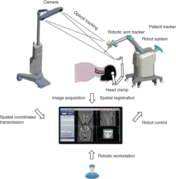
The working principles of the TianJi Robot system.
Computer‐Assisted Navigation Technique
A surgical assisted technique that combines modern computer, stereotactic, and medical imaging, to guide the surgeons for precise surgical planning and operation.
Orthopaedic Surgical Robotic Technique
A surgical assisted technique that combines computer‐assisted navigation and surgical robotics, to guide the surgeons for precise surgical planning and operation.
Patient Tracker
A tracker connected to the patient’s anatomy during surgery to reflect or emit infrared light to the optical tracking camera.
Robotic Arm
A mechanism having two or more degrees of freedom, a certain degree of autonomy, and that is capable of automatically performing a predetermined task according to human instructions.
Robotic Arm Tracker
A tracker connected to the robotic arm during surgery to reflect or emit infrared light to the optical tracking camera.
Camera
The main component of the optical tracking system, a mechanical device for spatial positioning and tracking.
Guider
A navigation surgical tool that is attached to the end of the robot arm for positioning the surgical trajectory and has a quick connection interface to the base.
Registration
A mechanical device for spatial coordinate mapping and calibration.
Robotic Workstation
The robotic workstation holds the navigation computer system, the surgical planning software, and the robot operation software.
Positioning
The process of moving the robotic arm and guider to the planned trajectory position.
Target Audience
All personnel who participate in orthopaedic robot‐assisted spinal surgery, which includes spine surgeons, nurses and engineers, are the target audience of this operative guideline. Manipulation of the surgical procedure and relative machine or mechanical devices should follow the standardized operative process recommended by the guideline. Proceed with precaution and consider the factors that could influence robotic navigation accuracy and endanger the patient’s safety.
Indications and Contraindications
Indications
Indications for treatment include: instability of the atlantoaxial joint caused by various pathogenesis with or without bulbomedullary compression; spinal anomalies atlas dysplasia (e.g. occipitalization of the atlas), axis dysplasia (e.g. os odontoid), basilar invagination, and Klippel Feil syndrome; spinal trauma, including odontoid fracture and transverse ligament injury; and autoimmune disease and tumors (rheumatoid arthritis and tumors compromising the atlantoaxial joint stability).
Contraindications
Contraindications include: systematic diseases, such as severe hemorrhagic disease, respiratory function failure, and other diseases that contraindicate general anesthesia or a major surgery; patient position requirement cannot be satisfied; patient cannot tolerate radiation exposure; tracker position cannot meet the needs of accurate navigation; and a qualified navigation image cannot be obtained.
Robot‐Assisted Procedures
Patient Preparation
After general anesthesia, patient positioning is the same as the requirements for traditional procedures: place the patient in a prone position and fix the head onto the operating table using the Mayfield frame. If Magerl’s procedure is performed and preoperative C1,2 dislocation exists, C1,2 reduction should be attempted by adjusting the position of the frame, which is monitored under fluoroscopy. If the C1,2 fusion is performed with autogenous iliac bone grafting, bone grafting is suggested to be performed prior to the C1,2 procedure.
During prepping and draping, an anchoring site for the patient tracker should be prepped and exposed. In open surgery, exposure is extended for anchoring the patient tracker. In percutaneous minimally invasive surgery, the patient tracker should be anchored at first and subsequently the stab wounds are created under robotic guidance.
Robotic Equipment Preparation
The TianJi Robot system consists of a robotic arm, an optical tracking system, a robotic workstation, and a navigation toolkit. The TianJi Robot system and the components around the robotic arm are shown in Figs. 2 and 3. All the relevant equipment is recommended to be arranged as follows in the operating room (Fig. 4).
Figure 2.
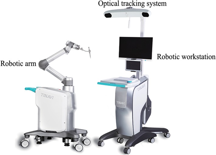
TianJi Robot system.
Figure 3.
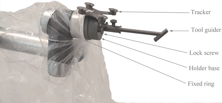
TianJi Robot navigation and positioning tools installation, including fixed ring, tracker, tool guider, lock screw, and holder base.
Figure 4.
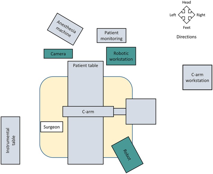
Schematic diagram of operation room. When performing robotic surgery, it is recommended that the operation room be arranged as shown.
Posterior Atlantoaxial Transarticular Screw Internal Fixation (Magerl Technique)
The patient tracker is commonly anchored onto the adjacent vertebral spinous process. The clamp connecting the patient tracker to the spinous process should be tightened and then the patient tracker is switched on (during open surgery: anchor the patient tracker onto the C3 or C4 spinous process; during percutaneous surgery: anchor the patient tracer onto the Mayfield frame). If posterior sub‐laminar wire fixation (Brooks technique) is performed at the same setting, the titanium cable is passed beneath the C1 and C2 lamina. Tighten the titanium cable, and the temporary clamp is used to fasten the titanium cable.
Adjust the position of the camera towards the operation space and the patient tracker.
Install the registration and place it into the operating area so that the registration is within the fluoroscopy field.
Image acquisition: Perform 3D image scanning and complete the registration and spatial registration.
Designing and planning: Plan bilateral Magerl screws’ parameters (diameter, length) in the robotic workstation. The screw entry point and the direction are designed based on the 3D images.
After the screw guider is installed, move the guider to the surgical field. The positioning accuracy will be displayed in the software interface in real time during the movement of the robot arm. Note: (i) If you find that the robot arm may touch the patient or surrounding obstacles, immediately press the emergency stop button; and (ii) the guider should be as close as possible to the operating area.
Sleeve installation: Place the sleeve into the screw guider. For percutaneous minimally invasive surgery, stab wounds can be made according to the position of the sleeve in contact with the skin. For open surgery, the sleeve is brought to the cortical bone surface after the bony surface is exposed.
Screw placement: The K‐wire was drilled into the vertebrae, and then the optimal position is verified by fluoroscopy. If it is a cannulated screw, it can be instrumented directly along the K‐wire; if it is a conventional screw, use the cannulated tap to prepare the trajectory first, and then insert the screw.
Remaining procedures: After the instrumentation is completed, verify the screw position by fluoroscopy. If the bone graft fusion is planned, complete corresponding operations.
C1 Lateral Mass Screw and C2 Pedicle Screw Internal Fixation (Harms Technique)
The patient tracker is commonly anchored onto the adjacent vertebral spinous process. The clamp connecting the patient tracker to the spinous process should be tightened and then the patient tracker is switched on (during open surgery: anchor the patient tracker onto the C3 or C4 spinous process; during percutaneous surgery: anchor the patient tracer onto the Mayfield frame).
Same as step (2) of Magerl technique.
Same as step (3) of Magerl technique.
Same as step (4) of Magerl technique.
Designing and planning: plan bilateral C1 lateral mass screw and C2 pedicle screw parameters (diameter, length) in the robotic workstation. The screw entry point and the direction are designed based on the 3D images.
Same as step (6) of Magerl technique.
Same as step (7) of Magerl technique.
Screw placement: The K‐wire is drilled into the vertebrae, and then the optimal position is verified by fluoroscopy. If it is a cannulated screw, it can be instrumented directly along the K‐wire; if it is a conventional screw, use the cannulated tap to prepare the trajectory first, and then insert the screw.
Remaining procedures: after the instrumentation is completed, verify the screw position by fluoroscopy. If the reduction is satisfactory, install the connecting rod and pre‐tighten the screw heads; if the repositioning is unsatisfactory, then further adjustment is needed for atlantoaxial alignment or the curvature of the connecting rod until the reduction is satisfactory. If the bone graft fusion is planned, complete the corresponding operation (Fig. 5).
Figure 5.
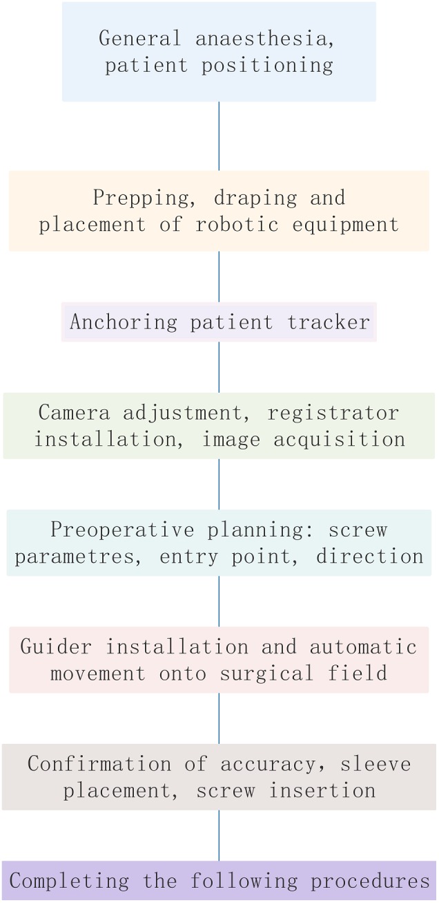
Workflow of robot‐assisted procedures.
Precautions
Robot‐assisted orthopaedic technology is a complex system based on advanced technologies such as image registration and fusion, robotics and automation technology, and precise equipment manufacturing. Its accuracy depends on these components of systems working properly; thus, it is affected by many factors. Common factors causing errors and strategies dealing with common errors are listed below.
Personnel Requirements
Doctors should have conventional surgical experience, relevant anatomical knowledge to determine whether the navigation system is accurate or not, and the ability to switch to conventional surgery when the robotic system fails to operate.
Environmental and Equipment Requirements
The operating room should have an appropriate area, with a good grounding system and power supply. The operating table should be radiolucent, avoiding metal artifacts that may affect the fluoroscopic process. The operating table base should not obstruct the intraoperative fluoroscopic machine obtaining intraoperative images. The operating environment should meet the normal working requirements according to the robot manual (including ambient temperature, humidity, air pressure, and voltage).
The preoperative navigation kit should be sterilized and placed on the operating table. The camera is placed on one side of the operating bed, above and facing towards the field, and cannot be blocked by the tray or the head frame. The C‐arm machine is moved from one side of the operating bed when it is used and is suggested to have a ground mark to guide the position properly. The main control trolley and the C‐arm should be far from the operating area to facilitate the technician’s operation.
Image Acquisition Requirements
The fluoroscopic images should demonstrate all the bony structures of key anatomical regions. The registration is clearly shown in the fluoroscopic field and the camera could simultaneously recognize and capture the spatial position information of the patient tracker and the robot arm tracker.
Tracker Placement Requirements
The tracker should be placed according to the operation and the patient’s condition. When placing an external tracker, it should be firmly anchoring on the free arm, and the free arm should be firmly anchored onto the Mayfield head frame to avoid errors.
Navigational Deviation: Image Drift
The spatial position of the anatomy at the surgical site is required to be relatively fixed after the images are acquired. Any factors causing the image deviations between the guided position and the real position are regarded as image drift. The doctor should have the ability to determine if the navigation image is drifting. When image drift is suspected, select obvious anatomical landmarks, such as apex of spinous process, facet joints or transverse roots for verification. If the positioning is accurate, continue the surgery; however, if it is uncorrectable drift, rescanning is necessary. Common reasons for image drift include the following items, which need to be noted.
Relative Displacement of the Anatomical Structures and the Patient Tracker
Due to the large degree of motion of the upper cervical vertebrae, if the surgeon is excessively pulling the soft tissue, it will cause a large relative displacement between the bony structures. Therefore, the intraoperative manipulation needs to be gentle, and the positioning accuracy should be noted during the manipulation.
Decompression or osteotomy will destroy the stability of the spine, resulting in relative displacement between the anatomical structures. If intraoperative conditions permit, the procedure of fixation is advised to be perform at first and followed by the remaining procedures to avoid image drift. If the accuracy is still uncertain, the doctor should select the anatomical landmark for verification.
If the patient’s position changes, it may cause the changing of the spatial position of the patient’s anatomical structures, and image acquisition and surgical planning should be re‐executed.
Patient Tracker Loosening
The patient tracker needs to be firmly anchored to the patient’s anatomy. If the intraoperative tool or the surgeon accidentally moves or touches the tracker, or the tracker is pulled by the skin during minimally invasive surgery, the position of the tracker would be changed. That will lead to a decrease in positioning accuracy or a failure in positioning. In this situation, image acquisition and surgical planning should be repeated.
Misalignment Caused by Lighting Problems
The robot system must maintain good reflection and reception of infrared light. If the angle or distance exceeds the receiving range, or other light interference, it may cause misalignment. The camera should be adjusted so that the surgical field is in the center of its detection range. Since the tracker reflects the light to the camera, strong direct light and blood staining on the refection ball of the tracker may interfere the refection and reception process of infrared light. Thus, strong direct light or blood staining on the tracker should be avoided.
Regular Maintenance of Robot Equipment
Data cable: Check whether the transmission data line interface is loosening or disconnected. If the data cable is aging, it needs to be replaced.
Robotic tools: Before the operation, the robot tool should be carefully checked for metal fatigue to prevent the tool from breaking during the operation.
System accuracy: Accuracy calibration should be performed periodically.
Others
The upper cervical vertebra has a high degree of movement, which requires a careful and experienced surgeon. If the robotic arm is found to be unable to reach the designated position due to the surrounding environment during the operation, the surgical path should be adjusted. If there is a sudden power failure of the robot system, the system should be restarted: If only the mechanical system of the mechanical arm is powered off, it is generally unnecessary to reacquire images and redo the surgical planning, but if the overall system of the robot is powered off, the image acquisition and surgical planning should be repeated.
List of Names of Consultant Specialists
Lin Cai, Xiang‐yang Cao, Huan‐sheng Fang, Chun‐zheng Gao, Ding‐jun Hao, Yong‐cheng Hu, Ming Li, Chun‐xia Li, Chun‐de Li, Kai‐nan Li, Yi Liao, Hao Liu, Bao‐ge Liu, Jun Liu, Shi‐dong Liu, Xin‐yu Liu, Ya‐jun Liu, Xin‐long Ma, Cai‐liang Shen, Hong‐xing Shen, Yue‐ming Song, Tian‐sheng Sun, Wei Tian, Yue Wang, Ya‐yi Xia, Jian‐zhong Xu, Hui‐lin Yang, Xue‐jun Yang, Guo‐yong Yin, Shu‐dong Zhang, Wei‐guo Zhang, Yu Zhao, Yue Zhu.
Acknowledgments
This guideline was created and revised by multiple consultant specialists in several associations, including the Technical Committee on Medical Robot Engineering of the Chinese Society of Biomedical Engineering, the Medical Robotics Branch of the Chinese Medical Doctor Association, and the Chinese Orthopaedic Association of the Chinese Medical Association. We are grateful for their support and contributions.
Grant Sources: This work was supported by the National Key R&D Program of China (2016YFC0105800), the National Natural Science Foundation of China (CN) (U1713221); Beijing Natural Science Foundation (Z170001), and Beijing Municipal Science and Technology Program (CN) (Z171100000417019).
References
- 1. Li L, Yu X, Wang P, Chen L. Analysis of the treatment of 576 patients with congenital craniovertebral junction malformations. J Clin Neurosci, 2012, 19: 49–56. [DOI] [PubMed] [Google Scholar]
- 2. Goel A, Bhatjiwale M, Desai K. Basilar invagination: a study based on 190 surgically treated patients. J Neurosurg, 1998, 88: 962–968. [DOI] [PubMed] [Google Scholar]
- 3. Gallie WE. Skeletal traction in the treatment of fractures and dislocations of the cervical spine. Ann Surg, 1937, 106: 770–776. [DOI] [PMC free article] [PubMed] [Google Scholar]
- 4. Brooks AL, Jenkins EB. Atlanto–axial arthrodesis by the wedge compression method. J Bone Joint Surg Am, 1978, 60: 279–284. [PubMed] [Google Scholar]
- 5. Dickman CA, Sonntag VK, Papadopoulos SM, Hadley MN. The interspinous method of posterior atlantoaxial arthrodesis. J Neurosurg, 1991, 74: 190–198. [DOI] [PubMed] [Google Scholar]
- 6. Huang DG, Hao DJ, He BR, et al Posterior atlantoaxial fixation: a review of all techniques. Spine J, 2015, 15: 2271–2281. [DOI] [PubMed] [Google Scholar]
- 7. Mummaneni PV, Haid RW. Atlantoaxial fixation: overview of all techniques. Neurol India, 2005, 53: 408–415. [DOI] [PubMed] [Google Scholar]
- 8. Finn MA, Apfelbaum RI. Atlantoaxial transarticular screw fixation: update on technique and outcomes in 269 patients. Neurosurgery, 2010, 66(3 Suppl): 184–192. [DOI] [PubMed] [Google Scholar]
- 9. Grob D, Magerl F. Surgical stabilization of C1 and C2 fractures. Orthopade, 1987, 16: 46–54. [PubMed] [Google Scholar]
- 10. Harms J, Melcher RP. Posterior C1‐C2 fusion with polyaxial screw and rod fixation. Spine (Phila Pa 1976), 2001, 26: 2467–2471. [DOI] [PubMed] [Google Scholar]
- 11. Sim HB, Lee JW, Park JT, Mindea SA, Lim J, Park J. Biomechanical evaluations of various c1‐c2 posterior fixation techniques. Spine (Phila Pa 1976), 2011, 36: E401–E407. [DOI] [PubMed] [Google Scholar]
- 12. Rayner CF, Dewar A, Moxon ER, Virji M, Wilson R. The effect of variations in the expression of pili on the interaction of Neisseria meningitidis with human nasopharyngeal epithelium. J Infect Dis, 1995, 171: 113–121. [DOI] [PubMed] [Google Scholar]
- 13. Terterov S, Taghva A, Khalessi AA, Hsieh PC. Symptomatic vertebral artery compression by the rod of a C1‐C2 posterior fusion construct: case report and review of the literature. Spine (Phila Pa 1976), 2011, 36: E678–E681. [DOI] [PubMed] [Google Scholar]
- 14. Paramore CG, Dickman CA, Sonntag VK. The anatomical suitability of the C1‐2 complex for transarticular screw fixation. J Neurosurg, 1996, 85: 221–224. [DOI] [PubMed] [Google Scholar]
- 15. Igarashi T, Kikuchi S, Sato K, Kayama S, Otani K. Anatomic study of the axis for surgical planning of transarticular screw fixation. Clin Orthop Relat Res, 2003, 408: 162–166. [DOI] [PubMed] [Google Scholar]
- 16. Uchino A, Saito N, Watadani T, et al Vertebral artery variations at the C1‐2 level diagnosed by magnetic resonance angiography. Neuroradiology, 2012, 54: 19–23. [DOI] [PubMed] [Google Scholar]
- 17. Hong JT, Lee SW, Son BC, et al Analysis of anatomical variations of bone and vascular structures around the posterior atlantal arch using three‐dimensional computed tomography angiography. J Neurosurg Spine, 2008, 8: 230–236. [DOI] [PubMed] [Google Scholar]
- 18. Young JP, Young PH, Ackermann MJ, Anderson PA, Riew KD. The ponticulus posticus: implications for screw insertion into the first cervical lateral mass. J Bone Joint Surg Am, 2005, 87: 2495–2498. [DOI] [PubMed] [Google Scholar]
- 19. Lall R, Patel NJ, Resnick DK. A review of complications associated with craniocervical fusion surgery. Neurosurgery, 2010, 67: 1396–1402 discussion 1402–1403. [DOI] [PubMed] [Google Scholar]
- 20. Weng C, Tian W, Li ZY, et al Surgical management of symptomatic os odontoideum with posterior screw fixation performed using the magerl and harms techniques with intraoperative 3‐dimensional fluoroscopy‐based navigation. Spine (Phila Pa 1976), 2012, 37: 1839–1846. [DOI] [PubMed] [Google Scholar]
- 21. Yang Y, Wang F, Han S, et al Isocentric C‐arm three‐dimensional navigation versus conventional C‐arm assisted C1‐C2 transarticular screw fixation for atlantoaxial instability. Arch Orthop Trauma Surg, 2015, 135: 1083–1092. [DOI] [PubMed] [Google Scholar]
- 22. Yang YL, Zhou DS, He JL. Comparison of isocentric C‐arm 3‐dimensional navigation and conventional fluoroscopy for C1 lateral mass and C2 pedicle screw placement for atlantoaxial instability. J Spinal Disord Tech, 2013, 26: 127–134. [DOI] [PubMed] [Google Scholar]
- 23. Fan Y, Du J, Zhang J, et al Comparison of accuracy of pedicle screw insertion among 4 guided technologies in spine surgery. Med Sci Monit, 2017, 23: 5960–5968. [DOI] [PMC free article] [PubMed] [Google Scholar]
- 24. Liu H, Chen W, Wang Z, Lin J, Meng B, Yang H. Comparison of the accuracy between robot‐assisted and conventional freehand pedicle screw placement: a systematic review and meta‐analysis. Int J Comput Assist Radiol Surg, 2016, 11: 2273–2281. [DOI] [PubMed] [Google Scholar]
- 25. Roser F, Tatagiba M, Maier G. Spinal robotics: current applications and future perspectives. Neurosurgery, 2013, 72(1 Suppl): 12–18. [DOI] [PubMed] [Google Scholar]
- 26. Bertelsen A, Melo J, Sánchez E, Borro D. A review of surgical robots for spinal interventions. Int J Med Robot, 2013, 9: 407–422. [DOI] [PubMed] [Google Scholar]
- 27. Tian W. Robot‐assisted posterior C1‐2 transarticular screw fixation for atlantoaxial instability: a case report. Spine (Phila Pa 1976), 2016, 41(19 Suppl): B2–B5. [DOI] [PubMed] [Google Scholar]


