Abstract
Objective To analyze the stability of humerus supracondylar fracture fixation with Kirschner wires comparing intramedullary and lateral (Fi), and two parallel lateral wires (FL) fixation in experimental models, to define which configuration presents greater stability.
Methods A total of 72 synthetic humeri were cross-sectioned to simulate the fracture. These bones were divided into two equal groups and the fractures were fixed with parallel Kirschner wires (FL) and with a lateral and intramedullary (Fi) wire. Then, the test specimens were subjected to stress load tests on a universal test machine, measured in Newtons (N). Each group was subdivided into varus load, valgus, extension, flexion, external rotation and internal rotation. An analysis of the data was performed comparing the subgroups of the FL group with their respective subgroups of the Fi group through the two-tailed t test.
Results The two-tailed t test showed that in 4 of the 6 evaluated conditions there was no significant statistical difference between the groups ( p > 0.05). We have found a significant difference between the group with extension load with a mean of 19 N (FL group) and of 28.7 N (Fi group) ( p = 0.004), and also between the groups with flexural load with the mean of the forces recorded in the FL group of 17.1 N and of 22.9 N in the Fi group ( p = 0.01).
Conclusion Fixation with one intramedullary wire and one lateral wire, considering loads in extension and flexion, presents greater stability when compared to a fixation with two lateral wires, suggesting similar clinical results.
Keywords: biomechanical phenomena, epiphyses/injuries, fracture fixation, humeral fractures
Introduction
Supracondylar fracture is more common in the 4- to 7-year-old age group, 1 corresponding to two-thirds of children hospitalized for elbow trauma and to 30% of the fractures in this population. 2 Due to the particular anatomy of the elbow and to the ossification order in the growth nuclei, the supracondylar fracture virtually always behaves in extension patterns, with posterior medial, posterior lateral and flexion displacements. The displacement degree is defined by the direction of the deforming force, by the position of the limb during the trauma, and by the magnitude of this force. 3 4
Gartland classified this fracture in three types according to the displacement degree; it is agreed that grade 1 fractures require conservative treatment. 5 Some papers describe conservative techniques, that is, reduction and immobilization, in grade 2 and 3 fractures. 6 However, many authors describe reduction and percutaneous fixation as the gold standard for displaced fractures. 7 8 As such, there is no consensus as to the best positioning of Kirschner wires in the stabilization of this fracture. 9 Fixation with a cross-wired configuration provides better stability, but there is a risk of iatrogenic injury of the ulnar nerve. The configuration with two lateral wires showed lower stability of the crossed wires and lower incidence of ulnar nerve lesions; in addition, it is technically more challenging, since the space for wire placement both in divergent and parallel directions is small. However, both configurations have similar clinical results. 10 11 12 13
In 1991, Bertol et al 14 published the technique of supracondylar fractures fixation with posterior medial deviation using an intramedullary Kirschner wire inserted just lateral to the olecranon and another one lateral at the epicondyle entry, in a presumably easier technique, since it optimizes the lateral spine space.
Numerous biomechanical studies compare different positional configurations of Kirchner wires in the stabilization of supracondylar humerus fracture, 13 15 16 but there are no reports analyzing the configuration with an intramedullary and a lateral wire. The present study aims to compare fixation techniques using an intramedullary wire or two parallel lateral wires.
Materials and Methods
The test specimens of the present study were 72 synthetic humeri (model 3022B – left humerus with medullary canal and spongy material) (Nacional Ossos, Jaú, SP, Brazil), which were equally cross-sectioned, parallel to the articular surface in the coronal plane, with a distal guided saw; the section passed into the olecranon fossa at 3 centimeters from the distal humeral edge, simulating a supracondylar fracture ( Fig. 1 ). The cross-section was selected because 80% of the supracondylar fractures have a transverse pattern in lateral radiographs 17 ; moreover, the fracture obliquity causes instability. 18
Fig. 1.

Test specimens: cross-section of a synthetic humerus at its distal portion, through the olecranon fossa at 3 centimeters from the distal edge of the bone, simulating a supracondylar fracture.
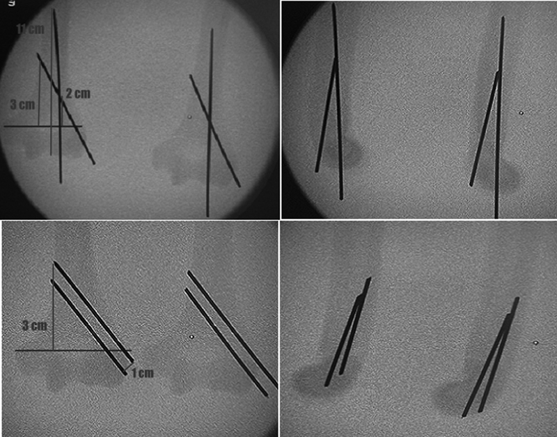
The sectioned synthetic humeri were divided into two groups according to fixation: a group fixed with two lateral wires (FL) and a group with fixed with an intramedullary wire and a lateral wire (Fi). All of the models were submitted to the anatomical reduction and fixation with 2.0 mm Kirschner wires. Each group had a standard fixation model to assure that the fixations were identical. In the FL group, the fixation was performed with 2 2.0 mm Kirschner wires entering laterally at the epicondyle, with the most distal wire at the lower edge of the lateral epicondyle and the proximal wire 1 cm above the former, parallel to the axis of the humeral shaft, fixed on the opposite cortical layer, 3 cm above the fracture line.
In the Fi group, the fixation was also performed with 2 2.0 mm Kirschner wires, with the 1 st wire entering 2 mm lateral to the lateral border of the trochlea, at the trochlear groove, thus becoming intramedullary and introduced up to the transition between the middle third and the distal third of the humerus, 11 cm from the distal humeral end, and the 2 nd wire inserted in the center of the lateral epicondyle at a 30° angle to the humeral axis, crossing the 1 st wire at 2 cm from the fracture line and fixed in the opposite cortical layer at 3 cm from the fracture line.
Fixations were aided by a perforator and fluoroscopy. All of the specimens were compared to their respective standardized models by fluoroscopy, complying with the previously mentioned fixation criteria, and assuring the similarity between them ( Fig. 2 ).
Fig. 2.
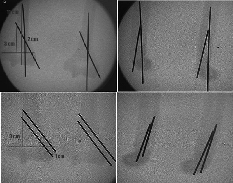
Test specimens compared with their respective standardized models at fluoroscopy, complying with the fixation criteria and ensuring the similarity between them.
Specimens that did not comply with the fixation criteria were excluded. After the fixation, the humeri from both groups were sent to the Engineering Laboratory, where, together with a collaborating engineer, each group was divided into subgroups according to the performed load tests: subgroup 1, varus load; subgroup 2, valgus load; subgroup 3, load in extension; subgroup 4, load in flexion; subgroup 5, load in internal rotation; and subgroup 6, load in external rotation.
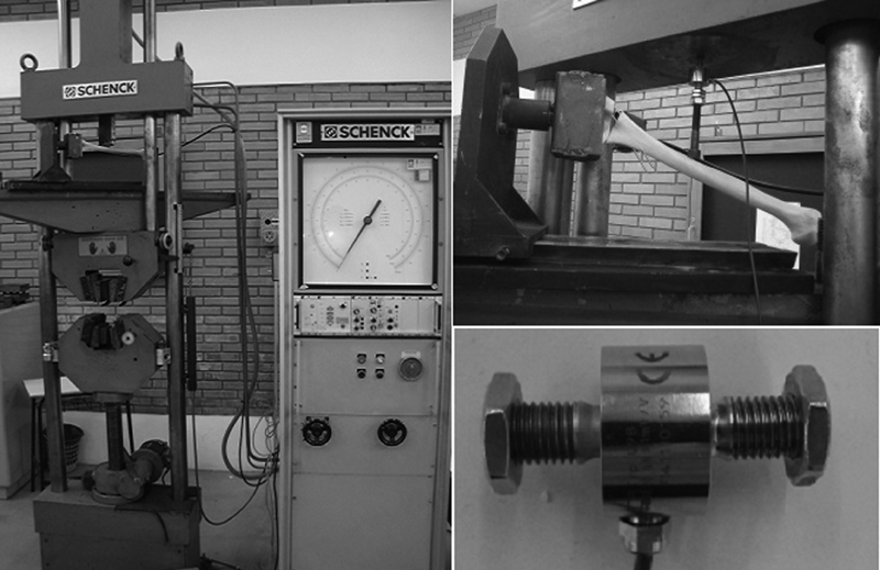
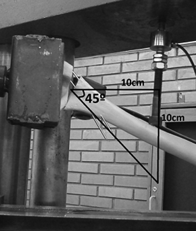
Load tests were performed on a universal tensile testing machine, model UPM 200 (3022B, left humerus with medullary canal and spongy material, Nacional Ossos, Jaú, SP, Brazil), and an HBM U9B (3022B, left humerus with medullary canal and spongy material, Nacional Ossos, Jaú, SP, Brazil) load cell (20KN = 1mV/V). The test measures the load generated in Newtons (N) during the continuous displacement promoted by the traction test machine at a speed of 1 mm/s, with a maximum established displacement of 10 cm, which promotes an angulation of up to 45° in the specimen with rotation fulcrum at the fracture line ( Fig. 3 ).
Fig. 3.
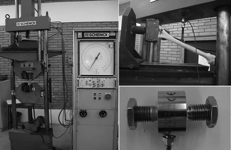
Universal tensile testing machine model UPM 200 and an HBM U9B load cell (20 KN = 1 mV/V)
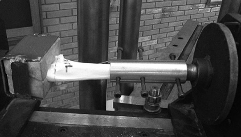
A support for the anatomical coupling of the distal humerus was developed, allowing the application and measurement of loads in bone models at a point 10 cm proximal to the fracture line up to a 45° of angulation and/or material failure ( Fig. 4 ). A mechanism to create rotational forces from the load established by the tensile testing machine was also developed ( Fig. 5 ). Rotational loads were applied until the breakage of the bone models.
Fig. 4.
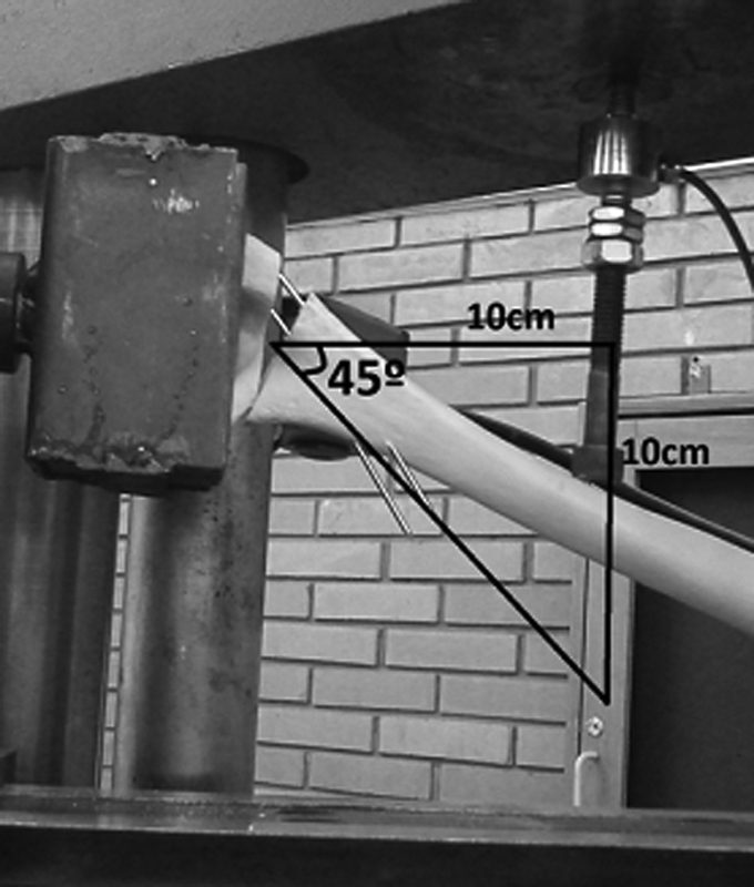
Applied and measured loads on the specimens, at a point 10 cm proximal to the fracture line, until reaching a 45° angle and/or material failure.
Fig. 5.
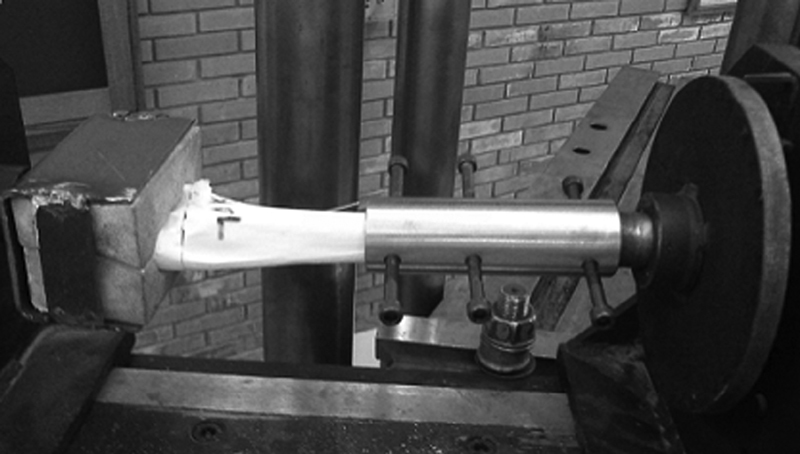
Mechanism for the application of rotational loads.
The data generated by the load cell in each bone model show that, during displacement, the force in N initially increases until it reaches a plateau (which is related to the higher recorded forces); next, the applied force decreases, which is related to the bone model breakage and/or to a 45° displacement. In this way, the force in N when reaching this plateau was defined as the variable to be analyzed, that is, the maximum force recorded during the displacement, at the end of the linear region of the graph.
The sample size was calculated in the PEPI (Programs for Epidemiologists) software, version 4.0, and based on the study by Bloom et al . 19 For a significance level of 5%, 90% power, and an estimated standard deviation [SD] of 3.5 with a mean difference of 8N, a minimum total of 6 parts per subgroup was obtained, totaling 36 per group.
The data analysis was performed with Microsoft Office Excel 2010 software (Microsoft Corporation, Redmond, WA, USA), comparing FL subgroups to their respective Fi subgroups through two-tailed t tests. The present study does not have conflicts of interests.
Results
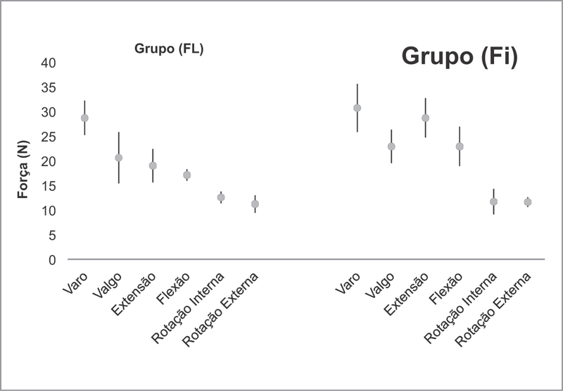
Loading tests results to compare the stability of the two wire configurations are represented in N in Table 1 . The two-tailed t test showed that there was no significant statistical difference in 4 of the 6 loads applied ( p < 0.05 ) ( Table 1 ).
Table 1. Mechanical load force and direction data.
| Group (FL) | Group (Fi) | Two-tailed t test | |
|---|---|---|---|
| Varus (N) | 28.7 ± 3.5 | 30.7 ± 4.9 | p = 0.230 |
| Valgus (N) | 20.6 ± 5.2 | 22.9 ± 3.4 | p = 0.240 |
| Extension (N) | 19.0 ± 3.4 | 28.7 ± 4.0 | p = 0.004 |
| Flexion (N) | 17.1 ± 1.2 | 22.9 ± 4.0 | p = 0.015 |
| Internal Rotation (N) | 12.55 ± 1.2 | 11.7 ± 2.6 | p = 0.256 |
| External Rotation (N) | 11.2 ± 1.8 | 11.6 ± 1.0 | p = 0.292 |
Abbreviations: Fi, fixation with intramedullary and lateral wires; FL, fixation with two lateral wires; N, Newtons.
In the bone models submitted to the varus load, the mean of the highest recorded forces during displacement in FL group was of 28.7 N, with a SD of 3.5 N. In the Fi group, the mean force was 30.7 N, with a SD of 4.9 N. Thus, the two-tailed t test did not reveal a statistically significant difference between these groups ( p = 0.23 ) ( Fig. 6 ).
Fig. 6.
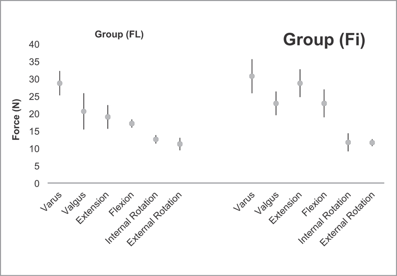
Graphic representation of test results of loads in varus, valgus, extension and flexion and internal and external rotation.
In the models submitted to valgus load, the mean of the highest recorded forces in the FL group was of 20.6 N, with a SD of 5.2 N. In the Fi group, the mean value was of 22.9 N, with a SD of 3.4 N. As with the varus load, the two-tailed t test did not reveal a statistically significant difference between the groups ( p = 0.24 ) ( Fig. 6 ).
In addition, there was no statistically significant difference between the groups at the load tests in internal and external rotation ( p = 0.25 and p = 0.24 , respectively) ( Fig. 6 ).
There was a statistically significant difference between the 2 groups in the extension load tests ( p = 0.004 ), with a mean of the highest recorded forces in the FL group of 19.0 N and a SD of 3.4 N, whereas the Fi group presented a value of 28.7 Newtons and a SD of 4.0 N ( Fig. 6 ). Thus, during the constant displacement established by the test machine, a greater force was generated and recorded by the load cell in the Fi group compared with the FL group. As such, we can also suggest that the configuration with an intramedullary wire and a lateral wire provides greater stability in extension loads when compared with the configuration with two parallel lateral wires.
Models submitted to the flexion load also showed a significant statistical difference between the groups ( p = 0.01 ), with the mean of the highest recorded forces in the FL group of 17.1 N and a SD of 1.2 N, and a mean value of 22.9 N and a SD of 4 N in the Fi group ( Fig. 6 ).
Discussion
The main goals of the treatment of displaced supracondylar fractures are anatomic reduction and a secure fixation with no angular deformities. This is usually achieved with closed reduction and percutaneous fixation. 20 21 22 Fixation requires full attention to the clinical and radiological examination of the contralateral elbow, in addition to true orthogonal projections at fluoroscopy and the consideration of well-described radiographic parameters for total correction of the deformity. 23 Defective consolidations are also related to inadequate fixations and technical errors during the procedure. 19
Several biomechanical studies have demonstrated that the cross-wire fixation has a greater rotational stability than the lateral wiring fixations, 15 but with a higher risk of iatrogenic injury of the ulnar nerve. 12 Bloom et al 16 reported that three lateral divergent pins provides the same resistance as two crossed wires, which are more resistant than two lateral wires, but, in most cases, there is not enough space for lateral pinning. 19 In a prospective randomized clinical trial comparing lateral and crossed fixation techniques for the treatment of type III humeral supracondylar fractures, Kocher et al 11 did not find a significant difference between both groups regarding radiographic and clinical outcome. In another prospective randomized study, Blanco et al 24 found no significant radiological differences between crossed and lateral wiring fixation.
Our study shows that the technique with intramedullary wire presents a greater resistance under flexion and extension loads than the technique with lateral wires; at other loads, the results are similar. In the former technique, the first step after achieving a suitable reduction is the introduction of the intramedullary wire, 14 which blocks the forces in axial direction, mainly flexion and extension, safely allowing the correction of the remaining rotational deformities, that is, this technique tolerates a rotational adjustment after the precise reduction in the axial direction, which is not possible with lateral wiring. As such, the intramedullary wire fixation facilitates anatomical reduction, which maximizes the stability of all fixation configurations. 19 In addition, intramedullary wire fixation maintains a greater lateral space for wire placement.
Since the clinical results of the two crossed wires technique are similar to those obtained with two lateral wires, 1 24 25 26 we can assume that, according to the present mechanical study, the clinical results of the fixation with an intramedullary wire are equivalent to those provided by these techniques; however, a randomized clinical trial is required to confirm this assumption.
Some limitations of the present study should be recognized. Although the use of synthetic models for mechanical analysis of fracture reduction techniques is common in the literature, these investigations do not consider the variability in fracture patterns nor the anatomy with the surrounding periosteum that may contribute to fragment stability. 15 27 Furthermore, the physiological loads acting on the elbow are certainly more complex than the single axis of the load test directions used in the present study. In addition, the pins were placed in an ideal situation, without considering the difficulty of intraoperative insertion, which cannot be simulated. The design of the present study does not allow direct comparisons of the applied loads in models with organic bones, allowing only the comparison between the fixation techniques for these fractures.
Conclusion
In the present study, the intramedullary wire fixation provides a greater stability under flexion and extension loads when compared with the lateral wiring fixation, with similar results under other applied loads, suggesting acceptable clinical results, as already proven by Bertol et al. 14 As such, it is an excellent option for the configuration of Kirschner wires when treating these fractures.
Conflitos de Interesses Os autores declaram não haver conflitos de interesses.
Trabalho realizado no Hospital São Vicente de Paulo, Passo Fundo, RS, Brasil.
Worked performed at the Hospital São Vicente de Paulo, Passo Fundo, RS, Brazil.
Referências
- 1.Cheng J C, Shen W Y. Limb fracture pattern in different pediatric age groups: a study of 3,350 children. J Orthop Trauma. 1993;7(01):15–22. doi: 10.1097/00005131-199302000-00004. [DOI] [PubMed] [Google Scholar]
- 2.Kasser J R, Beaty J H. Philadelphia: Lippincott Williams and Wilkins; 2006. Supracondylar fractures of the distal humerus; pp. 543–89. [Google Scholar]
- 3.Omid R, Choi P D, Skaggs D L. Supracondylar humeral fractures in children. J Bone Joint Surg Am. 2008;90(05):1121–1132. doi: 10.2106/JBJS.G.01354. [DOI] [PubMed] [Google Scholar]
- 4.Mahan S T, May C D, Kocher M S. Operative management of displaced flexion supracondylar humerus fractures in children. J Pediatr Orthop. 2007;27(05):551–556. doi: 10.1097/01.bpb.0000279032.04892.6c. [DOI] [PubMed] [Google Scholar]
- 5.Barton K L, Kaminsky C K, Green D W, Shean C J, Kautz S M, Skaggs D L. Reliability of a modified Gartland classification of supracondylar humerus fractures. J Pediatr Orthop. 2001;21(01):27–30. doi: 10.1097/00004694-200101000-00007. [DOI] [PubMed] [Google Scholar]
- 6.Izadpanah M. [Closed treatment of supracondylar fractures of the humerus: a modification of Blounts technique (author's transl)] Arch Orthop Unfallchir. 1973;77(04):348–358. doi: 10.1007/BF00418920. [DOI] [PubMed] [Google Scholar]
- 7.Wilkins K, Beaty J. Philadelphia: Lippincott-Raven; 1996. Fractures in children. 4th ed. [Google Scholar]
- 8.Flynn J C, Zink W P. Baltimore: Willians &Wilkins; 1993. Fractures and dislocations of the elbow; pp. 133–64. [Google Scholar]
- 9.Kasser J R, Beaty J H. Philadelphia: Lippincott Williams and Wilkins; 2004. Supracondylar fractures of the distal humerus; pp. 594–95. [Google Scholar]
- 10.Topping R E, Blanco J S, Davis T J. Clinical evaluation of crossed-pin versus lateral-pin fixation in displaced supracondylar humerus fractures. J Pediatr Orthop. 1995;15(04):435–439. doi: 10.1097/01241398-199507000-00004. [DOI] [PubMed] [Google Scholar]
- 11.Kocher M S, Kasser J R, Waters P M, Bae D, Snyder B D, Hresko M T et al. Lateral entry compared with medial and lateral entry pin fixation for completely displaced supracondylar humeral fractures in children. A randomized clinical trial. J Bone Joint Surg Am. 2007;89(04):706–712. doi: 10.2106/JBJS.F.00379. [DOI] [PubMed] [Google Scholar]
- 12.Rasool M N. Ulnar nerve injury after K-wire fixation of supracondylar humerus fractures in children. J Pediatr Orthop. 1998;18(05):686–690. doi: 10.1097/00004694-199809000-00027. [DOI] [PubMed] [Google Scholar]
- 13.Brauer C A, Lee B M, Bae D S, Waters P M, Kocher M S. A systematic review of medial and lateral entry pinning versus lateral entry pinning for supracondylar fractures of the humerus. J Pediatr Orthop. 2007;27(02):181–186. doi: 10.1097/bpo.0b013e3180316cf1. [DOI] [PubMed] [Google Scholar]
- 14.Bertol P, Monteggia G M, Paula M D. Fixação percutânea das fraturassupracondilianas do úmero na criança. Rev Bras Ortop. 1991;26(03):48–51. [Google Scholar]
- 15.Larson L, Firoozbakhsh K, Passarelli R, Bosch P. Biomechanical analysis of pinning techniques for pediatric supracondylar humerus fractures. J Pediatr Orthop. 2006;26(05):573–578. doi: 10.1097/01.bpo.0000230336.26652.1c. [DOI] [PubMed] [Google Scholar]
- 16.Bloom T, Robertson C, Mahar A, Pring M, Newton P O.Comparison of supracondylar humerus fracture pinning when the fracture is not anatomically reducedIn: The Annual Meeting of the Pediatric Orthopaedic Society of North America, Hollywood, FL, 2007 May 23-26
- 17.Nand S. Management of supracondilar fractures in children. Int Surg. 1972;177:203–209. [PubMed] [Google Scholar]
- 18.Bahk M S, Srikumaran U, Ain M C, Erkula G, Leet A I, Sargent M C et al. Patterns of pediatric supracondylar humerus fractures. J Pediatr Orthop. 2008;28(05):493–499. doi: 10.1097/BPO.0b013e31817bb860. [DOI] [PubMed] [Google Scholar]
- 19.Bloom T, Robertson C, Mahar A T, Newton P. Biomechanical analysis of supracondylar humerus fracture pinning for slightly malreduced fractures. J Pediatr Orthop. 2008;28(07):766–772. doi: 10.1097/BPO.0b013e318186bdcd. [DOI] [PubMed] [Google Scholar]
- 20.Kurer M H, Regan M W. Completely displaced supracondylar fracture of the humerus in children. A review of 1708 comparable cases. Clin Orthop Relat Res. 1990;(256):205–214. [PubMed] [Google Scholar]
- 21.Royce R O, Dutkowsky J P, Kasser J R, Rand F R. Neurologic complications after K-wire fixation of supracondylar humerus fractures in children. J Pediatr Orthop. 1991;11(02):191–194. doi: 10.1097/01241398-199103000-00010. [DOI] [PubMed] [Google Scholar]
- 22.Ito N, Eto M, Maeda K, Rabbi M E, Iwasaki K. Ultrasonographic measurement of humeral torsion. J Shoulder Elbow Surg. 1995;4(03):157–161. doi: 10.1016/s1058-2746(05)80045-x. [DOI] [PubMed] [Google Scholar]
- 23.Pring M, Rang M, Wenger D. Philadelphia, PA: Lippincott Williams & Wilkins; 2005. Elbow-distal humerus; pp. 95–118. [Google Scholar]
- 24.Blanco J S, Gaston G, Cates T, Busch M T, Schmitz M L, Schrader Tet al. Lateral pin versus crossed pin fixation in type 3 supracondylar humerus fractures: a randomized prospective studyIn: The Annual Meeting of the Pediatric Orthopaedic Society of North America, Hollywood, FL, 2007 May 23-26.
- 25.Foead A, Penafort R, Saw A, Sengupta S. Comparison of two methods of percutaneous pin fixation in displaced supracondylar fractures of the humerus in children. J Orthop Surg (Hong Kong) 2004;12(01):76–82. doi: 10.1177/230949900401200114. [DOI] [PubMed] [Google Scholar]
- 26.Gordon J E, Patton C M, Luhmann S J, Bassett G S, Schoenecker P L. Fracture stability after pinning of displaced supracondylar distal humerus fractures in children. J Pediatr Orthop. 2001;21(03):313–318. [PubMed] [Google Scholar]
- 27.Schwartz A, Oka R, Odell T, Mahar A. Biomechanical comparison of two different periarticular plating systems for stabilization of complex distal humerus fractures. Clin Biomech (Bristol, Avon) 2006;21(09):950–955. doi: 10.1016/j.clinbiomech.2006.04.018. [DOI] [PubMed] [Google Scholar]


