Abstract
A major challenge in theranostics is the synthesis of hybrid structures that exhibit multiple functions that cannot be achieved in a single-phase material. The combination of inorganic, polymeric and bio-organic components holds great promise as novel hybrid biomaterials, but a stable assembly of such different components is not easy to attain. Additionally, the development of magnetothermal neuromodulation and magnetic hyperthermia therapies requires magnetic nanoparticles (MNPs) with high heating power. However, MNPs tend to agglomerate in-vivo applications degrading their heating potential due to dipolar interaction effects. Ferromagnetic nanoparticles (F-MNPs), with own permanent magnetic dipole, present larger magnetic response than superparamagnetic nanoparticles (SP-MNPs) but they also agglomerate much easier. Herein, we present an original and versatile approach to engineer inorganic-polymeric microdisks loaded with Fe3O4 F-MNPs, fluorophores and biomolecules. By developing a mushroom-shaped sacrificial template and carefully controlling the assembly conditions we have been able to tailor multifunctional microdisks containing a monolayer of F-MNPs with tunable densities and devoid of undesirable dipolar interactions. Local heat generated in microdisks attached to the cell membrane has been found to be proportional to the surface density of F-MNPs. These magnetic hybrid microdisks have proven to be firmly attached to the cell membrane and are endocytosis resistant, which make them stable sub-cellular implants for efficient magnetothermal actuation.
Keywords: photolithography, microdisks, layer-by-layer, ferromagnetic-nanoparticles, dipolar-interactions, endocytosis-resistance, fluorescence-thermometry
Graphical Abstract
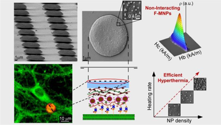
An original and versatile approach is developed to engineer multilayered inorganic-polymeric microdisks loaded with ferromagnetic nanoparticles, fluorophores and biomolecules in uniform arrangement, emerging as novel subcellular-sized implants that allow a precise control of the heating efficiency in the biological target.
INTRODUCTION
Magnetic nanoparticles (MNPs), specifically iron oxide magnetic nanoparticles, have emerged as powerful cell actuators via local thermal effects, as in deep brain magnetothermal neuromodulation 1,2,3 or force application.4,5,6 Both, the magnetothermal actuation, as well as the forces achievable for mechanical stimulation, are maximized by using ferromagnetic nanoparticles (F-MNPs) with high permanent magnetic moments. However, F-MNPs with high magnetic moments are prone to interact with each other in biological samples giving rise to large clusters. Prior studies have shown that magnetic heating,7 contrast signal,8 and magnetic trapping9 are significantly reduced when MNPs are located within tissues and the reduced magnetic response has been correlated with increased MNP clustering.10,11 Improving the heat delivery for magnetothermal cell actuator requires therefor the development of systems which prevent MNP aggregation while keeping areas of high MNP density.
In addition, when deploying a synthetic cell actuator, it is of utmost importance that the actuator remains in place, e.g. on the cell surface. Endocytic or phagocytic uptake would render the actuator functionless and likely stimulate an immune response.12 It has been shown that particle shape and geometry affect endocytosis rate greatly.13 It has been observed that spherical, rod-like and polyhedral micro- and nanostructures are typically internalized within minutes.14–16 In contrast, flat disk-like microstructures have shown much greater endocytosis resistance17,18 and micro-elliptical disks have displayed better targeting efficiency for accumulation in tissues than spheres of different diameters (from 100 nm to 10 μm).19 Hence, flat disk-like structures are ideal candidates to maximize the residence time on the desired target and, consequently, optimize the efficacy of specific biomedical applications, while minimizing toxicity resulting from mistargeted material. An important benefit of disks assembled from several nanoscale components is the possibility to integrate various functional cargos, such as magnetic nanoparticles, fluorescent dyes and biomolecules. Therefore, such multifunctional microdisks will allow for simultaneous and synergistic diagnostics, therapeutics and monitoring of the response to treatments if they fulfill the following requirements: mechanical stability to remain flat and united, nanometer-thin to reach spaces between cells, void of sharp protrusions to minimize damage, defined surface chemistry, and a porous, flexible cargo loading region.
Thin polymeric multilayer materials, such as polydiallyl-dimethylammonium chloride (PDAC), polysodium 4-styrenesulfonate (PSS) and poly(allylamine hydrochloride) (PAH), provide ease of loading with drugs and nanoparticles.20,21 But their lack of rigidity and tendency to fold or break22–24 limits their applications. One solution would be to merge an inorganic thin film (nontoxic and fracture resistant) with a polymeric multilayer, creating a bio-hybrid with the desired properties: physical integrity, multifunctionality and biocompatibility. But precisely, engineer flat inorganic-polymeric microstructures is a very challenging task.
In this work, we present how the fabrication of a mushroom-shaped template allows for the production of inorganic-organic multifunctional microdisks that greatly meet all the above-mentioned requirements. The novel approach introduced herein allows the fabrication of inorganic-polymeric microdisks (several tens of nanometers thick: 50–200 nm, and a few microns in diameter: 5–10 μm) loaded with Fe3O4 F-MNPs, fluorophores and biomolecules. The process offers fine control over the physical distribution of the F-MNPs and is compatible with a wide range of NPs, fluorophores and proteins. We also demonstrate that microdisks can be successfully targeted to the surface of various cells and form stable and long-term bonds with the cell-membrane, providing unique opportunities for the development of theranostics and remote control of cell-signaling.
RESULTS AND DISCUSSION
Fabrication of mushroom-shaped template: Photolitography in bilayer process.
The production of the bio-hybrid microdisks begins with the preparation of mushroom-shaped patterns by photolithography. Then, the inorganic, polymeric and bio-organic components are deposited on top of the template and the resulting assembly is released by dissolving the template. The rationale for choosing a mushroom shape over simpler structures like holes or pillars (Figure S1 and S2, ESI†) is the large degree of undercutting in the mushroom. On pillared patterns, the polymeric multilayer covers the sidewalls forming a continuous film over the entire pattern, impeding harvesting of the heterostructured disks (Fig. 1a). On the contrary, the undercut under the mushroom prevents the polymeric multilayer from forming a continuous film over the entire structure (Fig. 1b). Thus, the use of the mushroom pattern as a sacrificial template enables easy lift-off of the hetero-assembly leading to over 80% microdisk detachment (Fig. 1b3). The SEM micrograph in Fig. 1b2 corresponds to the release of one such hybrid microdisk (which has fallen upside down) right after the mushroom has been dissolved.
Fig. 1.
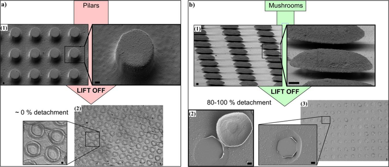
Efficiency in microdisk detachment: Pillar pattern vs Mushroom pattern: (a1) SEM micrographs of the inorganic-polymeric assembly on top of pillar pattern. (a2) Optical micrograph of the inorganic-polymeric heterostructure after the dissolution of the pillars: no detachment is obtained. (b1) SEM micrographs of the inorganic-polymeric assembly on top of mushroom pattern. (b2) SEM micrograph showing the release of a disk-shaped heterostructure. (b3) SEM micrograph after the dissolution of the mushroom template: nearly 100% microdisk detachment. Scale bars 1 μm.
So as to achieve a mushroom-shaped pattern with a pronounced undercut, photolithography in bilayer process25 has been performed spin-coating LOR10B photoresist first and S1800 (S1818, S1813 or S1805) photoresist after (Fig. 2a). The influence of the experimental conditions has been systematically analyzed to obtain the optimal mushroom sacrificial template:
Fig. 2.
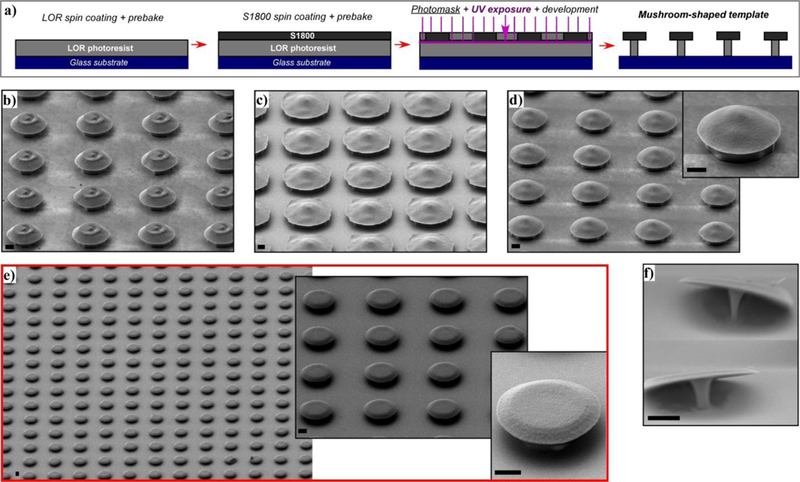
(a) Diagram of photolitography in bilayer process. SEM images of different mushroom patterns showing the effect of experimental conditions: (b) Thicker photoresist (S1818), (c) under-exposure (UV exposure t < 7s) , (d) prebake step of LOR10B (t, T > 2 min, 150 ºC), (e) optimal conditions, (f) over-development (t > 25 s). Scale bars 2 μm.
When S1818 or S1813 photoresists are used, which are around 1.5 μm and 2.5 μm thick respectively, the resulting mushroom-pattern tends to have a cone structure cap with flattened vertex (Fig. 2b). On the contrary, the thinnest S1805 photoresist (0.5 μm thick) has proved to form flat mushroom caps.
When the UV beam does not reach the interface between S1805 and the LOR10B (UV exposure t < 7s), the development of S1805 happens slowly in the unexposed zones creating irregular cap shapes (Fig. 2c).
In order to get the fastest dissolving rate in LOR10B photoresist, and therefore a large undercut, it has to be prebaked at 150 ºC for 2 min. When the prebake T and t are increased the undercut becomes less noticeable (Fig. 2d), impairing the effectiveness of the lift off process.
Fig. 2e represents a reproducible mushroom pattern obtained by an optimized single exposure-development step photolithography. It consists on prebaking LOR10B photoresist at 150 ºC for 2 min first and then the LOR10B/S1805 bilayer at 115 ºC for 60 s, use 7 s of UV exposure and 20 s of development in MF-319 (See Experimental Section). The development time should not be longer than 25 s, otherwise the stem of the mushroom becomes too narrow to hold the structure properly (Fig. 2f).
Fabrication of multifunctional inorganic-polymeric microdisks.
After the production of the mushroom-shaped template the inorganic-polymeric heterostructure is constructed on top of it. Firstly, the inorganic thin film (SiO2) is deposited on the template using Electron Beam Physical Vapor Deposition (EBPVD) (Fig. 3a); and subsequently, the polymeric multilayer (PDAC/PSS)1.5, the F-MNPs (Fe3O4 NPs functionalized with PMAO-Rhodamine123) and the PAH-Biotin polyelectrolytes are assembled using the Layer by Layer (LbL) spray deposition26 (Fig. 3b,c). The release of the disk-shaped assemblies from the substrate is carried out dissolving the mushroom pattern by MF-319 aqueous developer (Fig. 3d).
Fig. 3.
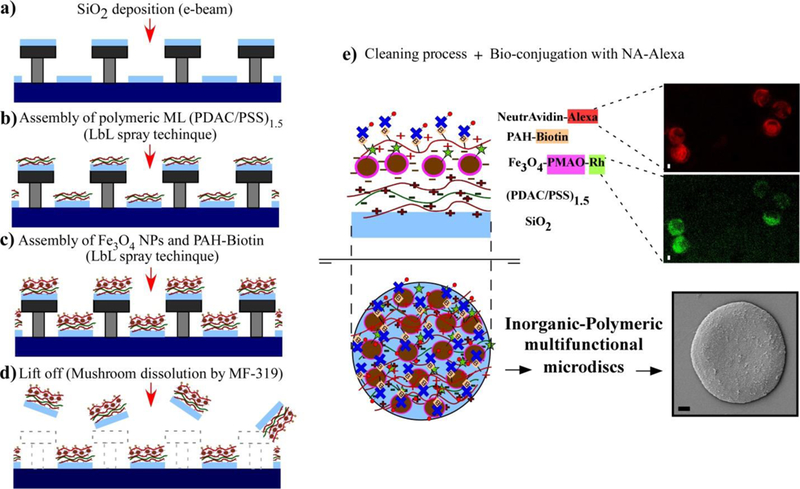
Fabrication process of inorganic-polymeric microdisks: (a) The inorganic phase (SiO2) is deposited by e-beam evaporator system. (b) The assembly of polymeric multilayers (PDAC/PSS)1.5 on top of the pattern is carried out by LbL (layer by layer) spray technique. (c) The F-MNPs (Fe3O4@PMAO-Rhodamine123) and the PAH-Biotin polyelectrolyte are also assembled using LbL spray technique. (d) The release of the disk-shaped heterostructure is accomplished by dissolving the mushroom template with an aqueous developer (MF-319). (e) After several cleaning cycles with DI H2O, the microdisks are conjugated with NA-Alexa647 for specific membrane targeting; the composition of the disks from bottom to top layer is displayed (the drawings represent cross-sectional and top views of a microdisk); fluorescence images of microdisks in water suspension at 647 (Alexa) nm and 530 nm (Rh) are shown together with a SEM micrograph of a disk facing up. Scale bars 1 μm.
The final bioconjugation step, in which NeutrAvidin is bonded to the outer layer of the assembly through Avidin-Biotin interaction (Fig. 3e), provides a versatile interface to biotinylated antibodies or ligands. As NeutrAvidin (NA) was previously conjugated with Alexa Fluor dye (see Experimental Section), the presence of NA in the microdisks can be easily confirmed by fluorescence microscopy. The fluorescence micrographs in Fig. 3e correspond to Alexa Fluor 647 (red, emission peak 665 nm) and Rhodamine 123 (green, emission peak ~ 530 nm), acting as broad markers of the microdisks and also local markers of NA and Fe3O4 F-MNPs, respectively. Fig. 3e also displays a SEM micrograph of a single microdisk (facing up) subsequent to the cleaning and bioconjugation process, together with a cross section drawing that shows the different components of the microdisk: (1) An inorganic thin film (=100 nm) of SiO2 offers support and integrity to the entire system. (2) A polymeric multilayer [(PDAC), (PSS) and (PAH-Biotin)] allows the assembly of multiple functional cargoes into the structure and acts as an interface and buffer between these cargoes, the soft target cell, and the inorganic film. (3) Cargoes such as water-soluble Fe3O4@PMAO F-MNPs provide the magnetothermal actuation, NeutrAvidin macromolecules enable attachment to the cell membrane and fluorophores (Rhodamine or Alexa Fluor Dye) mark the cargoes, track their position and distribution inside the hybrid-structure and, in our application, they also measure local temperature.3 The final composition of the microdisk from bottom to top layer can be described as follows: SiO2-film/(PDAC/PSS)1.5/Fe3O4@PMAO-Rh/PAH-biotin/NA-Alexa.
The great advantage of the approach described in Fig. 3 is its adjustability and versatility. The diameter of the disks can be changed by simply varying the dimension of the circular motifs in the photomask (See Experimental Section). The inorganic phase and thickness is deposited by EBPVD and, therefore, multiple suitable combinations can be attained without difficulty. In addition, different NPs (size, density and composition) can be assembled into the system (Figures S3 and S4, ESI†) and the PAH, supported on the last layer, can be easily conjugated with different biomolecules and fluorophores through simple amine-reactive crosslinking chemistry (see Experimental Section). Fig. 4 shows the features of two different samples: sample 1 (Fig. 4a), composed of microdisks with 8μm diameter, a SiO2 film of 200 nm thickness and Fe3O4 F-MNPs (34±3 nm) in a density of 100 NPs/μm2; and sample 2 (Fig. 4b), formed by microdisks with 5μm diameter, a Au film of 40 nm thickness and Fe3O4 F-MNPs (34±3 nm) in a density of 50 NPs/ μm2. Fig. 4a2 and b1 show the SEM micrographs of the substrate after the lift-off process where the efficiency of the process can be estimated as over 80 %. In the insets of Fig. 4a and 4b it is easy to see how the polymeric multilayer and the Fe3O4 F-MNPs are wrapping around the inorganic thin film entirely from the side facing up during the spray process, while the side that corresponds to the inner part of the mushroom cap is covered just from the edge. A thin Au film is an appropriate option due to its biocompatibility, low cytotoxicity, antibacterial activity and malleability. But in order to perform fluorescence thermometry in the microdisks SiO2 is more suitable because it is not only non-toxic and biocompatible but also transparent. Even though a SiO2 film is more fragile than a Au film, the integrity of the system can be kept intact by being gentle in the cleaning process (see Experimental Section).
Fig. 4.
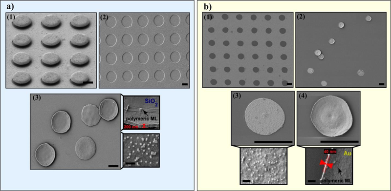
SEM images of Sample 1 showing: (a1) the mushroom pattern with the inorganic-polymeric heterostructure (60° inclination), (a2) the substrate after dissolving the mushroom-pattern, (a3) lifted off microdisks (diameter = 8 μm) composed by SiO2 thin film, polymeric multilayer and 34 nm Fe3O4 F-MNPs assembly. Top-Inset: an upside-down microdisk displaying its thickness (200 nm). Bottom-Inset: a microdisks that is facing up and shows the F-MNPs density on the surface (100 NPs/μm2). SEM images of Sample 2 showing: b1) the substrate after dissolving the mushroom-pattern, (b2) lifted off microdisks (diameter = 5 μm) composed by Au thin film, polymeric multilayer and 34 nm Fe3O4 F-MNPs assembly, (b3) a microdisk facing up, the corresponding Inset shows the F-MNPs density on the surface (50 NPs/μm2) and (b4) an upside-down microdisk, the corresponding Inset displays its thickness (40 nm). Scale bars 5 μm (scale bars in the insets 200 nm).
The effect of assembly conditions on the arrangement of ferromagnetic nanoparticles.
For biomedical magnetic hyperthermia applications, magnetite (Fe3O4) NPs are well suited, due to their biocompatibility and long clinical history.27 Typically Fe3O4 superparamagnetic nanoparticles (SP-MNPs) have been used to prevent aggregation.28 However, this limits the maximally achievable heating power of these NPs. In addition, even SP-MNPs exhibit some agglomeration in biological systems; and thus, recent research has been dedicated to elucidate the magnetic properties of MNP clusters in different biological environments.10,29,30 Alternately, stably embedding the MNPs in the inorganic-polymeric microdisks would eliminate any aggregation because the MNPs would be immobilized in a two-dimensional plane. This would permit using single domain ferromagnetic NPs of Fe3O4 (D>25 nm) which exhibit very large specific absorption rate (SAR) values under alternating magnetic field (AMF) of moderate field intensities (H>15kA/m).31 Hence, in this study, highly crystalline monodomain F-MNPs of Fe3O4 with an average diameter of 34±3 nm and octahedral morphology have been inserted into the inorganic-polymeric-assembly (Fig. 5a). These Fe3O4 F-MNPs were synthesized by thermal decomposition of iron(III) oleate (Fe[C18H33O2]3, following a recently published approach with some modifications (see Experimental Section).32 The as-synthesized hydrophobic NPs were transferred to the aqueous phase by coating them with Poly(maleic anhydride-alt-1-octadecene) (PMAO)33 (or PMAO-Rh)34, which provides a surface with carboxyl groups uniformly distributed allowing further functionalization. In distilled water with neutral pH, the ionization degree of PMAO is high and causes electrostatic repulsion between ferromagnetic NPs counteracting the magnetic dipolar interaction. However, the addition of salt immediately results in F-MNP aggregation due to the screening of the surface charges. In order to impart colloidal stability in buffers and physiological solutions a specific steric stabilization is necessary, which consists of grafting long PEG tails (5kDa) in a high density to the PMAO backbone.35 In this regard, another great advantage of the multifunctional microdisks is that the ferromagnetic NPs can be assembled homogeneously within the polymeric multilayer without the need of modifying the PMAO coating.
Fig. 5.
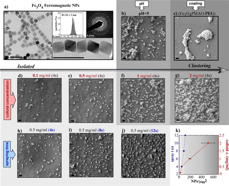
(a) TEM image of Fe3O4 F-MNPs together with the size distribution and the corresponding electron diffraction pattern; (b-j) SEM micrographs (lower magnification images in Figure S4, ESI†) of different microdiskś surfaces prepared under distinct conditions (in sample b the F-MNP colloid had pH<5, in sample c the F-MNPs were coated with PMAO-PEG, in samples d-e-f-g the concentration of the F-MNP colloid was increased from 0.1 mg/ml to 2 mg/ml, in samples h-i-j the spraying time of the F-MNPs colloid was increased from 4 s to 12 s; (k) plot summarizing the effect of the F-MNP colloid concentration and the spraying time on the number of NPs per μm2 of microdisk surface. The grey scale represents the agglomeration degree of the F-MNPs. All scale bars are 100 nm long.
A good control over the growth, roughness and uniformity of the multilayer assembly requires the choice of appropriate spraying parameters and polyelectrolyte solution conditions (see Experimental Section). Additionally, the features of the Fe3O4 F-MNP colloid and its spraying time are especially critical in the F-MNP arrangement as explained hereinafter. In Fig. 5b–j SEM micrographs of the microdiskś surfaces corresponding to different samples prepared under distinct colloidal and spraying conditions are displayed. Firstly, lowering the pH of the F-MNP solution (<5) causes protonation of the carboxyl groups and provokes a reduction of the electrostatic repulsion; similarly, the PEGylation of PMAO decreases the surface charge causing larger agglomeration between F-MNPs (Fig. 5b,c). Secondly, the density of NPs per μm2 of microdisk is increased when the concentration (c) of the F-MNP colloid is varied from 0.1 mg/ml (Fig. 5d) to 2 mg/ml (Fig. 5g) while keeping the spraying time constant (4s). However, in Fig. 3f, sample f (c = 1 mg/ml), some agglomeration is observed, being even more noticeable in Fig.3g (c = 2 mg/ml). Thirdly, varying the spraying time (from 4 to 12 s) while keeping the concentration of the colloid suspension constant (c = 0.5 mg/ml) is a very reliable approach to increase the F-MNP density on the disks with minimal clustering (Fig. 5h,i,j). Fig. 5k summarizes the former results and shows how the density of NPs/μm2 can be finely tuned by modifying the spraying time or the concentration of the F-MNP colloid.
Magnetic properties of the microdisks and the effect of nanoparticle agglomeration.
The Fe3O4 F-MNPs used in this work exhibit high saturation magnetization (MS = 76 A·m2/kgFe3O4) and excellent SAR (2140 ± 50 W/gFe3O4 at H = 36 kA/m and f = 412.5 kHz) (Figure S5 and S9, ESI†). The zero-field cooling/field-cooling (ZFC/FC) magnetization curves of these NPs (Figure S6 in ESI†) show a sharp transition at 100 K that corresponds to the well-known Verwey transition, which is a cubic to monoclinic crystallographic phase transition, characteristic of magnetite. The fact that the Verwey transition is so abrupt reflects both the low size dispersion of the F-MNPs and the good stoichiometry of the magnetite phase.36
With the aim of checking the magnetic properties of microdisks obtained under increasing spraying time, hysteresis loops at different temperatures (300, 200 and 5 K) are compared in Fig. 6. These measurements were performed by drying 40–60 μl of microdisk suspensions of samples h, i and j (in Fig. 5h,i,j) directly onto the magnetometer sample holder. The M (H) curves of Fig. 6a saturates at low fields (80 kA/m) and presents a coercive field (HC) of 44 kA/m indicating the ferromagnetic character of the NPs at RT. Notably, isothermal normalized magnetization curves are almost perfectly superimposed to each other in the whole range of temperatures. Note also that reduced remanent magnetization at 5 K approaches to 0.5, as expected in non-interacting single domains oriented at random.37 Hence, it is obvious that magnetization response to external fields is only scaled up or down dependently on the total number of F-MNP, being their intrinsic properties not influenced by dipolar interactions in this range of NP/μm2 values. These measurements allow also for testing the consistency of F-MNP density determination estimated from SEM measurements.
Fig. 6.
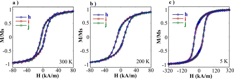
(a, b, c) Hysteresis loops at different temperatures obtained by depositing microdisk suspensions onto the quartz sample holder of the SQUID magnetometer. Samples h, i and j were prepared using different spraying times (4s, 8s and 12 s, respectively). The isothermal magnetization curves of the 3 samples almost collapse in a single curve after normalizing to the saturation magnetic moment of microdisk suspensions.
As shown in Table 1, the macroscopic estimations of F-MNP density on disk surface for samples h, i and j match very well with those values of NPs per μm2 estimated by SEM characterization (Fig. 5). The number of microdisks in the suspension was determined by a hemocytometer and the corresponding number of Fe3O4 NPs was calculated from the saturation magnetic moment of the dried suspension taking into account the Ms of the NPs (76 Am2/kg from Figure S5, ESI†). The macroscopic value of NPs per μm2 of disk is simply the number of NPs divided by the total area of microdisks (d = 8μm).
Table 1.
Saturation magnetic moments of microdisk suspensions (samples h, i and j) at RT dried directly on a quartz holder, volume taken from each suspension, microdisk concentration in the aqueous suspensions determined by hemocytometer, the macroscopic estimation of NPs/μm2 and the corresponding NPs/μm2 value from SEM characterization.
| Sample | Magnetic moment at RT (A·m2) |
Microdisk suspension V (μl) |
Microdisk C by hemocytometer (MDs/ml) |
Macroscopic estimation of NPs/μm2* |
SEM estimation of NPs/μm2 ** |
|---|---|---|---|---|---|
| h | 5.2 · 10−10 | 50 | 4.2(6) · 105 | 56±8 | 45±11 |
| i | 1.2 · 10−9 | 60 | 5(1) · 105 | 80±16 | 84±16 |
| j | 4.2 · 10−10 | 40 | 2.2(2) · 105 | 105±10 | 110±8 |
The error of the macroscopic estimation has been determined from the counting by the hemocytometer.
The error in the SEM estimation corresponds to the analysis of 5 different areas.
The effect of the F-MNP agglomeration degree on the magnetic properties of the flat hetero-assembly can be distinctly observed by mapping the magnetization switching distribution obtained from the First Order Reversal Curves (FORCs).38 In these curves, the magnetization (M) is recorded with increasing applied field (), starting from sequentially descending fields (called reversal fields ), after saturating the sample with the maximum positive field (120 kA/m in this case). In this way, a family of FORCs (200 curves) is obtained at different values (between −120 and 120 kA/m) with equal field spacing (1.2 kA/m) that fills the interior of the major hysteresis loop, as presented in the insets of Fig. 7 (and in Figure S7, ESI†). These measurements have been performed at 50 K in order to avoid thermal relaxation effects as well as to increase resolution of the FORC diagrams in affordable measurement time limits. Three dimensional contour plots of Fig. 7 represent the FORC distribution, which is calculated from the mixed second-order derivative of magnetization (Equation 1), as described in previous works:39,40
| (1) |
Fig. 7.
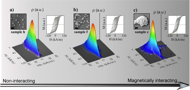
(a, b, c) FORC curves in the right insets and the corresponding three dimensional contour plots of the FORC distribution in Hc and Hb of samples h, f and c, respectively. The grey scale represents the strength of the resulting magnetic dipolar interactions. The left insets are the corresponding SEM micrographs of the samples (also in Figure 5), scale bars are 100 nm.
It is useful to perform a coordinate transformation in order to represent three dimensional contour FORC plots as a function of local coercive field (), and bias field (), given by and . For the particular case of isolated single magnetic domains, random inter-dipolar interactions produce a characteristic imprint in the diagrams that help to identify the influence of the microdisks preparation conditions on their magnetic properties. In Fig. 7a (corresponding to sample h, c=0.5mg/ml and 4s spray) it can be observed that FORC distribution collapses on a central ridge whose shape maps the coercive field distribution. The sharpness of this central ridge is quite visible also in the 2D projections of FORC distributions (presented in Figure S8a, ESI†) and reflects the absence of interparticle interactions, such as in the case of isolated chains within magnetotactic bacteria.41 However, as soon as dipolar interactions increase in more agglomerated samples, slightly in sample f (c = 1 mg/ml and 4 s spray) and more pronounced in sample c (PMAO-PEG coating, c= 0.5 mg/ml and 4 s spray), the corresponding FORC distributions (Fig. 7b and c respectively) start spreading over the base of the central ridge for positive and negative values of . This fact indicates the presence of significant interactions in sample c. In addition, the coercive field of sample c peaks at progressively lower fields, so the magnetic hysteresis becomes strongly reduced at this level of agglomeration. Considering that hysteresis loops of samples h, i, j at different temperatures are basically superimposed (as observed in Fig. 6), it can be concluded that the magnetic properties of sample i and j are almost identical to sample h and, therefore, they correspond to the magnetically non-interacting range. It means that total heating power due to each microdisk can be predictably enhanced simply by increasing the spraying time of the F-MNP colloid.
Microdisk binding and magnetothermal actuation on cells.
For efficient targetable cargo delivery as well as cellular excitation, it is imperative for the microdisks to not just be in close proximity to the cells, but to be physically attached to the cytoplasmic membrane. Chronic implantation also requires long membrane residence time of the microdisks without internalization into the cells. The cell-disk interactions were studied on HEK293 cells as well as on rat hippocampal neurons. To facilitate binding of NeutrAvidin coated microdisks, HEK cells were Paraformaldehyde (PFA) fixed and biotinylated; then a suspension of microdisks was added to the physiological buffer bath, above the cells. Fig. 8a shows microdisks in red (Alexa 647 fluorescence) in PFA fixed biotinylated HEK293 cells. To assess the stability of the microdisks binding to the cell membrane, we imaged a region of HEK cells (green fluorescent membrane marker, ChR2-GFP) with bound disks (red, Alexa 647 fluorescence) repeatedly, while continuously perfusing buffer solution over the cells (Fig. 8a). The microdisks are mostly not affected by the perfusion (washes) and remain in place.
Fig. 8.
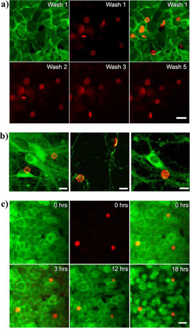
Microdisk binding. (a). Top: Disks seen by Alexa 647 (red) were attached to fixed biotinylated HEK293 cells (green). A single confluent cell layer covered the field of view. (left: cells, middle: microdisks, right: overlay). Bottom: Microdisks bound to cells were washed with two milliliters of buffer solution and a snapshot was taken after the washes. (b) Fluorescence micrographs showing microdisks (red) attached to cultured rat hippocampal neurons (green, GFP). Disks bind to the cell body (soma) as well as the neurites (middle panel). (c) The microdisks resist endocytosis: Timestamped panels show membrane labeled (green, GPI-GFP) HEK2 93T cells with attached microdisks (red, Alexa 647). The residence time of microdisks on the cell membrane spans at least 18 hours.
To determine the feasibility of microdisks actuators for neuroscience, we bound microdisks to PFA fixed rat hippocampal neurons in culture (Fig. 8b). The disks bind to the cell body, but also to proximal and distal neuronal processes. The microdisks conform to the topography of the cells and are found to attach typically to cells by their flat face. Previous studies have shown that the local particle curvature at the point of contact dictates whether cells will engulf the particle. It has been demonstrated that flat particles attached to macrophages are not internalized for over 12 h.17 We assessed the residence time of the microdisks on living biotinylated HEK293 cells incubated at 37 ºC. As it can be seen in Fig. 8c the microdisks remained attached to cell surfaces without internalization for at least 18 hours. This stable and lasting attachment between cells and multifunctional microdisks opens up the opportunity of using long-term sub-cellular implants for magnetothermal therapies or neuromodulation.
The potential use of these devices in biomedicine depends on efficient heating capacity once attached to cells. To quantify the local heating in the F-MNP containing microdisks during application of alternating magnetic field (AMF), we used fluorescence thermometry.3 The fluorescence lifetime of Alexa Fluor 647, and hence its fluorescence intensity, decreases with temperature increase. Over a limited region of temperature change, the fluorescence intensity decreases linearly, 0.46 % for 1 °C increase (Figure S10, ESI†). We integrated Alexa Fluor 647 in the NeutrAvidin molecules, which are placed in the superficial layer of the microdisk and allow the biotin-avidin binding to cells (see zoomed area in Fig. 9a). The fluorescence signal was recorded using an inverted microscope with sCMOS camera and LED illumination, while the AMF (30 kA/m @ 412.5 kHz) was applied by a coil placed over the dish (Fig. 9a). The heating rate of the cell-attached microdisks with varying F-MNP density ranged from 0.52 ± 0.16 °C/s to 1.76 ± 0.534 °C/s, increasing linearly with F-MNP densities from 40 NPs/μm2 to 120 NPs/μm2 (Fig. 9b,c). A linear dependence between the heating rate in the disks and the F-MNP density is expected for non-interacting MNP as their heating powers independently add. If the F-MNP showed magnetic dipolar interactions we would expect a deviation from this linear dependence. While this may still occur at higher NP densities, we did not observe any interactions at 120 NPs/μm2 which corresponds to a center-center distance between NP of 103 nm. The volume heating rate in a suspension of the same Fe3O4 F-MNPs (2 mg/ml, or 16 NPs/μm3) was about 1 °C/s (at H = 36 kA/m, f = 412.5 kHz) (see Figure S9, ESI†). As the field in the disks experiment was 20% lower and fixation of the NPs in the disks removes the Brownian mechanism, it is expected that the measured heating per NP in the disks should be about half of that in suspension. However, a quantitative comparison is currently impossible as it is unknown how much water is heated around each microdisk. Recently, we showed that different, smaller SP-MNPs at 400 NPs/μm2 would heat at 0.5 °C/s and were able to elicit action potentials in neurons leading to changes in animal behavior.3 Hence, the microdisks here are perfectly suitable to trigger fast firing in neurons repeatedly and reproducibly. Furthermore, the microdisks with high density of F-MNPs can be used to increase the temperature in cancer cells between 40 and 45 °C in less than 10 s so as to selectively induce apoptosis rather than having to heat and ablate an entire tissue.
Fig. 9.

Microdisk heating on cells. a) Illustration of the set up for fluorescence thermometry on magnetothermally heating microdisks on the cell membrane. Zoom-in shows the attachment scheme of microdisks to the cell membrane. b) Fluorescence intensity time traces (bleach corrected and normalized) of the Alexa Fluor 647 dye on the microdisks during AMF application (grey bar, 0 – 5 s) show results from two microdisk samples with different F-MNP densities (orange and turquoise colored). Left axis (blue) shows the temperature change obtained from the fluorescence changes (shown at right axis (red)) (Figure S10, ESI†), shows the calibration of the temperature dependent fluorescence). c) Summary plot of heating rates (mean ± sem, n = 4 disks per sample) obtained from fluorescence thermometry in AMF (30 kA/m at 412.5 kHz) heated microdisks of varying F-MNP densities (NPs per μm2 of disk surface). All recordings were done on disks attached to HEK293 cells. Data is presented as mean ± sem and fitted linearly (red dashed line). The data was fitted with a line (bx + a; a = 0.013 ºC·s−1 and b = 0.013 ºC·μm2·s−1).
CONCLUSIONS
In conclusion, we have engineered a multifunctional inorganic-polymeric microdisk platform, loaded with F-MNPs, fluorophores and biomolecules. To this end, we have developed a novel approach consisting on the fabrication of a mushroom-shaped sacrificial template that allows to assemble the different inorganic-organic components in disk-like uniform arrangements and enables to release them from the substrate with high efficiency. The versatility of this approach makes possible to finely customize the disk diameter, thickness, inorganic phase and NP density per μm2 of disk surface. Moreover, we have succeeded in producing a homogenous assembly of Fe3O4 F-MNPs with minimal NP agglomeration and devoid of dipolar interactions. The disks allow to deliver the F-MNPs to cell membrane in a known arrangement, free of undesirable clustering effects, so providing close control over their in-situ physical properties. We have shown that the heating capacity of the F-MNPs is only slightly reduced by being embedded in the microdisk when compared to the F-MNP suspension. F-MNP loaded disks heat significantly faster than disperse SP-MNPs on the cell membrane, and the attachment of the microdisks to the cells is persistent and resists endocytosis. Therefore, the F-MNP loaded microdisks provide ideal long-lasting sub-cellular implants for wireless magnetic remote cell control.
EXPERIMENTAL SECTION
Materials
Iron (III) chloride hexahydrate was purchased from Across (99%) and sodium oleate from TCI America (97%). Neutravidin protein, Alexa Fluor 647-NHS ester and Biotin-NHS ester were purchased from Thermo Fisher Scientific. LOR photoresist and MF-319 developer were obtained from Microchem and S1805 photoresist was obtained from Microposit. Other reagents and chemicals were purchased from Sigma-Aldrich and used as received unless otherwise stated.
Synthesis of ferromagnetic NPs
Ferromagnetic Fe3O4 NPs, with a diameter of 34±3 nm, were prepared by thermal decomposition of iron (III) oleate (5 mmol Fe[C18H33O2]3) under N2(g), in a 2:1 mixture of organic solvents (10 ml 1-Octadecene + 5 ml Benzyl ether) using oleic acid (10 mmol) as surfactant, a heating rate of 3 ºC/min and a final T of 330 K and keeping the reflux for 30 min. 5 ml THF and 10 ml EtOH were added to the final mixture and centrifuged for 30 min at 16 000g (9500rpm). The supernatant was removed and 10 ml of Hexane were added to the pellet formed in the bottom. After dispersing the colloid properly, 10 ml EtOH were added and the mixture was again centrifuged and the supernatant removed (this process was repeated twice). Finally, CHCl3 was added and the stock solution was stored in the fridge. The F-MNPs were transferred to the aqueous phase by coating them with PMAO33 or PMAO-Rhodamine 12334.
Microdisk preparation
-Mushroom template (photolithography in bilayer process):
One inch2 glass substrates were cleaned in an ultrasonic bath consecutively with acetone, EtOH and H2O, were dried with N2(g) and placed on a hot plate (200 ºC) for 5 min. Clean substrates were loaded into a spin-coating system (Brewer Science CEE-200) and covered with LOR10B positive photoresist (MicroChem). The substrates were spun at 2500 rpm for 45 s, removed, and immediately placed on a hot plate at 150 ºC for 2 min (which gives rise to the fastest undercut rate). Then the substrates were loaded again into the spin-coater, covered with S1805 (Microposit), spun at 2500 rpm for 60 s and transferred to a hot plate for a prebake process at 115 ºC for 60 s. A specially designed chromium-quartz photomask with different regions containing different chromium diameter circles (5 and 8 microns) was used for UV exposure. A Karl Süss MJB3 Mask Aligner was used to bring the photoresist-coated substrate into direct contact with the photomask. The exposure was done at 365nm (350 Watt UV Hg lamp) for 7 seconds so that the UV reaches the interface of both photoresists (for a successful undercut the LOR10B needs to be unexposed). Next, the substrates were dipped and gently shaken in MF319 developer solution for 20 s. The developer dissolved the exposed portions of the S1805 photoresist and when it reached the LOR10B layer, it isotropically etched at a fast rate, which resulted in a pronounced undercut structure. Finally, the substrates were rinsed with RODI water, and dried with N2 (g). This protocol gave rise to a perfectly reproducible mushroom-shaped pattern of 8μm or 5 μm in diameter (depending on the mask region that was used).
- Electron Beam Physical Vapor Deposition
The BOC Edwards Auto 500 electron-beam evaporation system was used for SiO2 and Au thin film depositions (High voltage: 4.77 kV, Beam filament: 1.5 mA, deposition rate: 0.2nm/s).
-PAH-Biotin (1%) conjugation
5.7 mg (10 mmol monomer) PAH (900kDa) were dissolved in 8 ml D.I H2O and then 1 ml SBBS (50 mM pH=8.4) was added (solution 1). Then, 2 mg (0.05 mmol) Biotin-NHS ester were dissolved in 100 μl DMSO and diluted with 900 μl D.I H2O (solution 2); in order to conjugate at least 1% of PAH monomers (0.1 mmol) 5 fold biotin was used. Solution 2 was added to solution 1, the mixture was gently vortexed and incubated for 4 hours at RT. The resulting solution was centrifuged with centrifugal filters (100 kDa) at 3.500 g for 8 min to remove the free biotin and diluted to 5 ml with D.I H2O (the process was repeated 3 times). The stock solution (0.02M based on monomer) was stored in the refrigerator.
-LbL spray technique
By this technique 5 monolayers were sprayed [(PDAC/PSS)1.5(Fe3O4@PMAO-Rh)1(PAH-biotin)1] and the experimental conditions for optimal results were found to be: ▪Spraying-Draining-Rinse timing in each monolayer: Spray (4s)-Draining (21s) -Rinse spray(20s)- Draining (15s). ▪Substrate spray nozzle distance: 5 cm. ▪Concentration of the polyelectrolyte solutions (based on monomer): 0.01 M. ▪Concentration of salt in the polyelectrolyte solutions: [NaCl]= 0.15 M. ▪ pH of the polyelectrolyte solution: PDAC (150 kDa) and PSS (70 kDa) pH=6.5; Fe3O4@PMAO pH=6.5; PAH-Biotin pH=8.4 ▪Spraying rate: 0.125 ml/s.
-Lift off process
The substrate with the mushroom-shaped pattern and the inorganic-polymeric multilayer (SiO2-film/(PDAC/PSS)1.5/Fe3O4@PMAO-Rh/PAH-biotin) was dipped in 2 ml MF-319 developer and sonicated for 20 s. In this process the mushroom structure (LOR10B and S1805 photoresists) was dissolved and the microdisks were released into the aqueous developer (MF-319).
-Cleaning
The 2 ml microdisks suspension in MF-319 were passed through a 20 μm cell strainer (twice) in order to eliminate bigger aggregates. The resulting suspension was centrifuged at 2.000 g for 2 min, the supernatant was removed and the pellet was redispersed in 500 μl of clean D.I water (by pipetting up and down slowly). The resulting suspension was centrifuged again at 2.000 g for 2 min, the supernatant removed and 500 μl clean D.I H2O added (twice). The concentration of microdisks (8 μm in diameter) in 500 μl stock suspension (for 100% lift off) would be 5·106 disks/ml. It was confirmed by hemocytometer that typically the lift off was above 80%.
-Bioconjugation
▪Neutravidin+Alexa 647conjugation:
For a labeling ratio of NA:Alexa=1:5, 4.2 μl of Alexa Fluor 647 NHS Ester (10 mg/ml in DMSO) was added on top of 200 μl of NA (2 mg/ml in PBS 1x) and the mixture was shaken gently for 2 hours. Centrifuge filter of 10 kDa was used until the filtrate cleared out (4 runs at 8000 g for 5 min). The retentate was collected and re-suspended in 400 μl PBS, the 1mg/ml NA-Alexa stock solution and a 0.01mg/ml NA-Alexa dilution in D.I H2O were stored in the fridge.
▪Microdisks + NA-Alexa conjugation:
4·106 NA are needed to cover the surface of one microdisk with a d=8μm. To cover the surface of 2·105 disks (10% of the total amount in one sample with 80% lift off) 4 fold NA was used. 32 μl NA-Alexa (0.01mg/ml stock) were added to 50 μl microdisks suspension (c=4·106 disks/ml) and incubated for 20 min at RT. Centrifuge filter of 300 kDa was used (3 runs at 2000 g for 1.5 min) to remove free NA-Alexa. The concentration of NA-Alexa conjugated disks in 400 μl stock suspension was around 5·105 disks/ml.
TEM characterization
TEM micrographs of the Fe3O4@PMAO F-MNPs in water colloid were obtained using a JEOL JEM 2010 with an accelerating voltage of 200KV, and a point resolution of 0.19 nm, which provides morphology images and the corresponding crystal structures by selected-area electron diffraction.
SEM characterization
Focused Ion Beam Scanning Electron Microscope (FIB-SEM) - Carl Zeiss AURIGA CrossBeam (HT=2 kv, WD=5mm) was used for the characterization of photolithographic patterns, and the detailed analysis of the microdiskś thickness, diameter, surface roughness and NP density per μm2 of surface. The microdisks’ thickness and morphology were investigated by tilting samples to 60 or 80 degrees.
Magnetic Characterization
The M(H), M(T) and the first-order reversal curve (FORC) measurements were performed using a SQUID magnetometer (MPMS3, Quantum design).
In-vitro studies
-Loading microdisks on cells
HEK293 cells were plated on 12 mm cover glass (Carolina) in 24 well plates, per standard protocols. Wild type cells or cells expressing eGFP membrane markers were used (see Supporting Information). Experiments were performed when the cells were ~80% confluent. For the wash resistance test or cell-attached microdisk heating tests, the cells were first fixed with 4% Paraformaldehyde (PFA) (in ice cold PBS, 20 minutes). The cells were then biotinylated and the excess of biotin was washed off before infusing the microdisk suspension. Ten minutes were allowed for the microdisks to settle and bind, before the buffer solution was aspirated and added back to the dish. This allowed for the microdisks settled on glass to be resuspended in the bath, while the plasma membrane bound microdisks remained attached. This process was repeated a few times and after each repetition the same field of view was imaged. When no further microdisk displacement was observed, the microdisks were deemed bound to cells.
Rat hippocampal cultures (obtained from E16 Sprague Dawley rat pups; experiment day: DIV 14) were similarly fixed and biotinylated for microdisk conjugation. For endocytosis studies, living HEK cells growing on glass cover slips were transferred to an imaging chamber and a physiological buffer solution with suspended microdisks was added.
-Imaging
For all imaging purposes (except confocal microscopy) a Zeiss Axioscope Observer A1.0 inverted microscope was used. Collimated LED light sources (Thorlabs) and 40x objective lens were used with appropriate optical filters (Semrock) for fluorescence microscopy, and the images were acquired using μManager42 software driving an Andor neo sCMOS camera. Confocal microcopy images were acquired at UB North Campus Confocal Imaging Facility using a Zeiss LSM 710 microscope and images were processed using the ZEN software.
-Fluorescence thermometry
A custom coil (water cooled, 5 turns, 5 cm diameter) powered by MSI automation induction heating system was used for AMF generation. The coil was placed over the sample holder, mounted on the XY stage of the microscope. The r.m.s field strength was 30 kA/m at 412.5 kHz for all heating experiments. The focal plane was kept steady during time series image acquisition, by incorporating a commercial autofocus (Motion X) in the optical path. Global temperature in the bath above the cells was measured using an optical temperature probe (Neoptix), which is unaffected by magnetic fields.
Analysis, for extraction of heating data was done in Image J (FIJI) and IgorPro 7. Mean intensity data from the Region of Interest (ROI) corresponding to individual microdisks were extracted from each time frame image using FIJI. The data was sequentially plotted, background subtracted and normalized for analysis in IgorPro.
-Thermal calibration of dye on the microdisks
For thermal calibration, fluorescence microscopy of microdisks loaded on HEK293 cells was done while the buffer above was heated or cooled. One second pulsed illumination was used to record fluorescence intensity at various temperature points. The intensity values were then plotted against the temperatures and averaged over multiple runs. Linear fit of the data gave the calibration slope.
Supplementary Material
ACKNOWLEDGEMENTS
Dr. I. Castellanos-Rubio thanks the Basque Government for the financial support provided through a postdoctoral fellowship. We thank Jonathan M Mcmahon (The Electrical Engineering Cleanroom at UB) for assistance with cleanroom equipment. We thank Alan Siegel (UB North Campus Imaging Facility, Department of Biological Sciences) for assistance with confocal imaging. This work was partially supported by institutional funding from the Ministry of Economy and Competitiveness and Basque Government under Projects MAT2016-78266-P and GIC-IT-570-13.
Footnotes
SUPPORTING INFORMATION
Electronic supplementary information (ESI) available. See DOI:10.1039/c8nr03869d Additional SEM micrographs, Magnetic characterization, SAR measurements, Normalized fluorescence change vs temperature (PDF).
Conflicts of interest
The authors declare no conflict of interest.
REFERENCES
- 1.Huang H, Delikanli S, Zeng H, Ferkey DM and Pralle A, Nat. Nanotechnol., 2010, 5, 602–606. [DOI] [PubMed] [Google Scholar]
- 2.Chen R, Romero G, Christiansen MG, Mohr A and Anikeeva P, Science, 2015, 347, 1477–80. [DOI] [PubMed] [Google Scholar]
- 3.Munshi R, Qadri SM, Zhang Q, Castellanos Rubio I., del Pino P and Pralle A, Elife, 2017, 6, 1–26. [DOI] [PMC free article] [PubMed] [Google Scholar]
- 4.Mannix RJ, Kumar S, Cassiola F, Montoya-Zavala M, Feinstein E, Prentiss M and Ingber DE, Nat. Nanotechnol, 2008, 3, 36–40. [DOI] [PubMed] [Google Scholar]
- 5.Wheeler MA, Smith CJ, Ottolini M, Barker BS, Purohit AM, Grippo RM, Gaykema RP, Spano AJ, Beenhakker MP, Kucenas S, Patel MK, Deppmann CD and Guler AD, Nat. Neurosci, 2016, 19, 756–761. [DOI] [PMC free article] [PubMed] [Google Scholar]
- 6.Tay A and Di Carlo D, Nano Lett, 2017, 17, 886–892. [DOI] [PubMed] [Google Scholar]
- 7.Di Corato R, Espinosa A, Lartigue L, Tharaud M, Chat S, Pellegrino T, Ménager C, Gazeau F and Wilhelm C, Biomaterials, 2014, 35, 6400–6411. [DOI] [PubMed] [Google Scholar]
- 8.Amiri H, Bordonali L, Lascialfari A, Wan S, Monopoli MP, Lynch I, Laurent S and Mahmoudi M, Nanoscale, 2013, 5, 8656–65. [DOI] [PubMed] [Google Scholar]
- 9.Shen H, Tong S, Bao G and Wang B, Phys. Chem. Chem. Phys, 2014, 16, 1914–20. [DOI] [PMC free article] [PubMed] [Google Scholar]
- 10.Levy M, Wilhelm C, Luciani N, Deveaux V, Gendron F, Luciani A, Devaud M and Gazeau F, Nanoscale, 2011, 3, 4402–4410. [DOI] [PubMed] [Google Scholar]
- 11.Lévy M, Wilhelm C, Devaud M, Levitz P and Gazeau F, Contrast Media Mol. Imaging, 2012, 7, 373–383. [DOI] [PubMed] [Google Scholar]
- 12.Zolnik BS, González-Fernández Á, Sadrieh N and Dobrovolskaia MA, Endocrinology, 2010, 151, 458–465. [DOI] [PMC free article] [PubMed] [Google Scholar]
- 13.Hillaireau H and Couvreur P, Cell. Mol. Life Sci, 2009, 66, 2873–2896. [DOI] [PMC free article] [PubMed] [Google Scholar]
- 14.Chithrani BD, Ghazani AA and Chan WCW, Nano Lett, 2006, 6, 662–668. [DOI] [PubMed] [Google Scholar]
- 15.Sahay G, Alakhova DY and Kabanov AV, J. Control. Release, 2010, 145, 182–195. [DOI] [PMC free article] [PubMed] [Google Scholar]
- 16.Summers HD, Rees P, Wang JT-W and Al-Jamal KT, Nanoscale, 2017, 9, 6800–6807. [DOI] [PubMed] [Google Scholar]
- 17.Champion JA and Mitragotri S, Proc. Natl. Acad. Sci, 2006, 103, 4930–4934. [DOI] [PMC free article] [PubMed] [Google Scholar]
- 18.Doshi N, Swiston AJ, Gilbert JB, Alcaraz ML, Cohen RE, Rubner MF and Mitragotri S, Adv. Mater, 2011, 23, H105–H109. [DOI] [PubMed] [Google Scholar]
- 19.Muro S, Garnacho C, Champion JA, Leferovich J, Gajewski C, Schuchman EH, Mitragotri S and Muzykantov VR, Mol. Ther, 2008, 16, 1450–1458. [DOI] [PMC free article] [PubMed] [Google Scholar]
- 20.Anselmo AC, Gilbert JB, Kumar S, Gupta V, Cohen RE, Rubner MF and Mitragotri S, J. Control. Release, 2015, 199, 29–36. [DOI] [PubMed] [Google Scholar]
- 21.Zhang H, Fujii M, Okamura Y, Zhang L and Takeoka S, Appl. Mater. Interfaces, 2016, 8, 16296–16302. [DOI] [PubMed] [Google Scholar]
- 22.Swiston AJ, Gilbert JB, Irvine DJ, Cohen RE and Rubner MF, Biomacromolecules, 2010, 11, 1826–1832. [DOI] [PMC free article] [PubMed] [Google Scholar]
- 23.Zhang P and Guan J, Small, 2011, 21, 2998–3004. [DOI] [PubMed] [Google Scholar]
- 24.Liu S, Deng R, Shen L, Xie X and Zhu J, Macromolecules, 2015, 48, 5944–5950. [Google Scholar]
- 25.Yi H, Kang M, Kwak MK and Jeong HE, Appl. Mater. Interfaces, 2016, 8, 22671–22678. [DOI] [PubMed] [Google Scholar]
- 26.Lee KK and Ahn CH, ACS Appl. Mater. Interfaces, 2013, 5, 8523–30. [DOI] [PubMed] [Google Scholar]
- 27.van Landeghema FKH, Maier-Hauffb K, Jordanc A, Hoffmannd K-T, Gneveckowc U, Scholzc R, Thiesenc B, Brücke W and von Deimling A, Biomaterials, 2009, 30, 52–59. [DOI] [PubMed] [Google Scholar]
- 28.Al-jamal KT, Bai J, Wang JT, Protti A, Southern P, Bogart L, Heidari H, Li X, Cakebread A, Asker D, Al-jamal WT, Shah A, Bals S, Sosabowski J and Pankhurst QA, Nano Lett, 2016, 16, 5652–5660. [DOI] [PubMed] [Google Scholar]
- 29.Tan R, Carrey J and Respaud M, Phys. Rev. B, 2014, 1–25. [Google Scholar]
- 30.Jeon S, Hurley KR, Bischof JC, Haynes CL and Hogan CJ, Nanoscale, 2016, 8, 16053–16064. [DOI] [PubMed] [Google Scholar]
- 31.Muela A, Muñoz D, Martín-Rodríguez R, Orue I, Garaio E, de Cerio Abad Díaz A., Alonso J, García JÁ and Fdez-Gubieda ML, J. Phys. Chem. C, 2016, 120, 24437–24448. [Google Scholar]
- 32.Chen R, Christiansen MG, Sourakov A, Mohr A, Matsumoto Y, Okada S, Jasano A and Anikeeva P, Nano Lett, 2016, 16, 1345–1351. [DOI] [PubMed] [Google Scholar]
- 33.Di Corato R, Quarta A, Piacenza P, Ragusa A, Figuerola A, Buonsanti R, Cingolani R, Manna L and Pellegrino T, J. Mater. Chem, 2008, 18, 1991–1996. [Google Scholar]
- 34.Menendez-Miranda M, Costa-Fernández JM, Encinar JR, Parak WJ and Carrillo-Carrion C, Analyst, 2016, 141, 1266–1272. [DOI] [PubMed] [Google Scholar]
- 35.Yu WW, Chang E, Falkner JC, Zhang J, Al-Somali AM, Sayes CM, Johns J, Drezek R and Colvin VL, J. Am. Chem. Soc, 2007, 129, 2871–9. [DOI] [PubMed] [Google Scholar]
- 36.Fdez-gubieda ML, Muela A, Alonso J, Garci A, Barandiara M and Ferna R, ACS Nano, 2013, 7, 3297–3305. [DOI] [PubMed] [Google Scholar]
- 37.Stoner EC and Wohlfarth EP, Philos. Trans. R. Soc. A Math. Phys. Eng. Sci, 1948, 240, 599–642. [Google Scholar]
- 38.Dumas RK, Li CP, Roshchin IV, Schuller IK and Liu K, Phys. Rev. B - Condens. Matter Mater. Phys., 2007, 75, 1–5. [Google Scholar]
- 39.Egli R, Chen AP, Winklhofer M, Kodama KP and Horng C-S, Geochemistry, Geophys. Geosystems, 2010, 11, 1–22. [Google Scholar]
- 40.Kumari M, Widdrat M, Tompa É, Uebe R, Schüler D, Pósfai M, Faivre D and Hirt AM, J. Appl. Phys, 2014, 116, 124304–1-6. [Google Scholar]
- 41.Huízar-Félix AM, Muñoz D, Orue I, Magén C, Ibarra A, Barandiarán JM, Muela A and Fdez-Gubieda ML, Appl. Phys. Lett, 2016, 108, 63109–1-5. [Google Scholar]
- 42.Edelstein AD, Tsuchida MA, Amodaj N, Pinkard H, Vale RD and Stuurman N, J. Biol. Methods, 2014, 1, 1–10. [DOI] [PMC free article] [PubMed] [Google Scholar]
Associated Data
This section collects any data citations, data availability statements, or supplementary materials included in this article.


