Abstract
Purpose
Localizing lung tumors during treatment delivery is critical for managing respiratory motion, ensuring tumor coverage, and reducing toxicities. The purpose of this project is to develop a real‐time system that performs markerless tracking of lung tumors using simultaneously acquired MV and kV images during radiotherapy of lung cancer with volumetric modulated arc therapy.
Method
Continuous MV/kV images were simultaneously acquired during dose delivery. In the subsequent analysis, a gantry angle‐specific region of interest was defined according to the treatment aperture. After removing imaging artifacts, processed MV/kV images were directly registered to the corresponding daily setup cone‐beam CT (CBCT) projections that served as reference images. The registration objective function consisted of a sum of normalized cross‐correlation, weighted by the contrast‐to‐noise ratio of each MV and kV image. The calculated 3D shifts of the tumor were corrected by the displacements between the CBCT projections and the planning respiratory correlated CT (RCCT) to generate motion traces referred to a specific respiratory phase. The accuracy of the algorithm was evaluated on both anthropomorphic phantom and patient studies. The phantom consisted of localizing a 3D printed tumor, embedded in a thorax phantom, in an arc delivery. In an IRB‐approved study, data were obtained from VMAT treatments of two lung cancer patients with three electromagnetic (Calypso) beacon transponders implanted in airways near the lung tumor.
Result
In the phantom study, the root mean square error (RMSE) between the registered and actual (programmed couch movement) target position was 1.2 mm measured by the MV/kV imaging system, which was smaller compared to the MV or kV alone, of 4.1 and 1.3 mm, respectively. In the patient study, the mean and standard deviation discrepancy between electromagnetic‐based tumor position and the MV/KV‐markerless approach was −0.2 ± 0.6 mm, 0.2 ± 1.0 mm, and −1.2 ± 1.5 mm along the superior‐inferior, anterior‐posterior, and left‐right directions, respectively; resulting in a 3D displacement discrepancy of 2.0 ± 1.1 mm. Poor contrast around the tumor was the main contribution to registration uncertainties.
Conclusion
The combined MV/kV imaging system can provide real‐time 3D localization of lung tumor, with comparable accuracy to the electromagnetic‐based system when features of tumors are detectable. Careful design of a registration algorithm and a VMAT plan that maximizes the tumor visibility are key elements for a successful MV/KV localization strategy.
Keywords: Calypso, intrafraction motion management, lung, MV/KV imaging
1. Introduction
Respiratory motion of lung tumors during radiotherapy has long been the major cause of large margins added on the gross tumor volume (GTV), and thus a source of unnecessary radiation delivered to surrounding healthy tissues. Localizing lung tumors in real time has been intensively investigated for managing respiratory motion to ensure tumor coverage while reducing toxicities. Gantry‐mounted MV and kV imaging systems have been the primary equipment deployed to detect the tumor or implanted fiducials during delivery. Although significant progress has been made in tracking implanted fiducials,1, 2, 3, 4, 5, 6, 7, 8 technical transfer from research laboratory to routine clinic has met resistance, often due to concerns of the morbidity associated with the implantation of fiducials.9 Directly localizing tumors without the implanted fiducials is more desirable and remains the ultimate goal.10, 11, 12, 13, 14, 15, 16, 17, 18, 19, 20 The major obstacle of markerless tracking is the overlap of tumor with underlying normal structures which very often obscure the appearance of tumor in the projection images. In fact, this contributed up to 45% of failures in kV image‐based tracking,17 and even worse, 53% with the MV system.18 MV and kV imaging systems on conventional linacs are orthogonal to one another. Simultaneously acquired MV/kV projections are complimentary to each other and provide more opportunities to capture the tumor. A combination of the two provides robust real‐time 3D localization results, and has become an indispensable tool for hypofractionated prostate treatment with volumetric modulated arc therapy (VMAT) at our institution.21 In this paper, we investigate the feasibility of extending the application of MV/kV images to tracking of lung tumors during a VMAT delivery.
Validation experiments of tracking are commonly performed with fiducial markers implanted inside an anthropomorphic phantom, which often yields excellent agreement between calculated and programmed motion traces. A limitation, however, is that the actual tumor size, complicated shape, and relative contrast between the tumor and surrounding environment are absent, although these factors are the main contribution to clinical uncertainties in localization. Construction of an anthropomorphic thorax phantom has been implemented via 3D printing using an actual patient's CT scan,22 which provides a more realistic means of verifying localization accuracy. We implemented a simpler and less expensive version of this technique in our institution for this purpose in the present study. Furthermore, we have simultaneously collected tumor motion traces via the Calypso electromagnetic tracking system and MV/kV radiographic images on a TrueBeam linac (both systems from Varian Medical System, Palo Alto, CA, USA) during actual VMAT treatments of lung cancer patients. With these rare but valuable data, we are able to cross‐validate the Calypso and MV/kV systems in vivo for the first time, and report on the feasibility and localization accuracy of MV/kV tracking in both phantom and patient studies.
2. Materials and method
2.A. Phantom studies
2.A.1. Phantom design
To simulate actual lung tumors with irregular shapes, we selected a lung stereotactic body radiotherapy (SBRT) patient and used the planning CT to construct a 3D phantom of the lung tumor. The tumor of this patient projected on a setup kV image is illustrated in Fig. 1. The patient's CT scan and contoured structure set were anonymized and saved in DICOM files. The Computation Environment for Radiotherapy Research (CERR)23 was utilized to process the DICOM files, and generate binary bitmaps of the tumor contour, which was subsequently converted into the appropriate format for Voxel Print (Stratasys Ltd, Rehovot, Israel). A Stratasys Objet260 Connex3 printer, controlled by Voxel Print for the novel PolyJet printing technology, was used to print the 3D tumor voxel by voxel [blue objects in Fig. 1(e)]. The printing material is VeroCyan with a density of 1.17–1.18 g/cc. The printed tumors were attached to a bottle filled with 1 l of water, simulating the medial structures inside the body, and fixed at the center of a clear thorax phantom [Fig. 1(a)–1(c)]. A CT scan of the phantom was acquired, imported into Eclipse, and the 3D printed tumor was segmented for treatment planning. A 200° conformal arc plan with MLC leaves opened 5 cm around the tumor (removing the effect of MLC blocking the tumor) and delivering 360 MU at a dose rate of 600 MU/min was created. This rotational plan was converted into an Extensible Markup Language (XML) file. Longitudinal couch motions along the superior‐inferior (SI) direction following the mathematical respiratory model proposed by Lujan24 (2 cm amplitude, 4 s period, and power of 3) were added to the XML file.
Figure 1.
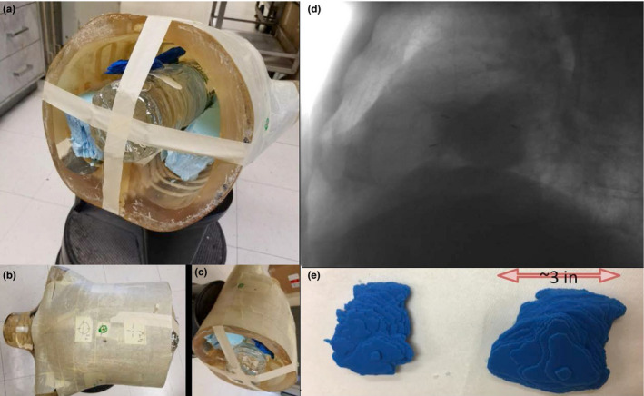
Creation of realistic lung phantom via 3D printing. See text for description of panels. [Color figure can be viewed at wileyonlinelibrary.com]
At the day of experiment, a kV cone‐beam CT (CBCT) with 200° rotation was acquired to set up the static phantom to the intended treatment position via an online manual registration to the planning CT. The XML file with programmed motion was delivered in the Developer mode on a TrueBeam linear accelerator. During irradiation, continuous MV and kV images using the high‐resolution image mode were acquired at a frequency of 9.5 and 5 Hz, respectively, via a workstation connected to the TrueBeam linac and running proprietary software iToolsCapture (provided by Varian through a research agreement). MV and kV radiographs were paired by matching the time stamp stored in the image headers.
2.A.2. Registration
Conventionally, image tracking is performed by registering the MV/kV images to templates created using the planning CT images within a specific respiratory phase to minimize the motion artifact.21 Since the phantom was well positioned with the guidance of a setup CBCT and in the context of intrafractional tumor tracking, we designed a simpler approach that directly registers the MV/kV images acquired during treatment to the CBCT projections at the same gantry positions. To account for the differences in gantry direction during the CBCT scan (clockwise rotation of 200°) and the partial arc treatment (counterclockwise rotation), a portion of the CBCT projections was rotated 180° around the SI axis to match the treatment images. The region of interest (ROI) for registration was defined as a box enclosing the tumor with a 1‐cm margin. The initial image alignment for each registration was selected as the tumor position calculated at the previous gantry angle. In addition, a capture range of 3 mm in the registration was applied to limit the range of motion between adjacent MV/kV pairs. A simplex optimization algorithm served to maximize an objective function of normalized cross‐correlation between ROIs:
| (1) |
where is the objective function, is a 2D translation inside the beams eye view (BEV), is the CBCT projection, and is the MV or kV image. Two‐dimensional shifts within the MV‐ and kV‐BEV were separately obtained.
Within the orthogonal and rotational coordinates of the MV/KV imaging system, the 2D shifts obtained independently from the MV‐ and kV‐BEV share the common motion component along the SI direction. Significant discrepancies sometimes exist between the registrations resulting from MV and kV images. Instead of simply averaging the SI registration results to minimize the localization uncertainty, we investigated the feasibility of using contrast‐to‐noise ratio (CNR) as guidance to improve the localization accuracy. At each gantry angle, CNR was calculated between the tumor at its expected location and the surrounding background for the MV and kV projections separately. The image modality with higher CNR was weighted more heavily. The registration algorithm was modified to simultaneously match the MV and kV projections to their CBCT counterparts following:
| (2) |
where θ is the gantry angle. After the 3D components in the MV/kV imaging coordinate system were derived, a rotational transformation was applied to convert them to room coordinates, and generate motion traces along the SI, anterior‐posterior (AP) and left‐right (LAT) directions. The calculated trace was compared with the actual instantaneous couch position, which was embedded in the image header and retrieved automatically. Root mean square errors (RMSE) between registered and actual tumor positions were calculated to evaluate the overall tracking accuracy.
2.B. Patient studies
2.B.1. Imaging protocol
Analyzed patient data were from an active IRB‐approved clinical protocol, MSK 14‐225, at Memorial Sloan‐Kettering Cancer Center (MSKCC). Three anchored beacon transponders (Calypso™) were implanted bronchoscopically in airways near the primary lung tumor by a thoracic surgeon/interventional pulmonologist using electromagnetic navigation bronchoscopy. The transponders were detected in real time by both the Calypso system and gantry‐mounted MV/kV imagers, thus providing a well‐defined internal surrogate for target localization during radiotherapy delivery. A retrospective research IRB protocol was obtained to analyze the patient data for the purposes of this study.
At the initial simulation session for each protocol patient, whether treated with SBRT or conventional radiotherapy, a free‐breathing planning CT and a respiratory correlated CT (RCCT) scan of the thorax as per standard patient care are acquired with the patient immobilized in a supine position using a custom‐made alpha cradle. A gate for treatment is defined from the RCCT scan, centered around end expiration and including 30%–50% of the patient's breathing cycle. Calypso transponders at end expiration are segmented on the corresponding RCCT images, and the transponder‐centroid coordinates, isocenter and gating tolerance are entered into the Calypso system. A gated internal target volume (gated‐ITV) that encompasses the motion of the visible tumor within the gate as observed on the RCCT is generated, and subsequently expanded with 5 mm margin to form a gated planning target volume (gated‐PTV). A VMAT plan is designed to deliver the prescribed dose to the gated‐PTV, while respecting all the clinical constraints to adjacent organs at risk (OAR). No intentional constraints on modulation regarding MU or beam apertures were imposed during the process of optimizing the VMAT beams. Imaging setpoints to expose GTV and facilitate registration were not applied in the delivery sequence to avoid potential elongation of the treatment.
At treatment, the patient is set up to the end‐expiration position of the transponder centroid by means of the Calypso system. A CBCT scan was acquired and a respiratory motion‐corrected CBCT (RMC‐CBCT) was computed at end expiration to verify that any transponder displacement relative to the tumor is acceptably small (within 2 mm) when compared to the simulation RCCT. To compute the RMC‐CBCT, the projections of the CBCT were grouped into 10 amplitude‐sorted bins according to the location of the transponders tracked in the CBCT projections, followed by CBCT reconstruction of each bin and its warping to the end‐expiration state via deformations guided by a principal component analysis previously described, then summed.25 The RMC‐CBCT was registered to the end‐expiration RCCT image, first with respect to the transponders and then with respect to the tumor soft tissue, which yielded a measurement of the transponder displacement relative to tumor. Treatment delivery was gated using the Calypso system. In addition, MV images from the EPID were passively acquired in the high‐resolution mode at 9.5 Hz, 80 cm from isocenter, during the entire treatment delivery, and kV images were acquired with a fluoroscopic imaging template at 5 Hz, with titanium filter, 125 kV, 2.2 mA, 80 cm from isocenter. Note that imagers were extended to 80 cm to avoid collisions with the patient. MV/kV images were acquired only during the first treatment fraction and analyzed subsequently.
2.B.2. Tracking tumor with MV/KV imaging
Similar to the markerless tracking method developed for the phantom study, we applied a new clinical workflow to register the MV/kV images to the setup CBCT projections in order to calculate intrafractional 3D motion traces. The choice of CBCT projections as reference images for matching was motivated by the following reasons. First, impact of morphological changes of tumor on intrafrational tracking, due to intertreatment random deformations or tumor growth/shrinkage between the planning and treatment day, is mitigated by registrating the MV/kV images to the daily CBCT projections. Second, since the CBCT scan and MV/kV images are acquired with the same patient setup within the same treatment session, variations in respiratory patterns are minimized compared to the planning CT. Third, CBCT projections and MV/kV images are planar images with similar pixel size, unlike the planning CT or RCCT in which voxel size is larger and the fan‐beam geometry yields a different x‐ray scatter contribution to the images than does a cone‐beam geometry.
The flowchart of the tracking design is illustrated in Fig. 2. After acquiring a pair of MV/kV images, we first projected these images to the isocenter plane via an appropriate magnification factor inversely proportional to the source‐to‐detector distance. Because MV images can only be passively acquired throughout the treatment, image artifacts such as vertical bright/dark band across the MV‐BEV often obscure the tumor. We first calculated the maximal mean intensity among vertical lines in the MV image, and then normalized the intensity of each vertical line with respect to this maximum. Consequently, MV images become more homogeneous and ready for registration. Because the tumor is often blocked by the MLC on the MV images, we defined a rectangular MV‐ROI that is the overlap between the MLC aperture and the projected tumor extended by a uniform 1 cm margin. Similarly, a rectangular kV‐ROI was defined to encompass the tumor. Subsequently, the ROIs as well as the tumor were projected onto the corresponding CBCT projections. Unlike the phantom study, respiratory motion exists among projections acquired in the setup CBCT. To correct for this motion in the image registrations, a motion trace was derived by tracking the transponder motion in the CBCT projections, that is, by registering each projection to a binary‐image template of the transponders at the same gantry angle created from the RCCT at end expiration. Transponder tracking was carried out using an in‐house developed program.21 Application of the shift correction thus related all motions to the end‐expiration reference position. CNR along the tumor boundary was calculated to determine on which image the tumor was more visible and potentially resulted in a more reliable registration. The simultaneous MV/kV registration algorithm with CNR‐guidance described in the phantom section (Section 2.B.) was applied for matching. In addition to the 3D shifts seen on the MV/kV‐BEV, the optimization algorithm also applied a rotational transformation and produced shifts in the room coordinate system. Meanwhile, we also derived the 3D positions by removing the CNR‐based weighting in the objective function, and used the results as reference to evaluate the impact of CNR‐guidance.
Figure 2.
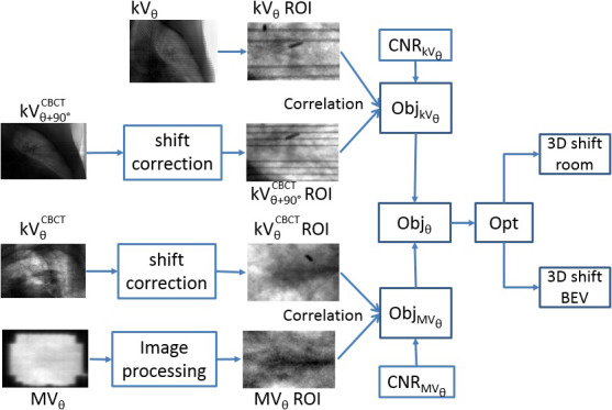
Flowchart of MV/kV imaging‐based 3D localization. [Color figure can be viewed at wileyonlinelibrary.com]
2.B.3. Cross‐validating MV/KV and Calypso
Two patients were included in this retrospective study to cross‐validate the motion traces derived from MV/kV imaging and Calypso system. The first patient has a tumor of 4.9 cc, located in the middle lobe; the second patient has a tumor of 159.4 cc, located in the lower lobe near the diaphragm. Each motion trace was sampled by different clocks (computers) between the two acquisition methods. Synchronization between the two was performed by correlating the first beam hold in the trajectory log to the Calypso timestamp when the target exits the gating window, taking into consideration the reported Calypso beam‐off latency. To evaluate the 3D localization accuracy between the two systems, we calculated the RMSE along the SI, AP, and LAT directions, as well as the 3D displacement vector. We compared the accuracy between the transponder‐based and markerless soft‐tissue tracking.
3. Results
The markerless tracking result of the phantom study is shown in Fig. 3. When the MV (blue in panel a) or kV (cyan in panel a) projections were analyzed independently to derive the SI position of the tumor, the RMSE with respect to the actual couch position (red) were 4.1 and 1.3 mm, respectively. The results from the kV imaging were more robust than for MV, which can be attributed to its relatively higher image contrast (panel b). In the gantry range between 115° and 175°, however, where there was larger attenuation in the laterally acquired kV images, MV imaging did provide more accurate registration results, improvement up to 4.5 mm in absolute amplitude compared to using kV alone. When the SI trace was calculated by an objective function weighting the CNR of the MV/kV images (blue in panel 3), tracking accuracy was improved and the RMSE was reduced to 1.2 mm. Most of the improvement lies in the gantry interval of 115°–175° which accounts for 30% of the studied arc: the RMSE of simultaneous MV/kV tracking in this subarc is 0.7 mm, significantly lower than 2.0 mm of kV alone. Furthermore, simultaneous tracking performs more reliably than kV‐alone, evidenced by the reduction of 14% in instances where tracking error exceeds 2 mm in the SI direction; this would lead to more accurate and robust interventions. Therefore, performance of MV/kV‐based tracking is superior to that of MV or kV alone. Noticeable discrepancies up to 16 mm occurred around the gantry angles of 175°–180°, where the tumor significantly overlaps with the central structure and CNR in both MV and kV images was consistently low. Representative MV/kV projections and their corresponding CBCT projections are illustrated in Fig. 4. Although no motion was programmed along the LAT and AP direction in the phantom study, the RMSE along the LAT and AP direction (magenta and green in panel c) were 1.2 and 1.4 mm, respectively. Most of these errors were a result of the low image contrast leading to large registration uncertainties. The overall 3D RMSE was 2 mm. In 89% of the images, the accuracy (RMSE) of the 3D localization was better than 3 mm. In the MV‐BEV, which is more important in a dosimetric sense, the discrepancies in the SI‐MV‐BEV and LAT‐MV‐BEV direction are 1.2 and 1.3 mm, respectively.
Figure 3.
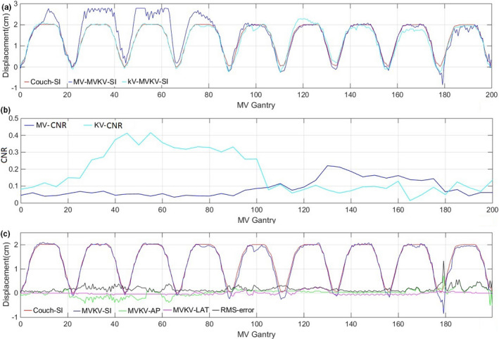
(a) Tracking tumor in the SI direction with MV/kV pairs (red) is superior to MV (blue) or kV (cyan) alone. (b) CNR of MV (blue) and kV (cyan) images with respect to gantry rotations. (c) 3D tracking results compared with actual couch motion. [Color figure can be viewed at wileyonlinelibrary.com]
Figure 4.
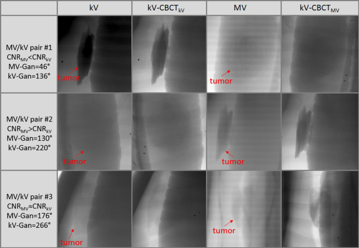
Comparisons of kV image, corresponding CBCT projection (kV‐CBCT kV), MV image and corresponding CBCT projection (kV‐CBCTMV ), at three different gantry angles highlight the compliment of MV and kV images in a phantom study. [Color figure can be viewed at wileyonlinelibrary.com]
For the MV/kV imaging of the two patients treated with VMAT and gated with Calypso, on average, in 25% of the measurements the transponders and the GTV were simultaneously visible from MV/kV‐BEV, enabling direct comparisons between marker‐ and markerless tracking. However, the radiofrequency signal from the Calypso system introduces periodic interference in the MV images. In general, only one or two frames of MV images acquired within a specific gating window were clear and usable for the purpose of registration. The motion trace of a typical setup CBCT is shown in Fig. 5, which is reconstructed by registering the CBCT projections to the corresponding planning CT templates. The relative discrepancy of this trace to Calypso signal is within 1 mm. Using the Calypso signal as ground truth, the overall 3D localization accuracy of marker‐ and markerless tracking is shown in Table 1. Representative MV/kV images and their corresponding CBCT projections from the patient study are illustrated in Fig. 6. Providing the MV‐kV registration with the CNR‐guidance is the key for a successful 3D markerless localization, improving the 3D registration accuracy to 2.0 ± 0.9 mm, compared to 5.7 ± 3.2 mm when running the MV and kV registration without CNR‐guidance (removing the CNR‐based weighting in the objective function). In fact, 71% of the 3D localization instances benefited from the CNR‐guidance because it helps to (a) unambiguously determine the SI shift which is seen in common in the MV‐ and kV‐BEV, and (b) avoid traps of local minima which can cause loss of registration when image contrast, especially in the MV image, is low. In the MV‐BEV, the discrepancies in the SI‐MV‐BEV and LAT‐MV‐BEV direction are −0.2 ± 0.6 mm, and 0.5 ± 0.9 mm, respectively. When image features such as the boundary of GTV are visible, markerless tracking has similar accuracy as transponder tracking, with a 3D accuracy of 2 mm, similar to the phantom study. However, when more than 50% of the tumor is blocked by the MLC, the cross‐correlation between the MV‐ROI and the corresponding kV‐CBCT‐ROI can no longer serve as a reliable objective function. All registration under these scenarios failed the criterion of figure of merit,26 and could not yield 3D localization result. For this real‐time tracking system, the latency of the MV/kV image acquisition system and image registration are both 100 ms.
Figure 5.
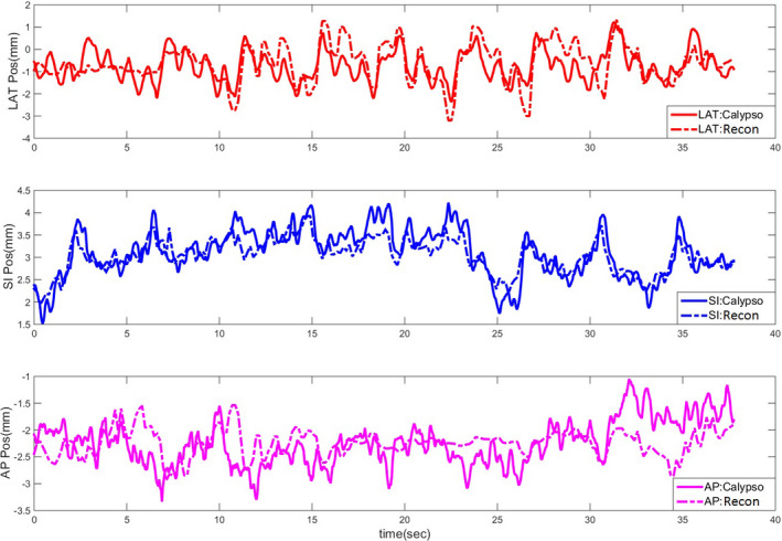
A motion trace of the daily CBCT scan reconstructed via image registration to the planning CT at the phase of end expiration. [Color figure can be viewed at wileyonlinelibrary.com]
Table 1.
Accuracy of tracking compared with Calypso
| Localization target | SI (mm) | AP (mm) | LAT (mm) | 3D displacement (mm) |
|---|---|---|---|---|
| Transponders | 0.1 ± 1.4 | −0.1 ± 1.6 | −0.4 ± 1.9 | 2.3 ± 1.7 |
| Markerless | −0.2 ± 0.6 | 0.2 ± 1.0 | 1.2 ± 1.5 | 2.0 ± 0.9 |
Figure 6.
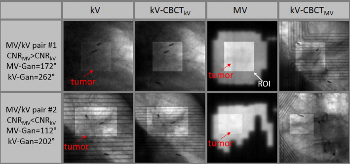
MV and kV images provide robust matching at different gantry angles. Although visibility of tumor is low in some kV (upper panel) or MV (lower panel) images, guidance from the other image in the image pair enables valid 3D localization. Note that the artifact caused by the Calypso panel inside the kV and CBCT projections would not exist in a pure MV/kV tracking study. [Color figure can be viewed at wileyonlinelibrary.com]
4. Discussion
Our findings in both phantom and patient studies illustrate the potential and challenges of markerless tracking during treatment of lung tumors. Applying the new clinical approach of 3D localization via registering the composite MV/kV to the daily CBCT projections is superior to either MV or kV imaging alone, in terms of both localization accuracy and robustness. Because the IRB‐approved protocol was primarily designed to test the feasibility of gating the treatment with the Calypso signal, the useful MV images acquired during beam‐on were all within the gating window of roughly 3–5 mm in all directions around end expiration. As a result, our algorithm was not challenged in the patient study as in the phantom study to perform registration over the full cycle of respiration. The 3D localization accuracy of 2 mm demonstrated by our algorithm is reasonable for evaluating whether the tumor is within the gate, and would not cause significant dosimetric errors in tumor coverage. Therefore, this noninvasive, real‐time, and markerless technique has the potential to be incorporated into clinical operations to aid the practice of lung radiotherapy including strategies such as deep inspiration breath‐hold (DIBH) or gated treatment. We envision a possible clinical workflow beginning with the simulation 4DCT scan. By viewing digitally reconstructed radiographs (DRR) along the path of treatment arcs, one can screen potential candidates for markerless tracking using criteria of CNR and tumor visibility. At the commissioning or initial stage of implementing the markerless tracking technique, or for selected patients for quality assurance, a 3D print of the tumor could be fabricated, and a patient‐specific study performed to ensure the designed VMAT plan is compatible with markerless tracking, and investigate what level of tracking accuracy can be achieved under various respiratory scenarios using motion traces of prior patients. By reconstructing dose distributions from a phantom or computer simulation study, one can also estimate the dosimetric impact, and determine action thresholds such as an appropriate gating window to guide treatment delivery. Furthermore, we can also investigate the possibility to reduce the frequency of kV imaging and thereafter imaging dose associated with the surveillance procedure. With this information, we would be well prepared to better serve lung patients with an optimized workflow.
The cornerstone of our proposed MV/kV markerless tracking platform is the establishment of a reliable reference between the intrafractional images and the daily setup CBCT. One significant concern in this study is the accuracy with which all the projections are registered to a specific reference phase/position because most of the CBCTs are currently acquired during free breathing in our clinic. However, a gated or breath‐hold CBCT that has the breathing phase and amplitude information embedded inside the projection data would facilitate the calculation of the motion trace, and improve the reliability and accuracy of such registration especially in the scenario where soft tissues (tumor or surrounding structures) rather than transponders are used for registration template. Such technical capability is available in the latest version of the TrueBeam control software (v2.7), and ready to be tested in the clinical setting. As an alternative, automatic sorting of the CBCT projections based on Fourier transform27 can be applied to facilitate the registration. Another source of error lies in the low image quality of the MV images. A combination of mitigation steps including carefully calibrating the EPID detector, reducing the effect of scatter via a high pass filter, systematically correcting the inhomogeneity caused by the beam intensity profile, imposing optimization constraints to enable larger beam apertures, and inserting special imaging control points in the VMAT delivery to increase the field‐of‐view and hence tumor visibility in the MV imaging, will be investigated in future.
5. Conclusion
A combined gantry‐mounted MV/kV imaging system can yield real‐time 3D localization of lung tumor, with comparable accuracy to the Calypso system when tumor features are detectable. Careful design of a registration algorithm and a VMAT plan that maximizes tumor visibility are key elements for a successful MV/KV localization strategy.
Acknowledgment
Memorial Sloan‐Kettering Cancer Center has a research agreement with Varian Medical Systems. This research was partially supported by the MSK Cancer Center Support Grant/Core Grant (P30 CA008748).
References
- 1. Keall PJ, Todor AD, Vedam SS, et al. On the use of EPID‐based implanted marker tracking for 4D radiotherapy. Med Phys. 2004;31:3492–3499. [DOI] [PubMed] [Google Scholar]
- 2. Wiersma RD, Mao W, Xing L. Combined kV and MV imaging for real‐time tracking of implanted fiducial markers. Med Phys. 2008;35:1191–1198. [DOI] [PMC free article] [PubMed] [Google Scholar]
- 3. Mao W, Hsu A, Riaz N, et al. Image‐guided radiotherapy in near real time with intensity‐modulated radiotherapy megavoltage treatment beam imaging. Int J Radiat Oncol Biol Phys. 2009;75:603–610. [DOI] [PubMed] [Google Scholar]
- 4. Cho B, Poulsen PR, Sawant A, et al. Real‐time target position estimation using stereoscopic kilovoltage/megavoltage imaging and external respiratory monitoring for dynamic multileaf collimator tracking. Int J Radiat Oncol Biol Phys. 2011;79:269–278. [DOI] [PMC free article] [PubMed] [Google Scholar]
- 5. Yan H, Li H, Liu Z, et al. Hybrid MV‐kV 3D respiratory motion tracking during radiation therapy with low imaging dose. Phys Med Biol. 2012;57:8455–8469. [DOI] [PubMed] [Google Scholar]
- 6. Lin WY, Lin SF, Yang SC, et al. Real‐time automatic fiducial marker tracking in low contrast cine‐MV images. Med Phys. 2013;40:011715. [DOI] [PubMed] [Google Scholar]
- 7. Azcona JD, Li R, Mok E, et al. Development and clinical evaluation of automatic fiducial detection for tumor tracking in cine megavoltage images during volumetric modulated arc therapy. Med Phys. 2013;40:031708. [DOI] [PMC free article] [PubMed] [Google Scholar]
- 8. Yip SSF, Rottmann J, Chen H, et al. Technical Note: combination of multiple EPID imager layers improves image quality and tracking performance of low contrast‐to‐noise objects. Med Phys. 2017;44:4847–4853. [DOI] [PubMed] [Google Scholar]
- 9. Trumm CG, Häussler SM, Muacevic A, et al. CT fluoroscopy‐guided percutaneous fiducial marker placement for CyberKnife stereotactic radiosurgery: technical results and complications in 222 consecutive procedures. J Vasc Interv Radiol. 2014;25:760–768. [DOI] [PubMed] [Google Scholar]
- 10. Cho B, Poulsen PKP. Real‐time tumor tracking using sequential kV imaging combined with respiratory monitoring: a general framework applicable to commonly used IGRT systems. Phys Med Biol. 2010;55:3299–3316. [DOI] [PMC free article] [PubMed] [Google Scholar]
- 11. Li R, Fahimian BXL. A Bayesian approach to real‐time 3D tumor localization via monoscopic x‐ray imaging during treatment delivery. Med Phys. 2011;38:4205–4214. [DOI] [PMC free article] [PubMed] [Google Scholar]
- 12. Cho B, Poulsen P, Ruan D, et al. Experimental investigation of a general real‐time 3D target localization method using sequential kV imaging combined with respiratory monitoring. Phys Med Biol. 2012;57:7395–7407. [DOI] [PMC free article] [PubMed] [Google Scholar]
- 13. Rottmann J, Aristophanous M, Chen A, et al. A multi‐region algorithm for markerless beam's‐eye view lung tumor tracking. Phys Med Biol. 2010;55:5585–5598. [DOI] [PubMed] [Google Scholar]
- 14. Rottmann J, Keall P, Berbeco R. Markerless EPID image guided dynamic multi‐leaf collimator tracking for lung tumors. Phys Med Biol. 2013;58:4195–4204. [DOI] [PMC free article] [PubMed] [Google Scholar]
- 15. van de Sörnsen Koste JR, Dahele M, Mostafavi H, et al. Digital tomosynthesis (DTS) for verification of target position in early stage lung cancer patients. Med Phys. 2013;40:011904. [DOI] [PubMed] [Google Scholar]
- 16. Patel R, Panfil J, Campana M, et al. Markerless motion tracking of lung tumors using dual‐energy fluoroscopy. Med Phys. 2015;42:254–262. [DOI] [PubMed] [Google Scholar]
- 17. van SdKJ, Dahele M, Mostafavi H, et al. Markerless tracking of small lung tumors for stereotactic radiotherapy. Med Phys. 2015;42:1640–1652. [DOI] [PubMed] [Google Scholar]
- 18. Yip SS, Rottmann J, Berbeco R. Beam's‐eye‐view imaging during non‐coplanar lung SBRT. Med Phys. 2015;42:6776–6783. [DOI] [PMC free article] [PubMed] [Google Scholar]
- 19. Shieh C‐C, Caillet V, Dunbar M, et al. A Bayesian approach for three‐dimensional markerless tumor tracking using kV imaging during lung radiotherapy. Phys Med Biol. 2017;62:3065. [DOI] [PMC free article] [PubMed] [Google Scholar]
- 20. Richter A, Wilbert J, Baier K, et al. Feasibility study for markerless tracking of lung tumors in stereotactic body radiotherapy. Int J Radiat Oncol Biol Phys. 2010;78:618–627. [DOI] [PubMed] [Google Scholar]
- 21. Hunt M, Sonnick M, Pham H, et al. Simultaneous MV‐kV imaging for intra‐fractional motion management during volume modulated arc therapy delivery. JACMP. 2016;17:473–486. [DOI] [PMC free article] [PubMed] [Google Scholar]
- 22. Hazelaar C, van Eijnatten M, Dahele M, et al. Using 3D printing techniques to create an anthropomorphic thorax phantom for medical imaging purposes. Med Phys. 2018;45:92–100. [DOI] [PubMed] [Google Scholar]
- 23. Deasy JO, Blanco AI, Clark VH. CERR: a computational environment for radiotherapy research. Med Phys. 2003;30:979–985. [DOI] [PubMed] [Google Scholar]
- 24. Lujan AE, Larsen EW, Balter JM, Ten Haken RK. A method for incorporating organ motion due to breathing into 3D dose calculations. Med Phys. 1999;26:715–720. [DOI] [PubMed] [Google Scholar]
- 25. Dzyubak O, Kincaid R, Hertanto A, et al. Evaluation of tumor localization in respiration motion‐corrected cone‐beam CT: prospective study in lung. Med Phys. 2014;41:101918. [DOI] [PMC free article] [PubMed] [Google Scholar]
- 26. Mostafavi H, Sloutsky A, V A. Detection and localization of radiotherapy target by template matching. Conf Proc IEEE Eng Med Biol Soc. 2012;2012:6023–6027. [DOI] [PubMed] [Google Scholar]
- 27. Vergalasova I, Cai J, Yin FF. A novel technique for markerless, self‐sorted 4D‐CBCT: feasibility study. Med Phys. 2012;39:1442–1451. [DOI] [PMC free article] [PubMed] [Google Scholar]


