

Abstract
The cortical processing of illusory contours provides a unique window for exploring the brain mechanisms underlying visual perception. Previous electrophysiological single-cell recordings demonstrate that a subgroup of cells in macaque V1 and V2 signal the presence of illusory contours, whereas recent human brain imaging studies reveal higher-order visual cortices playing a central role in illusory figure processing. It seems that the processing of illusory contours/figures may engage multiple cortical interactions between hierarchically organized processing stages in the ventral visual pathway of primates. However, it is not yet known in which brain areas illusory contours are represented in the same manner as real contours at both the population and single-cell levels. Here, by combining intrinsic optical imaging in anesthetized rhesus macaques with single-cell recordings in awake ones, we found a complete overlap of orientation domains in visual cortical area V4 for processing real and illusory contours. In contrast, the orientation domains mapped in early visual areas V1 and V2 mainly encoded the local physical stimulus features inducing the subjective perception of global illusory contours. Our results indicate that real and illusory contours are encoded equivalently by the same functional domains in V4, suggesting that V4 is a key cortical locus for integration of local features into global contours.
Introduction
How our brains perceive reality versus illusion remains an outstanding question (Gregory, 1972; Macknik and Haglund, 1999; Eagleman, 2001; Eysel, 2003; Jancke et al., 2004). Illusory contours (ICs), such as the Kanizsa triangle and abutting-line gratings, are among the most frequently used illusory figures in studying form perception and object recognition (Kanizsa, 1976; Spillmann and Dresp, 1995; Nieder, 2002; Seghier and Vuilleumier, 2006). Previous electrophysiological studies have reported that ∼20∼40% of cells in macaque V1 and V2 signal the presence of ICs (von der Heydt et al., 1984; Peterhans and von der Heydt, 1989; von der Heydt and Peterhans, 1989; Grosof et al., 1993; Lee and Nguyen, 2001). An earlier optical-imaging study reported that abutting-line ICs activate overlapped orientation domains in V2 in comparison with those activated by luminance gratings, but inverted in V1 (Ramsden et al., 2001). However, a recent study in cat indicates that the overlap or reversal critically depends upon the inducer spatial frequencies (Zhan and Baker, 2008). Meanwhile, some recent human brain-imaging studies have shown robust IC-related activities in higher visual areas such as the lateral occipital complex, supporting the possibility of feedback inputs to lower visual areas in IC processing (Mendola et al., 1999; Murray et al., 2002; Stanley and Rubin, 2003; Montaser-Kouhsari et al., 2007). Despite these evident neural correlates, a key question remains concerning the cortical locus where ICs are equivalently represented as real contours.
Area V4 is an important intermediate stage for form vision along the hierarchy of primate ventral pathway (Desimone and Schein, 1987; Gattass et al., 1988; Felleman and Van Essen, 1991; Schiller and Lee, 1991; Gallant et al., 1993; Merigan, 2000; Ungerleider et al., 2008) and exhibits some cue-invariant coding capability, such as for global contours defined by motion (Sáry et al., 1993; Mysore et al., 2006). Receptive fields of neurons in V4 are on average four to seven times larger than those in V1 and V2 (Desimone and Schein, 1987; Gattass et al., 1988; Pollen et al., 2002; Motter, 2009). This difference enables V4 neurons to pool inputs from multiple neurons in lower-level cortices (Ghose and Maunsell, 1999; Pasupathy and Connor, 2001, 2002; David et al., 2006; Cadieu et al., 2007; Motter, 2009; Rust and Dicarlo, 2010), providing a potential mechanism for integration of local features into global ICs across a large area of the visual field (Fig. 1). However, direct evidence concerning this functional role of V4 is surprisingly lacking. In this study, by combining intrinsic optical imaging in anesthetized macaques with single-cell recordings in awake ones, we discovered that V4 was a crucial cortical locus where ICs were represented in a manner equivalent to real ones at both population and single-cell levels. We also found that the functional domains mapped in V1 and V2 mainly encoded local stimulus features rather than directly represented IC orientations. These results offer new insights into circuit organizations for the integration of local features into global contours in primate early ventral visual pathway.
Figure 1.

A schematic illustration depicting the sizes of RFs of neurons in V1, V2, and V4, relative to straight and curved ICs defined by spatially aligned abutting lines similar to those used in the current study. One hypothesis is that spatially aligned neurons with smaller RFs in V1 and V2 project to IC-selective neurons with larger RFs in V4, therefore generating a more robust response to IC in V4. For illustrative purposes, the RF diameter of V1 and V2 neurons was taken as 1° and that of V4 neuron as 6°.
Materials and Methods
Animal preparation and maintenance for optical imaging.
All experimental procedures for primate research were approved by the Institute of Neuroscience Institutional Animal Care and Use Committee and by the local ethical review committee of the Shanghai Institutes for Biological Sciences. A total of eight adult male rhesus macaques (Macaca mulatta) weighing 3.0∼4.5 kg were prepared and maintained for optical imaging as described previously (Schiessl et al., 2008), except that ketamine hydrochloride (15 mg · kg−1, i.m.) was used instead of Saffan. Craniotomy and durotomy were performed on both sides of the skull over V1, V2, and V4 for dual optical imaging using two stainless steel chambers of 30 mm diameter secured to skull using dental cement. The lunate sulcus (LS) and superior temporal sulcus (STS) were used as cortical landmarks for surgeries. In each experiment, gas-permeable contact lenses were applied to protect the animal's corneas and the animal's eyes were refracted to focus on the CRT monitor; additional correcting lenses were used where necessary.
Electrophysiological recordings in awake monkeys and data analysis.
All procedures for awake monkey experiments were conducted in compliance with the National Institutes of Health Guide for the Care and Use of Laboratory Animals, and were approved by the Institutional Animal Care and Use Committee of Beijing Normal University. The procedure for animal preparation was similar to that in previous studies (Li et al., 2008), except that electrophysiological recordings were conducted using multielectrode array (Utah Array; Blackrock Microsystems) chronically implanted in V4 of two male macaques within a comparable region to that used in the imaging experiments. The array contained 6 × 8 microelectrodes. Each individual electrode was 0.5 mm long and spaced 0.4 mm apart. Only data from those electrodes that were able to pick up well isolated single units were included in the analyses.
For each well isolated single unit, we estimated its preferred orientations in response to both bar and IC stimuli by fitting with Gaussians. Only when the preferred orientations for the bar and IC differed by <15° did we regard the unit as having the same orientation preference for the two stimuli.
Visual stimuli.
For optical imaging experiments, a gamma-corrected CRT monitor (Sony Trinitron Multiscan G520, 1280 × 960 pixels, 100 Hz) was placed 57 cm in front of the animal eyes. Visual stimuli were computer-generated using custom software based on Psychtoolbox-3 (Brainard, 1997; Pelli, 1997), presented binocularly. Sinusoidal luminance gratings (LGs) of four or eight orientations with a spatial frequency (SF) of 1.0∼1.5 cycles · degree−1 (cpd), temporal frequency (TF) of 5.0∼6.0 cycles · second−1 (cps), and contrast of 80∼90% were used. For the optical recordings performed in V4 alone, the SF of LG stimuli ranged between 0.5 and 1.0 cpd. The abutting-line IC stimuli with an inducer SF of 1.5 cpd (interinducer distance: 0.67°) and IC SF of 0.25 cpd (intercontour distance: 2.0°) were used as standard IC stimuli except where otherwise stated. Note that for IC stimuli, the distance between adjacent contours was treated as half a cycle. We also tested IC stimuli defined by a range of inducer SFs (0.6, 0.75, 1.0, 1.2, 1.5, 4.0 cpd). For the IC stimuli with the lowest inducer SF (0.6 cpd), the interinducer distance was 1.67° and IC SF was 0.15 cpd (intercontour distance: 3.33°); for the IC stimuli with the highest inducer SF (4.0 cpd), the interinducer distance was 0.25° and the IC SF was 0.5 cpd (intercontour distance: 1.0°). For IC stimuli with other inducer SF, the corresponding IC SF was set at approximately five to six times that of inducers to produce vivid IC perception. The width of inducer lines was 0.2° for the mid- to low-inducer–SF IC stimuli and 0.03° for highest inducer–SF IC stimuli (4.0 cpd). In all cases, the ICs drifted back and forth along the inducer orientations at a TF of 1.0 cps. The luminance of inducers was ∼0.4 cd · m−2, and that of background was ∼40 cd · m−2.
For electrophysiological experiments in awake monkeys, the visual stimuli were generated by a visual stimulus generator (ViSaGe; Cambridge Research Systems) and were presented binocularly on a gamma-corrected CRT monitor (Iiyama Vision Master Pro 514, 21 inches, 1024 × 768 pixels, 100 Hz) at a viewing distance of 100 cm. A single bar (0.2° wide) or a single IC made of abutting lines (0.04° wide) was used, which drifted back and forth along an axis orthogonal to the contour orientation at a speed of 4.0° · s−1 and with a travel distance of 3.0°. The stimuli were centered in the receptive field (RF) of the recorded neuron, and were truncated by an invisible circular window surrounding the RF. The other settings were identical to those in the imaging experiments.
Optical imaging and data analysis.
All equipment and recording procedures in our custom-built optical imaging system were similar to those described previously (Schiessl et al., 2008), except for modified dual imaging setup and software. Briefly, we used two DALSA Pantera 1M60 CCD cameras (Teledyne DALSA), each combined with a telecentric 55 mm f2.8 video lens (Computar; CBC) for dual recording from two chambers. The visual responses were recorded at 16 video frames per second for a period of 8 s, including 1 s before stimulus onset under 630 ± 10 nm red light illumination. The interstimulus interval was 13 s. For LG stimuli, data were typically averaged over 32 or 64 trials, while for IC stimuli the data were obtained from at least 64 trials and often as many as to 256 trials. The boundary between V1 and V2 was defined using either retinotopic space mapping (Blasdel and Campbell, 2001) or ocular dominance mapping, which produced stripe-like compartments perpendicular to the border between V1 and V2 (Blasdel and Salama, 1986). The cortical locus (prelunate gyrus) located between LS and STS and 35 mm lateral from the midline was selected as a representative area of V4 in macaques for both optical imaging and single-cell recordings (Shipp and Zeki, 1985; Desimone and Schein, 1987; Gattass et al., 1988; Schiller and Lee, 1991; Gallant et al., 1993; Nakamura et al., 1993; De Weerd et al., 1996; Merigan, 1996; Ghose and Ts'o, 1997; Tanigawa et al., 2010).
For each trial, video frames taken in each second were averaged together, and then subtracted and divided by a blank frame (the averaged response for the 1 s interval before the stimulus onset) to generate a single-condition map of reflectance change (ΔR/R). A differential orientation map was created by pixel-by-pixel subtraction of the single-condition maps activated by a stimulus pair with orthogonal orientations (e.g., 0° −90°). Orientation preference maps were constructed using classical vector summation algorithm (Blasdel, 1992). A variability map was obtained to find pixels with large cross-trial variability (e.g., blood vessels and other noisy regions), and a mask was generated based on an empirically chosen threshold (Zhan and Baker, 2008). Pixels within the mask were never used in quantitative analysis. The images were then high-pass filtered (1.1∼1.2 mm in diameter) and smoothed (106∼306 μm in diameter) by circular averaging filters to suppress low- and high-frequency noise while avoiding signal distortion. To quantify the response amplitude, the absolute ΔR/R values in each responsive patch in a differential map (including patches preferring the first and the second condition) were averaged, and this averaged intensity was taken as the response amplitude. A response profile analysis was performed to extract the orientation specificity encoded in a differential map (Basole et al., 2003; Zhan and Baker, 2008). In brief, the area to be analyzed was divided into 12 equally spaced orientation bins (from 0° to 180° with 15° step), according to the orientation preference map derived from LG stimulation. Each orientation bin consisted of the cortical locations tuned to its orientation. To calculate the response profile, the ΔR/R values within each of these orientation bins were averaged to produce a measure of response strength for that particular orientation. The response profiles were normalized to allow for a direct comparison between the activity patterns elicited by LGs and ICs. We measured the Spearman correlation coefficient between two response profiles using a bootstrapping method with at least 1000 iterations and obtained the 95% confidence interval of the correlation coefficient. A sinusoid was also fitted to each response profile and the angular distance between the two fitted sinusoids was used as an index of similarity between the two curves. We also used two other methods, vector summation and von Mises circular function fitting, to characterize the orientation selectivity of response profiles (Swindale, 1998), and in all cases in the current study, the two methods yielded similar results as those from sinusoidal fitting. Furthermore, we adopted the spatial correlation coefficient (SCC) metric between two differential maps as an index of similarity (for details, see Ramsden et al., 2001). The value of SCC ranged between −1 and 1, with 1 indicating two identical maps and −1 indicating two identical but inverted maps.
Results
Simultaneous imaging of V1, V2, and V4 in response to the same LG and IC stimuli
Previous single-cell recordings in macaques have shown that IC-related activities are consistently observed in a subpopulation of V1 and V2 neurons (von der Heydt et al., 1984; Peterhans and von der Heydt, 1989; von der Heydt and Peterhans, 1989; Grosof et al., 1993; Heider et al., 2000; Lee and Nguyen, 2001), with 15.5% (16/103) of V2 neurons devoted to IC encoding without signaling the orientation of the inducer lines (von der Heydt and Peterhans, 1989). To make a direct comparison between V4 and earlier visual areas in response to the same LG and IC stimuli, we performed simultaneous optical imaging across V1, V2, and V4 in the same hemisphere (Fig. 2A). This approach allowed for a direct comparison of neural responses to the same visual stimuli across the three hierarchically organized visual cortical areas.
Figure 2.
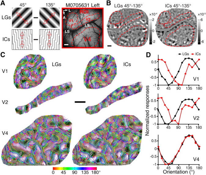
Simultaneous recording from V1, V2, and V4 in response to the same LG and IC stimuli. A, A picture of the surface vasculature overlying the imaged region of V1, V2, and V4 with the ROI from the first monkey along with diagrams of the visual stimuli used to map cortical responses. The red arrows indicate the drift directions of the stimuli. Red outlines delineate the areas of V1, V2, and V4 that were analyzed in B–D. B, Differential orientation maps recorded simultaneously across the three different visual areas. C, The three representative regions (of V1, V2, and V4) that were activated by LGs and ICs in B superimposed with iso-orientation contours. D, Results of response profile analysis from the representative areas in V1, V2, and V4. Profiles produced by LGs and ICs were almost identical in V4, while those in V1 and V2 showed clear orientation preference shifts for IC stimuli. A, Anterior; L, lateral; M0705631, macaque number. Scale bars, 1 mm.
Within a cortical region of interest (ROI), differential orientation maps were generated by subtracting the optical signals elicited by a pair of contour stimuli with orthogonal orientations. Consistent with previous reports (Blasdel and Salama, 1986; Grinvald et al., 1986; Ts'o et al., 1990; Ghose and Ts'o, 1997; Tanigawa et al., 2010), drifting full-field sinusoidal LGs generated differential orientation maps (for example 45° and 135°; Fig. 2A,B) that encoded orientation selectivity within V1, V2, and V4 of the macaque. Strikingly, ICs oriented at 45° and 135° elicited clear responses in all three areas, with the response magnitudes elicited by ICs being weaker than those produced by LGs (Fig. 2B, right). Note that ICs had identical orientations to the LGs, but were defined by 90° inducer lines at SF of 1.5 cpd (Fig. 2A). To quantify the spatial relationship between the corresponding maps generated by LGs and ICs, we performed response profile analysis using previously described methods (Basole et al., 2003; Zhan and Baker, 2008). Iso-orientation contours, derived from orientation preference maps generated by LGs of four or eight orientations, were superimposed onto the ROIs of differential maps of LGs and ICs to evaluate the response strength of multiple cortical orientation domains (see Materials and Methods, above; Fig. 2C). The magnitudes of signals within regions sharing a common preferred orientation were averaged to give a measurement of response strength for that orientation. Using the response profile analysis we found that, as expected, the response profiles for LGs matched precisely the LG orientations of 45° and 135° across all three processing stages (Fig. 2C,D). However, a comparison of LG- and IC-activated orientation domains in V1, V2, and V4 yielded rather distinct results: while we observed precisely overlapped response profiles in V4 for LGs and ICs (95% confidence interval of correlation coefficient: 0.86–1.00; shift of the profile peak: 0.39°), the response profiles in V1 and V2 were only partially overlapped, both showing a remarkable shift in their orientation preferences (95% confidence interval of correlation coefficient for V1: −0.49–0.52 and fitted shift: 43.35°; for V2: −0.52–0.57 and fitted shift: 36.96°; Fig. 2C,D). The orientation domains elicited by LGs and ICs oriented at 0° and 90° in a different ROI of the same hemisphere produced similar findings. These simultaneous optical imaging of V1, V2, and V4 to the same real and illusory contour stimuli clearly demonstrated that it was V4, rather than V1 and V2, where both real and illusory contours were represented equivalently within the same orientation domains.
We further compared V4 responses to IC stimuli with identical orientation of illusory contours but orthogonal inducer lines. As illustrated in Figure 3A, the 0° and 90° pair of IC stimuli was generated by inducer lines oriented at either 45° or 135°. Similarly, the 45° and 135° IC pair was created by either 0° or 90° inducers. Differential orientation maps in V4 were compared in response to these stimuli (Fig. 3B,C). The response profile analysis showed that the response profiles were closely matched with each other for LGs and ICs, independently of the orientations of the inducers in the IC stimuli (Fig. 3D). In particular, for LG and IC response profiles generated by the 0°-90° contour stimuli, the 95% confidence interval of the correlation coefficient was between 0.56 and 0.98 for ICs defined by 45° inducers, and between 0.40 and 1.00 for 135° inducers; the orientation preference shift was 16.52° and 7.75°, respectively. Similarly, for the LG and IC response profiles generated by the 45°-135° contour stimuli, the 95% confidence interval of the correlation coefficient was between 0.94 and 1.00 for ICs defined by 90° inducers, and between 0.95 and 1.00 for 0° inducers; the orientation preference shift was 1.00° and 0.08°, respectively. These results indicate that clear orientation-selective domains are present in V4 for global IC processing that is independent of inducer orientations and is equated with real contour processing. This matching pattern of orientation domains in response to LGs and ICs was consistently observed in V4 of all five macaques tested (for further examples, see Fig. 4). In contrast with V4, the shifted response profiles for LGs and ICs in both V1 and V2 were also repeatedly observed in all experiments across the six macaques tested (Fig. 5).
Figure 3.
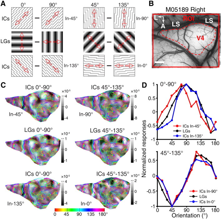
Insensitivity of V4 to manipulations of inducer orientation. A, Diagrams of the LGs and ICs stimuli used. Two variants of each IC–stimulus pair were generated with identical orientation of ICs but orthogonal inducers. In the 0°-90° pair, inducer (In) lines were oriented at 45° (top) and 135° (bottom). For the 45°-135° pair, inducer lines were oriented at 90° (top) or 0° (bottom). Red arrows indicate the drift directions of the stimuli. B, A picture of the imaged ROI obtained from a second monkey with the area of V4 analyzed outlined by red dashed line. C, Differential orientation maps obtained from the outlined region of V4 derived from LG and IC stimuli respectively, with iso-orientation contours superimposed. D, Normalized orientation response profiles for LGs and ICs. Top, Response profiles generated by the 0°-90° orientation pair for the LGs and ICs. Bottom, Response profiles generated by the 45°-135° orientation pair for the LGs and ICs. A, Anterior; L, lateral; M05189, macaque number. Scale bar, 1 mm.
Figure 4.

Further example for the equivalent representation of real and illusory contours in V4. A, A picture of the surface vasculature overlying the cortex around V4 with the ROI from the third monkey along with diagrams of the visual stimuli used to map cortical responses. The area delimited by red dashed line was used for detailed analyses in B–D. Note that the LS was hidden behind the skull in the upper right corner. B, Differential orientation maps derived from the representative area of V4 for LGs and ICs stimuli. C, The representative area of V4 superimposed with iso-orientation contours that were derived from the orientation preference map generated using LGs. D, Normalized response profiles for LGs and ICs. The 95% confidence interval of the correlation coefficient between LGs and ICs was from 0.85 to 1.00, and the fitted orientation preference shift between these two curves was 4.35°. A, Anterior; L, lateral; M2, macaque number. Scale bars, 1 mm.
Figure 5.
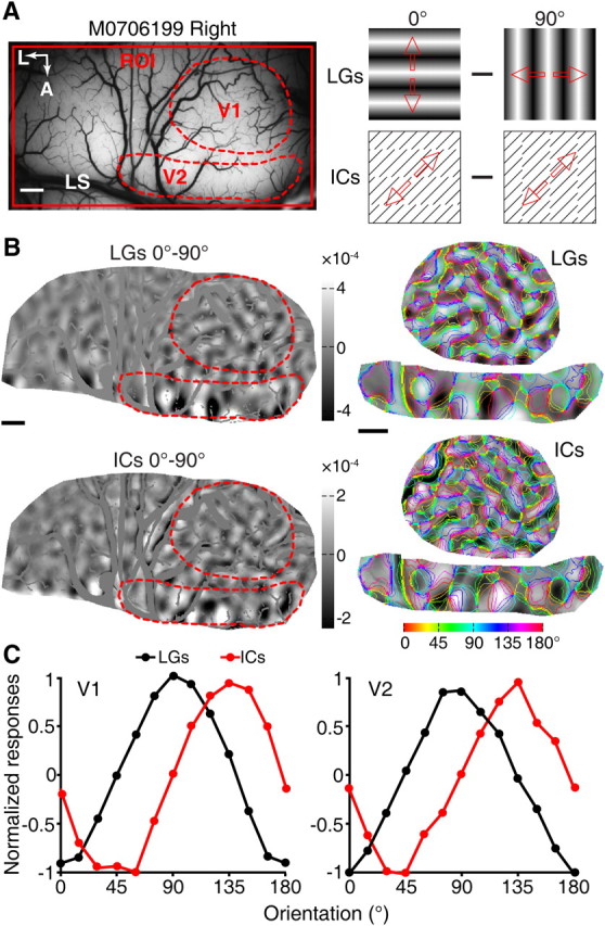
Functional domains in V1 and V2 activated by LG and IC stimuli. A, A picture of the surface vasculature from the imaged region of the fourth monkey. Responses of the regions of V1 and V2, indicated by the broken red lines, were further analyzed in B and C. Responses from V1 and V2 were recorded simultaneously using 0° and 90° stimuli of LGs and ICs, as indicated. B, Differential orientation maps generated from the cortical responses to the 0° and 90° pairs of LG and IC stimuli demonstrate a partial overlap of the two maps. Representative areas in V1 and V2, indicated by the red dashed line, were superimposed with iso-orientation contours derived from LG stimuli and response profile analysis performed. C, Results of response profile analysis from V1 and V2. The orientation preferences for the LG activated domains were 0° and 90° in both V1 and V2, matching the orientations of LG stimuli as expected. The IC stimuli, however, exhibited a clear shift of population responses (41.54° for V1 and 42.0° for V2, calculated from sinusoidal fitting). A, Anterior; L, lateral; M0706199, macaque number. Scale bars, 1 mm.
We also tested a range of inducer SFs, either higher or lower than 1.5 cpd with different interinducer spacing (for details, see Materials and Methods, above), but IC stimuli with an inducer SF of 1.5 cpd generally gave the strongest responses. No discernible responses in V1 or V2 were elicited by IC stimuli made of low-SF inducer lines at 0.6 cpd. However, when tested with ICs defined by high-SF inducers of 4.0 cpd, an SF higher than the mean optimal SF of V1 and V2 neurons (Foster et al., 1985; Levitt et al., 1994), we found that the functional domains recorded simultaneously in V1 and V2 were both inverted with respect to those activated by LGs (for a representative example, see Fig. 6). This observation of inverted orientation domains confirmed the antecedent IC study in macaque V1 using IC stimuli with the same high-SF inducers at 4.0 cpd, but did not agree with the claim of overlapped orientation domains in V2 for LGs and ICs from the same study (Ramsden et al., 2001). We also tested this high SF of inducers in V4, but no reliable IC responses were observed, presumably due to the weak perceptual saliency of ICs caused by higher inducer SF (Soriano et al., 1996; Montaser-Kouhsari et al., 2007). It is important to note that the orientation domains activated by IC stimuli in V1 and V2 did not match the global orientations of ICs at all, indicating that they did not encode the orientations of ICs. Together, the results from simultaneous imaging across three different visual stages suggest that the cortical mechanisms for processing real and illusory contours in V4 are fundamentally different from those in V1 and V2, with V4 being a key cortical locus where neurons are organized into functional modules to encode the global orientations, no matter whether they are real or subjective.
Figure 6.

Inverted orientation maps between LG and high-SF IC stimuli in V1 and V2 of a representative monkey. A, A picture of the surface vasculature of the ROI from the fifth monkey. The areas of V1 and V2 whose responses were subsequently analyzed are indicated by the red broken lines along with diagrams of the visual stimuli used. B, Differential orientation maps derived from LGs and ICs stimuli, along with the representative areas of V1 and V2 superimposed with iso-orientation contours. C, Normalized response profiles for LGs and ICs in V1 and V2. These inverted profile curves revealed that LG and high-SF IC stimuli activated orthogonal functional domains in V1 and V2 in an apparently similar manner. A, Anterior; L, lateral; M733, macaque number. Scale bars, 1 mm.
Single-cell recordings of area V4 in response to IC stimuli
Our series of imaging experiments targeted the functional organization of orientation domains and consistently showed that LG- and IC-activated functional domains in V4 precisely overlapped. To validate this important finding at the neuronal level, and also to compare response properties of single V4 neurons with previous well documented properties of V1 and V2 neurons in response to real and illusory contour stimuli, we performed single-cell recordings with microelectrode arrays implanted in the superficial layers of V4 in two awake macaques. The monkeys performed a simple fixation task during V4 recordings, and the same stimulus paradigm was used as in the previous V1 and V2 studies (von der Heydt and Peterhans, 1989). Using an oriented moving bar as the real contour stimulus and a moving IC stimulus defined by abutting lines perpendicular to the IC (see Fig. 8, insets), we measured the orientation selectivity of 36 well isolated single neurons in V4 of two monkeys. The recorded neurons were classified in terms of orientation selectivity for the single bar and the IC stimuli, as previously described in V1 and V2 studies (von der Heydt et al., 1984; von der Heydt and Peterhans, 1989). Among the recorded neurons, three were not selective to the orientation of a single bar stimulus (Fig. 7), even though they showed clear orientation-selective responses to the IC stimulus. The remaining 33 cells were defined as orientation-selective units as they had clear orientation tuning peaks to the bar stimulus. Among these orientation-selective cells, a large proportion (22/33, 66.7%) responded to the IC stimulus at their maximum firing rates when the IC orientation matched the cell's preferred orientation for the single bar (Fig. 8A–E); only these cells were regarded as IC-responsive neurons. Specifically, the percentage of V4 neurons in which optimal responses to ICs occurred at the same orientation as to LGs in the two animals was 55.6% (10/18) and 80.0% (12/15), respectively. The other cells (11/33, 33.3%) were modulated by the orientation of inducer lines in the IC stimuli rather than IC orientation per se, showing optimal responses when the orientation of inducers, but not of the IC, matched the neuron's preferred orientation (Fig. 8F); these cells were taken as non-IC-responsive. It is worth pointing out that, among the IC-responsive neurons, the majority of them (19/22, 86.4%, Fig. 8A–D) were markedly tuned only to the IC orientation without signaling the orientation of inducers (compare the cells in Fig. 8A–D with the one in Fig. 8E). Our electrophysiological results are consistent with our findings using intrinsic optical imaging, indicating that V4 is a key cortical locus where ICs are represented as if they were real at both population and single-cell levels.
Figure 8.
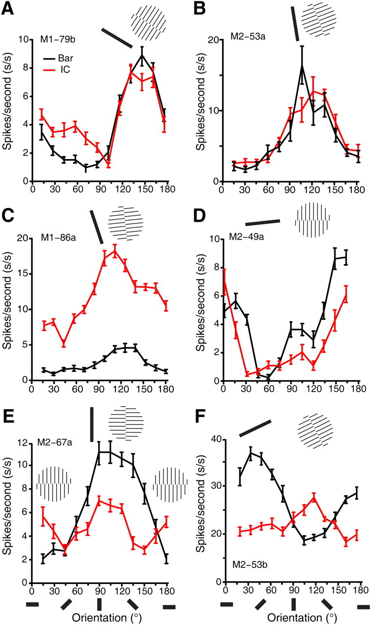
Electrophysiological single-cell recordings from V4 of awake macaques. A–D, Representative orientation tuning curves of neurons in V4 of awake macaques in response to a single luminance-defined moving bar and a single moving illusory contour defined by perpendicular abutting lines. The lengths of the luminance bar and IC were identical. E, An example neuron showing responses to both illusory contour and inducer lines. F, An example neuron responsive to inducer lines only. Error bars in all tuning curves are SEM. The oriented bars below the abscissa represent the orientations of both the bar and IC, and the icons above tuning curves correspond to the actual preferred stimuli for each V4 neuron.
Figure 7.

Three non-orientation-selective V4 neurons recorded from two awake fixating macaques. These neurons demonstrated orientation selectivity to the IC stimuli but not to a single moving bar stimulus. The oriented bars below the abscissa represent the orientations of both the bar and IC.
Statistical comparison across V1, V2, and V4
The differences at the population level in IC representation between V1, V2, and V4 are quantitatively compared in Figure 9. Figure 9A summarizes the response magnitudes for LG and IC stimuli averaged across recorded ROIs of V1, V2, and V4 from all animals studied. As expected, IC stimuli elicited much weaker responses than LG stimuli in all three areas (p < 0.001, two-sample t test). Interestingly, for all types of stimuli used, V2 exhibited the strongest responses. Using the SCC as an index (Ramsden et al., 2001), we calculated the similarity between the differential orientation maps generated by LG and IC stimuli across V1, V2, and V4 (Fig. 9B). An SCC value of 1 indicates that the two maps are pixel-wise identical, while a value of −1 indicates the two maps are identical but inverted. Note that SCC values derived from inverted orientation domains activated by IC stimuli of high-SF inducers were in the range of −0.54 to −1.00 and were not taken into account; these negative SCC values would further reduce the mean SCC in both V1 and V2. As demonstrated in Figure 9B, both the mean (small solid square) and the median (red line) SCC values in V2 were slightly higher than those in V1, but the difference was not statistically significant (p = 0.19, two-sample t test). However, the degree of similarity between IC- and LG-activated maps in V4, as indicated by the significantly larger SCC, was far more pronounced when compared with V1 and V2 (p < 0.002, two-sample t test; Fig. 9B). Using other statistical analysis, such as fitting of orientation response profiles with either sinusoidal function or a simple circular von Mises function (Swindale, 1998), we obtained similar results. For example, the mean angle shift of peak responses between ICs and LGs using sinusoidal fitting is 36.20 ± 12.8° (mean ± SD) in V2, which is slightly smaller than that in V1 (42.76 ± 9.09°) but not significantly (p = 0.44, two sample t test). The mean angle shift in V4 (5.71 ± 6.15°) is significantly smaller than those in both V1 and V2 (p < 0.001, two-sample t test), in accordance with our single-cell recordings in awake macaques showing that two-thirds of V4 neurons (22/33) signaled the orientations of ICs and LGs equivalently. The percentage of IC-responsive neurons that we observed in V4 (22/33, 66.7%) is substantially higher than that previously reported in V1 (1/60, 1.67%) and V2 (45/103, 43.7%) (von der Heydt and Peterhans, 1989). These statistical comparisons across V1, V2, and V4 further corroborate our conclusion that the dedicated functional modules for equivalent representation of the orientation of both LGs and ICs primarily reside in V4, but not in V1 and V2, where neural responses mainly encode for local stimulus features. We hypothesized that this equivalent representation of ICs as if they were real contours in V4 could be accomplished via pooling inputs from multiple V1 and V2 neurons with small receptive fields that are spatially aligned in precise retinotopic coordinates (Fig. 9C) (Hubel and Wiesel, 1968; Ghose and Maunsell, 1999; Riesenhuber and Poggio, 1999; Pasupathy and Connor, 2002; Pollen et al., 2002; David et al., 2006; Cadieu et al., 2007; Motter, 2009; Rust and Dicarlo, 2010; Bushnell et al., 2011). This integration could be implemented by the massive reciprocal connections between V1, V2, and V4 (Shipp and Zeki, 1985; Felleman and Van Essen, 1991; Nakamura et al., 1993; Felleman et al., 1997; Xiao et al., 1999; Ungerleider et al., 2008; Nassi and Callaway, 2009; Ninomiya et al., 2011). Our findings in V1, V2, and V4 offer new insights concerning the cortical loci and their functional organizations for the integration of local features into global contours (Spillmann, 1999; Kourtzi et al., 2003).
Figure 9.
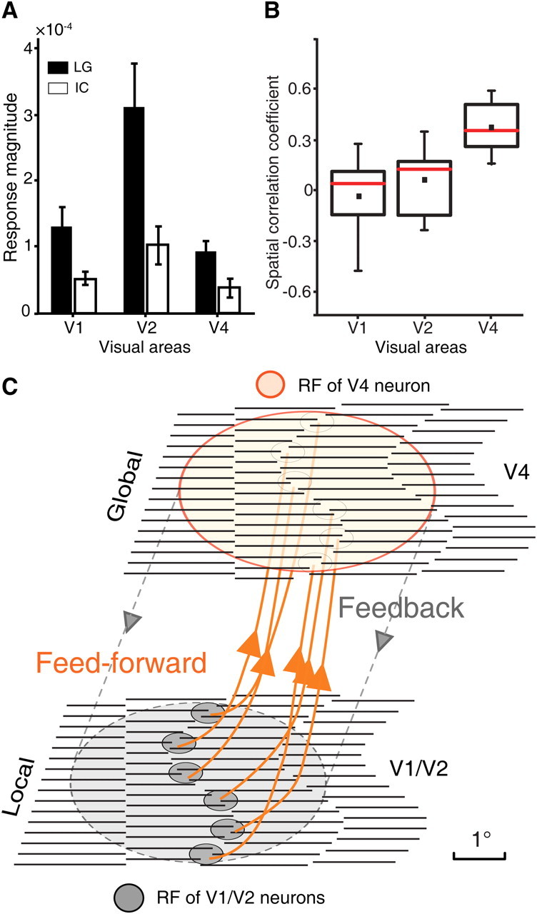
Summary of population responses across V1, V2, and V4. A, A comparison of the response strength of the intrinsic signals elicited by ICs, with the same inducer SF of 1.5 cpd, and LGs across V1, V2, and V4. The response strength was calculated from the relative changes in the reflected light (ΔR/R). Error bars indicate the SEM. The number of differential orientation maps for V1, V2, and V4 evoked by LGs and ICs respectively across seven macaques was 9, 11, and 9, respectively. B, Box plots of spatial correlation coefficients for the three areas studied. The number of pairs of differential orientation maps for V1, V2, and V4 are the same as those in A across the seven macaques studied (the data from Fig. 6 were not included; see text for details). Small solid squares represent mean values while red lines represent median values. C, A highly simplified schematic diagram depicting the possible functional projections and interplay between V1, V2, and V4 for the orientation cue-invariant representation of ICs. Essentially, invariance is increased by pooling V1 and V2 cells tuned to the same abutting lines but at different positions across a large area of the visual field. In this scheme, the majority of V1/V2 cells are activated by local features of the stimulus, while fewer V4 cells are engaged in representing the local features as a consequence of hierarchical pooling. The scale bar was taken as 1° for illustrative purpose only.
Discussion
Subjective or illusory contours, induced by precise geometrical alignment of stimulus features such as abutting lines, have been extensively studied (Grossberg and Mingolla, 1985; Livingstone and Hubel, 1987; Vogels and Orban, 1987; Paradiso et al., 1989; Davis and Driver, 1994; Ramachandran et al., 1994; Ringach and Shapley, 1996; Rubin et al., 1996; Westheimer and Li, 1997; Larsson et al., 1999; Nieder, 2002; Halko et al., 2008; Francis and Wede, 2010; Kalar et al., 2010). More than two decades ago, von der Heydt and colleagues reported in their pioneering work that approximately one-third of V2 cells respond to IC stimuli (von der Heydt et al., 1984; von der Heydt and Peterhans, 1989). Subsequent studies have shown that a small proportion of V1 cells also respond to IC stimuli (Grosof et al., 1993; Lee and Nguyen, 2001) and that IC-related responses in V1 are substantially delayed relative to those in V2, suggesting feedback contributions from V2 to the IC-related responses in V1 (Lee and Nguyen, 2001; Ramsden et al., 2001; Lee and Mumford, 2003). Despite these evident neural correlates, it remains unclear at which processing stages in the primate ventral pathway ICs are represented as if they were real at both population and single-cell levels. Using modern functional magnetic resonance imaging (fMRI), a number of recent studies have demonstrated robust activations to ICs in multiple regions of the human brain including V1 and V2 (for review, see Seghier and Vuilleumier, 2006) and some of these studies have shown distinct activations in downstream areas, including area V4 (Mendola et al., 1999; Murray et al., 2002; Stanley and Rubin, 2003; Montaser-Kouhsari et al., 2007). However, due to the limited spatial resolutions of fMRI techniques, it is very difficult to solve the above long-standing “where” debate (Spillmann and Dresp, 1995; Seghier and Vuilleumier, 2006).
As a crucial area for intermediate form vision, V4 is highly probable to serve as a cortical locus for IC representation. This idea is implicated from an earlier lesion study, which shows that the perception of ICs, but not luminance-defined real contours, is severely impaired after V4 lesion (De Weerd et al., 1996). Using simultaneous optical imaging of intrinsic signals in V1, V2, and V4, we found that the orientation domains encoding both real and illusory contours with the same preference were present only in V4 but not in V1 and V2 (Fig. 2). These findings parallel those from a previous series of studies on motion-defined kinetic contours that shows weak and infrequent tuning in V1/V2 (Marcar et al., 2000) and cue-invariant coding in V4 (Mysore et al., 2006, 2008). These visual cortices in turn give rise to complete shape selectivity in inferior temporal cortex (IT) (Sáry et al., 1993; Kobatake and Tanaka, 1994; Logothetis et al., 1995; Girard et al., 2002). Our results support the hypothesis that the representation of ICs in area V4 is most likely achieved in a feedforward fashion by pooling inputs of spatially aligned V1 and V2 neurons (Fig. 9C), in agreement with recent V4 studies of boundary conformation and invariance (Mysore et al., 2006; Cadieu et al., 2007).
In human fMRI studies, almost all visual areas along the ventral pathway are activated to different levels by IC stimuli, suggesting interactive and concurrent processing of ICs at multiple brain areas (Spillmann and Dresp, 1995; Lee, 2002; Kourtzi et al., 2003; Seghier and Vuilleumier, 2006). Previous electrophysiological studies have consistently shown that a subpopulation of V1 and V2 neurons respond to IC stimuli, suggesting that orientations of ICs are already detected by some V1 and V2 cells. However, as von der Heydt and Peterhans (1989) stated: “… one can hardly expect that neuronal signals at the stage of V2 are already completely invariant against configurations.” Consistent with this speculation, our population data suggest that IC-responsive cells in V1 and V2 could be organized in a “salt and pepper” manner rather than modularized into iso-preference orientation domains. It is worth noting that, in the case of differential maps derived from a pair of ICs with orthogonal orientations, although the overall patterns of the inducers looked similar, the local arrangements of line ends were different. Thus, the population responses in V1 and V2 activated by IC stimuli could simply reflect a difference in combinations of local stimulus features sampled by the small RFs of V1 and V2 neurons. This is consistent with previous findings in ferret and cat primary visual cortex, where shifts of the population responses have been reported for different combinations of local stimulus features (Basole et al., 2003; Baker and Issa, 2005; Mante and Carandini, 2005; Issa et al., 2008).
In the present study, the SF of inducers in IC stimuli was typically 1.5 cpd (interinducer distance of 0.67°), which was well within the optimal range of 1.0–2.8 cpd for both human observers (Soriano et al., 1996; Montaser-Kouhsari et al., 2007) and monkeys (von der Heydt and Peterhans, 1989) to perceive ICs. However, we also tested a range of lower and higher SF of inducers, including 4.0 cpd that was originally used to map IC responses in macaque V1 and V2 in the first report using intrinsic optical imaging (Ramsden et al., 2001). The observation of inverted orientation domains in our simultaneously mapped V1 and V2 at this 4.0 cpd SF confirmed this earlier IC study in macaque V1 with similar ranges of SCC values, but not in V2. This discrepancy may possibly be due to the relatively small size of ROI in V2 reported in the previous study, which could bias the SCC values. Furthermore, in the previous study, only one pair of ICs defined by only one inducer SF of 4.0 cpd was tested and hence no orientation response profiles were generated for detailed quantification. In contrast, based on the orientation response profile analysis across larger ROIs, we tested multiple orientations and SFs of IC stimuli and found shifted or inverted functional domains in both V1 and V2, which were closely associated with the inducer SF. The fact that our V1 and V2 results related to the local spatial features of inducers concurs with the hypothesis that V1 and V2 act as high-resolution filters primarily tuned to local features (Hubel and Wiesel, 1968; De Valois et al., 1982; Adelson and Bergen, 1985; Foster et al., 1985; Levitt et al., 1994; Basole et al., 2003; Hegdé and Felleman, 2003; Lee and Mumford, 2003; Rust et al., 2006; Issa et al., 2008). The shifted population responses in V1 and V2 are not only in agreement with previous IC studies in cat areas 17 and 18, showing greatly shifted orientation domains activated by IC stimuli (Sheth et al., 1996) and their critical dependency on inducer SF (Zhan and Baker, 2008), but also consistent with recent single-cell observations that few V1 and V2 neurons respond to texture-defined boundaries with cue invariance (El-Shamayleh and Movshon, 2011).
Using different techniques with high temporal resolution, growing evidence indicates that IC responses in early visual areas appear tens of milliseconds later than those in higher-tier areas (Lee and Nguyen, 2001; Murray et al., 2002; Halgren et al., 2003). These studies suggest that the IC responses previously found in a subpopulation of V1 and V2 cells could possibly be derived from recurrent cortical networks with feedback from higher-tier areas (De Weerd et al., 1996; Mendola et al., 1999; Lee and Nguyen, 2001; Lee, 2002; Murray et al., 2002; Halgren et al., 2003; Lee and Mumford, 2003; Stanley and Rubin, 2003). Our optical recordings of V1, V2, and V4 were performed in anesthetized macaques, in which attention and other cognitive top-down influences were absent; therefore, the recorded neural activities merely reflected the intrinsic properties of hardwired neural projections between V1, V2, and V4. Together with our single-cell data from V4 of awake macaques, our findings support the hypothesis that a progressive cascade of integration along multiple hierarchical stages of the visual ventral pathway could mediate the representation of ICs and the global contours in general.
Together, our findings at both the population and single-cell levels demonstrate that the equivalent representation of ICs as if they were real contours primarily occurs in V4, where different visual features are integrated across a relatively large area of visual space (Desimone and Schein, 1987; Gattass et al., 1988; Gallant et al., 1993; Burrows and Moore, 2009; Motter, 2009) and where invariant representations of stimulus features critical for intermediate form vision are achieved (Sáry et al., 1993; Riesenhuber and Poggio, 1999; Pasupathy and Connor, 2001, 2002; David et al., 2006; Mysore et al., 2006; Cadieu et al., 2007; Rust and Dicarlo, 2010). Together with earlier observations in V1 and V2 of primates and recent single-cell recordings in IT of awake macaques (Sáry et al., 2007), our findings support the hypothesis that the representation of ICs may be achieved by a progressive integration of local cues through the reciprocal circuits of V1, V2, and V4, with V4 as a key player mediating the feedforward and feedback processing streams.
Footnotes
This work was supported by National “973” Program 2011CBA00405, the Chinese Academy of Sciences (CAS) “Hundred Talents Program” award (to W.W.), and National Natural Science Foundation of China Grant 30970983 (to W.L.). We thank Drs. Mu-ming Poo, Curtis Baker, Niall McLoughlin, Yves Frégnac, and Lothar Spillmann for comments and suggestions on the manuscript; Dr. Robert Desimone for advice on single-cell recordings in V4 of awake macaques; and Drs. Zoltan Toth, Ingo Schiessl, and Niall McLoughlin for their contribution to the construction of our custom-made optical imaging facility.
The authors declare no competing financial interests.
References
- Adelson EH, Bergen JR. Spatiotemporal energy models for the perception of motion. J Opt Soc Am A. 1985;2:284–299. doi: 10.1364/josaa.2.000284. [DOI] [PubMed] [Google Scholar]
- Baker TI, Issa NP. Cortical maps of separable tuning properties predict population responses to complex visual stimuli. J Neurophysiol. 2005;94:775–787. doi: 10.1152/jn.01093.2004. [DOI] [PubMed] [Google Scholar]
- Basole A, White LE, Fitzpatrick D. Mapping multiple features in the population response of visual cortex. Nature. 2003;423:986–990. doi: 10.1038/nature01721. [DOI] [PubMed] [Google Scholar]
- Blasdel G, Campbell D. Functional retinotopy of monkey visual cortex. J Neurosci. 2001;21:8286–8301. doi: 10.1523/JNEUROSCI.21-20-08286.2001. [DOI] [PMC free article] [PubMed] [Google Scholar]
- Blasdel GG. Differential imaging of ocular dominance and orientation selectivity in monkey striate cortex. J Neurosci. 1992;12:3115–3138. doi: 10.1523/JNEUROSCI.12-08-03115.1992. [DOI] [PMC free article] [PubMed] [Google Scholar]
- Blasdel GG, Salama G. Voltage-sensitive dyes reveal a modular organization in monkey striate cortex. Nature. 1986;321:579–585. doi: 10.1038/321579a0. [DOI] [PubMed] [Google Scholar]
- Brainard DH. The psychophysics toolbox. Spat Vis. 1997;10:433–436. [PubMed] [Google Scholar]
- Burrows BE, Moore T. Influence and limitations of popout in the selection of salient visual stimuli by area V4 neurons. J Neurosci. 2009;29:15169–15177. doi: 10.1523/JNEUROSCI.3710-09.2009. [DOI] [PMC free article] [PubMed] [Google Scholar]
- Bushnell BN, Harding PJ, Kosai Y, Pasupathy A. Partial occlusion modulates contour-based shape encoding in primate area V4. J Neurosci. 2011;31:4012–4024. doi: 10.1523/JNEUROSCI.4766-10.2011. [DOI] [PMC free article] [PubMed] [Google Scholar]
- Cadieu C, Kouh M, Pasupathy A, Connor CE, Riesenhuber M, Poggio T. A model of V4 shape selectivity and invariance. J Neurophysiol. 2007;98:1733–1750. doi: 10.1152/jn.01265.2006. [DOI] [PubMed] [Google Scholar]
- David SV, Hayden BY, Gallant JL. Spectral receptive field properties explain shape selectivity in area V4. J Neurophysiol. 2006;96:3492–3505. doi: 10.1152/jn.00575.2006. [DOI] [PubMed] [Google Scholar]
- Davis G, Driver J. Parallel detection of kanizsa subjective figures in the human visual system. Nature. 1994;371:791–793. doi: 10.1038/371791a0. [DOI] [PubMed] [Google Scholar]
- Desimone R, Schein SJ. Visual properties of neurons in area V4 of the macaque: sensitivity to stimulus form. J Neurophysiol. 1987;57:835–868. doi: 10.1152/jn.1987.57.3.835. [DOI] [PubMed] [Google Scholar]
- De Valois RL, Yund EW, Hepler N. The orientation and direction selectivity of cells in macaque visual cortex. Vision Res. 1982;22:531–544. doi: 10.1016/0042-6989(82)90112-2. [DOI] [PubMed] [Google Scholar]
- De Weerd P, Desimone R, Ungerleider LG. Cue-dependent deficits in grating orientation discrimination after V4 lesions in macaques. Vis Neurosci. 1996;13:529–538. doi: 10.1017/s0952523800008208. [DOI] [PubMed] [Google Scholar]
- Eagleman DM. Visual illusions and neurobiology. Nat Rev Neurosci. 2001;2:920–926. doi: 10.1038/35104092. [DOI] [PubMed] [Google Scholar]
- El-Shamayleh Y, Movshon JA. Neuronal responses to texture-defined form in macaque visual area V2. J Neurosci. 2011;31:8543–8555. doi: 10.1523/JNEUROSCI.5974-10.2011. [DOI] [PMC free article] [PubMed] [Google Scholar]
- Eysel UT. Illusions and perceived images in the primate brain. Science. 2003;302:789–791. doi: 10.1126/science.1091065. [DOI] [PubMed] [Google Scholar]
- Felleman DJ, Van Essen DC. Distributed hierarchical processing in the primate cerebral cortex. Cereb Cortex. 1991;1:1–47. doi: 10.1093/cercor/1.1.1-a. [DOI] [PubMed] [Google Scholar]
- Felleman DJ, Xiao Y, McClendon E. Modular organization of occipito-temporal pathways: cortical connections between visual area 4 and visual area 2 and posterior inferotemporal ventral area in macaque monkeys. J Neurosci. 1997;17:3185–3200. doi: 10.1523/JNEUROSCI.17-09-03185.1997. [DOI] [PMC free article] [PubMed] [Google Scholar]
- Foster KH, Gaska JP, Nagler M, Pollen DA. Spatial and temporal frequency selectivity of neurones in visual cortical areas V1 and V2 of the macaque monkey. J Physiol. 1985;365:331–363. doi: 10.1113/jphysiol.1985.sp015776. [DOI] [PMC free article] [PubMed] [Google Scholar]
- Francis G, Wede J. Properties of long-range illusory contours produced by offset-arcs. Perception. 2010;39:1466–1475. doi: 10.1068/p6613. [DOI] [PubMed] [Google Scholar]
- Gallant JL, Braun J, Van Essen DC. Selectivity for polar, hyperbolic, and Cartesian gratings in macaque visual cortex. Science. 1993;259:100–103. doi: 10.1126/science.8418487. [DOI] [PubMed] [Google Scholar]
- Gattass R, Sousa AP, Gross CG. Visuotopic organization and extent of V3 and V4 of the macaque. J Neurosci. 1988;8:1831–1845. doi: 10.1523/JNEUROSCI.08-06-01831.1988. [DOI] [PMC free article] [PubMed] [Google Scholar]
- Ghose GM, Maunsell J. Specialized representations in visual cortex: a role for binding? Neuron. 1999;24:79–85. 111–125. doi: 10.1016/s0896-6273(00)80823-5. [DOI] [PubMed] [Google Scholar]
- Ghose GM, Ts'o DY. Form processing modules in primate area V4. J Neurophysiol. 1997;77:2191–2196. doi: 10.1152/jn.1997.77.4.2191. [DOI] [PubMed] [Google Scholar]
- Girard P, Lomber SG, Bullier J. Shape discrimination deficits during reversible deactivation of area V4 in the macaque monkey. Cereb Cortex. 2002;12:1146–1156. doi: 10.1093/cercor/12.11.1146. [DOI] [PubMed] [Google Scholar]
- Gregory RL. Cognitive contours. Nature. 1972;238:51–52. doi: 10.1038/238051a0. [DOI] [PubMed] [Google Scholar]
- Grinvald A, Lieke E, Frostig RD, Gilbert CD, Wiesel TN. Functional architecture of cortex revealed by optical imaging of intrinsic signals. Nature. 1986;324:361–364. doi: 10.1038/324361a0. [DOI] [PubMed] [Google Scholar]
- Grosof DH, Shapley RM, Hawken MJ. Macaque V1 neurons can signal ‘illusory’ contours. Nature. 1993;365:550–552. doi: 10.1038/365550a0. [DOI] [PubMed] [Google Scholar]
- Grossberg S, Mingolla E. Neural dynamics of form perception-boundary completion, illusory figures, and neon color spreading. Psychol Rev. 1985;92:173–211. [PubMed] [Google Scholar]
- Halgren E, Mendola J, Chong CD, Dale AM. Cortical activation to illusory shapes as measured with magnetoencephalography. Neuroimage. 2003;18:1001–1009. doi: 10.1016/s1053-8119(03)00045-4. [DOI] [PubMed] [Google Scholar]
- Halko MA, Mingolla E, Somers DC. Multiple mechanisms of illusory contour perception. J Vis. 2008;8:17.1–17.17. doi: 10.1167/8.11.17. [DOI] [PubMed] [Google Scholar]
- Hegdé J, Felleman DJ. How selective are V1 cells for pop-out stimuli? J Neurosci. 2003;23:9968–9980. doi: 10.1523/JNEUROSCI.23-31-09968.2003. [DOI] [PMC free article] [PubMed] [Google Scholar]
- Heider B, Meskenaite V, Peterhans E. Anatomy and physiology of a neural mechanism defining depth order and contrast polarity at illusory contours. Eur J Neurosci. 2000;12:4117–4130. doi: 10.1046/j.1460-9568.2000.00293.x. [DOI] [PubMed] [Google Scholar]
- Hubel DH, Wiesel TN. Receptive fields and functional architecture of monkey striate cortex. J Physiol. 1968;195:215–243. doi: 10.1113/jphysiol.1968.sp008455. [DOI] [PMC free article] [PubMed] [Google Scholar]
- Issa NP, Rosenberg A, Husson TR. Models and measurements of functional maps in V1. J Neurophysiol. 2008;99:2745–2754. doi: 10.1152/jn.90211.2008. [DOI] [PubMed] [Google Scholar]
- Jancke D, Chavane F, Naaman S, Grinvald A. Imaging cortical correlates of illusion in early visual cortex. Nature. 2004;428:423–426. doi: 10.1038/nature02396. [DOI] [PubMed] [Google Scholar]
- Kalar DJ, Garrigan P, Wickens TD, Hilger JD, Kellman PJ. A unified model of illusory and occluded contour interpolation. Vision Res. 2010;50:284–299. doi: 10.1016/j.visres.2009.10.011. [DOI] [PubMed] [Google Scholar]
- Kanizsa G. Subjective contours. Sci Am. 1976;234:48–52. doi: 10.1038/scientificamerican0476-48. [DOI] [PubMed] [Google Scholar]
- Kobatake E, Tanaka K. Neuronal selectivities to complex object features in the ventral visual pathway of the macaque cerebral cortex. J Neurophysiol. 1994;71:856–867. doi: 10.1152/jn.1994.71.3.856. [DOI] [PubMed] [Google Scholar]
- Kourtzi Z, Tolias AS, Altmann CF, Augath M, Logothetis NK. Integration of local features into global shapes: monkey and human FMRI studies. Neuron. 2003;37:333–346. doi: 10.1016/s0896-6273(02)01174-1. [DOI] [PubMed] [Google Scholar]
- Larsson J, Amunts K, Gulyás B, Malikovic A, Zilles K, Roland PE. Neuronal correlates of real and illusory contour perception: functional anatomy with PET. Eur J Neurosci. 1999;11:4024–4036. doi: 10.1046/j.1460-9568.1999.00805.x. [DOI] [PubMed] [Google Scholar]
- Lee TS. The nature of illusory contour computation. Neuron. 2002;33:667–668. doi: 10.1016/s0896-6273(02)00616-5. [DOI] [PubMed] [Google Scholar]
- Lee TS, Mumford D. Hierarchical Bayesian inference in the visual cortex. J Opt Soc Am A Opt Image Sci Vis. 2003;20:1434–1448. doi: 10.1364/josaa.20.001434. [DOI] [PubMed] [Google Scholar]
- Lee TS, Nguyen M. Dynamics of subjective contour formation in the early visual cortex. Proc Natl Acad Sci U S A. 2001;98:1907–1911. doi: 10.1073/pnas.031579998. [DOI] [PMC free article] [PubMed] [Google Scholar]
- Levitt JB, Kiper DC, Movshon JA. Receptive fields and functional architecture of macaque V2. J Neurophysiol. 1994;71:2517–2542. doi: 10.1152/jn.1994.71.6.2517. [DOI] [PubMed] [Google Scholar]
- Li W, Piëch V, Gilbert CD. Learning to link visual contours. Neuron. 2008;57:442–451. doi: 10.1016/j.neuron.2007.12.011. [DOI] [PMC free article] [PubMed] [Google Scholar]
- Livingstone MS, Hubel DH. Psychophysical evidence for separate channels for the perception of form, color, movement, and depth. J Neurosci. 1987;7:3416–3468. doi: 10.1523/JNEUROSCI.07-11-03416.1987. [DOI] [PMC free article] [PubMed] [Google Scholar]
- Logothetis NK, Pauls J, Poggio T. Shape representation in the inferior temporal cortex of monkeys. Curr Biol. 1995;5:552–563. doi: 10.1016/s0960-9822(95)00108-4. [DOI] [PubMed] [Google Scholar]
- Macknik SL, Haglund MM. Optical images of visible and invisible percepts in the primary visual cortex of primates. Proc Natl Acad Sci U S A. 1999;96:15208–15210. doi: 10.1073/pnas.96.26.15208. [DOI] [PMC free article] [PubMed] [Google Scholar]
- Mante V, Carandini M. Mapping of stimulus energy in primary visual cortex. J Neurophysiol. 2005;94:788–798. doi: 10.1152/jn.01094.2004. [DOI] [PubMed] [Google Scholar]
- Marcar V, Raiguel SE, Xiao D, Orban GA. Processing of kinetically defined boundaries in areas V1 and V2 of the macaque monkey. J Neurophysiol. 2000;84:2786–2798. doi: 10.1152/jn.2000.84.6.2786. [DOI] [PubMed] [Google Scholar]
- Mendola JD, Dale AM, Fischl B, Liu AK, Tootell RB. The representation of illusory and real contours in human cortical visual areas revealed by functional magnetic resonance imaging. J Neurosci. 1999;19:8560–8572. doi: 10.1523/JNEUROSCI.19-19-08560.1999. [DOI] [PMC free article] [PubMed] [Google Scholar]
- Merigan WH. Basic visual capacities and shape discrimination after lesions of extrastriate area V4 in macaques. Vis Neurosci. 1996;13:51–60. doi: 10.1017/s0952523800007124. [DOI] [PubMed] [Google Scholar]
- Merigan WH. Cortical area V4 is critical for certain texture discriminations, but this effect is not dependent on attention. Vis Neurosci. 2000;17:949–958. doi: 10.1017/s095252380017614x. [DOI] [PubMed] [Google Scholar]
- Montaser-Kouhsari L, Landy MS, Heeger DJ, Larsson J. Orientation-selective adaptation to illusory contours in human visual cortex. J Neurosci. 2007;27:2186–2195. doi: 10.1523/JNEUROSCI.4173-06.2007. [DOI] [PMC free article] [PubMed] [Google Scholar]
- Motter BC. Central V4 receptive fields are scaled by the V1 cortical magnification and correspond to a constant-sized sampling of the V1 surface. J Neurosci. 2009;29:5749–5757. doi: 10.1523/JNEUROSCI.4496-08.2009. [DOI] [PMC free article] [PubMed] [Google Scholar]
- Murray MM, Wylie GR, Higgins BA, Javitt DC, Schroeder CE, Foxe JJ. The spatiotemporal dynamics of illusory contour processing: combined high-density electrical mapping, source analysis, and functional magnetic resonance imaging. J Neurosci. 2002;22:5055–5073. doi: 10.1523/JNEUROSCI.22-12-05055.2002. [DOI] [PMC free article] [PubMed] [Google Scholar]
- Mysore SG, Vogels R, Raiguel SE, Orban GA. Processing of kinetic boundaries in macaque V4. J Neurophysiol. 2006;95:1864–1880. doi: 10.1152/jn.00627.2005. [DOI] [PubMed] [Google Scholar]
- Mysore SG, Vogels R, Raiguel SE, Orban GA. Shape selectivity for camouflage-breaking dynamic stimuli in dorsal V4 neurons. Cereb Cortex. 2008;18:1429–1443. doi: 10.1093/cercor/bhm176. [DOI] [PubMed] [Google Scholar]
- Nakamura H, Gattass R, Desimone R, Ungerleider LG. The modular organization of projections from areas V1 and V2 to areas V4 and TEO in macaques. J Neurosci. 1993;13:3681–3691. doi: 10.1523/JNEUROSCI.13-09-03681.1993. [DOI] [PMC free article] [PubMed] [Google Scholar]
- Nassi JJ, Callaway EM. Parallel processing strategies of the primate visual system. Nat Rev Neurosci. 2009;10:360–372. doi: 10.1038/nrn2619. [DOI] [PMC free article] [PubMed] [Google Scholar]
- Nieder A. Seeing more than meets the eye: processing of illusory contours in animals. J Comp Physiol A Neuroethol Sens Neural Behav Physiol. 2002;188:249–260. doi: 10.1007/s00359-002-0306-x. [DOI] [PubMed] [Google Scholar]
- Ninomiya T, Sawamura H, Inoue K, Takada M. Differential architecture of multisynaptic geniculo-cortical pathways to V4 and MT. Cereb Cortex. 2011;21:2797–2808. doi: 10.1093/cercor/bhr078. [DOI] [PubMed] [Google Scholar]
- Paradiso MA, Shimojo S, Nakayama K. Subjective contours, tilt aftereffects, and visual cortical organization. Vision Res. 1989;29:1205–1213. doi: 10.1016/0042-6989(89)90066-7. [DOI] [PubMed] [Google Scholar]
- Pasupathy A, Connor CE. Shape representation in area V4: position-specific tuning for boundary conformation. J Neurophysiol. 2001;86:2505–2519. doi: 10.1152/jn.2001.86.5.2505. [DOI] [PubMed] [Google Scholar]
- Pasupathy A, Connor CE. Population coding of shape in area V4. Nat Neurosci. 2002;5:1332–1338. doi: 10.1038/nn972. [DOI] [PubMed] [Google Scholar]
- Pelli DG. The videotoolbox software for visual psychophysics: transforming numbers into movies. Spat Vis. 1997;10:437–442. [PubMed] [Google Scholar]
- Peterhans E, von der Heydt R. Mechanisms of contour perception in monkey visual cortex. II. Contours bridging gaps. J Neurosci. 1989;9:1749–1763. doi: 10.1523/JNEUROSCI.09-05-01749.1989. [DOI] [PMC free article] [PubMed] [Google Scholar]
- Pollen DA, Przybyszewski AW, Rubin MA, Foote W. Spatial receptive field organization of macaque V4 neurons. Cereb Cortex. 2002;12:601–616. doi: 10.1093/cercor/12.6.601. [DOI] [PubMed] [Google Scholar]
- Ramachandran VS, Ruskin D, Cobb S, Rogers-Ramachandran D, Tyler CW. On the perception of illusory contours. Vis Res. 1994;34:3145–3152. doi: 10.1016/0042-6989(94)90080-9. [DOI] [PubMed] [Google Scholar]
- Ramsden BM, Hung CP, Roe AW. Real and illusory contour processing in area V1 of the primate: a cortical balancing act. Cereb Cortex. 2001;11:648–665. doi: 10.1093/cercor/11.7.648. [DOI] [PubMed] [Google Scholar]
- Riesenhuber M, Poggio T. Hierarchical models of object recognition in cortex. Nat Neurosci. 1999;2:1019–1025. doi: 10.1038/14819. [DOI] [PubMed] [Google Scholar]
- Ringach DL, Shapley R. Spatial and temporal properties of illusory contours and amodal boundary completion. Vision Res. 1996;36:3037–3050. doi: 10.1016/0042-6989(96)00062-4. [DOI] [PubMed] [Google Scholar]
- Rubin N, Nakayama K, Shapley R. Enhanced perception of illusory contours in the lower versus upper visual hemifields. Science. 1996;271:651–653. doi: 10.1126/science.271.5249.651. [DOI] [PubMed] [Google Scholar]
- Rust NC, Dicarlo JJ. Selectivity and tolerance (“invariance”) both increase as visual information propagates from cortical area V4 to IT. J Neurosci. 2010;30:12978–12995. doi: 10.1523/JNEUROSCI.0179-10.2010. [DOI] [PMC free article] [PubMed] [Google Scholar]
- Rust NC, Mante V, Simoncelli EP, Movshon JA. How MT cells analyze the motion of visual patterns. Nat Neurosci. 2006;9:1421–1431. doi: 10.1038/nn1786. [DOI] [PubMed] [Google Scholar]
- Sáry G, Vogels R, Orban GA. Cue-invariant shape selectivity of macaque inferior temporal neurons. Science. 1993;260:995–997. doi: 10.1126/science.8493538. [DOI] [PubMed] [Google Scholar]
- Sáry G, Chadaide Z, Tompa T, Köteles K, Kovács GY, Benedek G. Illusory shape representation in the monkey inferior temporal cortex. Eur J Neurosci. 2007;25:2558–2564. doi: 10.1111/j.1460-9568.2007.05494.x. [DOI] [PubMed] [Google Scholar]
- Schiessl I, Wang W, McLoughlin N. Independent components of the haemodynamic response in intrinsic optical imaging. Neuroimage. 2008;39:634–646. doi: 10.1016/j.neuroimage.2007.09.022. [DOI] [PubMed] [Google Scholar]
- Schiller PH, Lee K. The role of the primate extrastriate area V4 in vision. Science. 1991;251:1251–1253. doi: 10.1126/science.2006413. [DOI] [PubMed] [Google Scholar]
- Seghier ML, Vuilleumier P. Functional neuroimaging findings on the human perception of illusory contours. Neurosci Biobehav Rev. 2006;30:595–612. doi: 10.1016/j.neubiorev.2005.11.002. [DOI] [PubMed] [Google Scholar]
- Sheth BR, Sharma J, Rao SC, Sur M. Orientation maps of subjective contours in visual cortex. Science. 1996;274:2110–2115. doi: 10.1126/science.274.5295.2110. [DOI] [PubMed] [Google Scholar]
- Shipp S, Zeki S. Segregation of pathways leading from area V2 to areas V4 and V5 of macaque monkey visual cortex. Nature. 1985;315:322–325. doi: 10.1038/315322a0. [DOI] [PubMed] [Google Scholar]
- Soriano M, Spillmann L, Bach M. The abutting grating illusion. Vision Res. 1996;36:109–116. doi: 10.1016/0042-6989(95)00107-b. [DOI] [PubMed] [Google Scholar]
- Spillmann L. From elements to perception: local and global processing in visual neurons. Perception. 1999;28:1461–1492. doi: 10.1068/p2763. [DOI] [PubMed] [Google Scholar]
- Spillmann L, Dresp B. Phenomena of illusory form: can we bridge the gap between levels of explanation? Perception. 1995;24:1333–1364. doi: 10.1068/p241333. [DOI] [PubMed] [Google Scholar]
- Stanley DA, Rubin N. fMRI activation in response to illusory contours and salient regions in the human lateral occipital complex. Neuron. 2003;37:323–331. doi: 10.1016/s0896-6273(02)01148-0. [DOI] [PubMed] [Google Scholar]
- Swindale NV. Orientation tuning curves: empirical description and estimation of parameters. Biol Cybern. 1998;78:45–56. doi: 10.1007/s004220050411. [DOI] [PubMed] [Google Scholar]
- Tanigawa H, Lu HD, Roe AW. Functional organization for color and orientation in macaque V4. Nat Neurosci. 2010;13:1542–1548. doi: 10.1038/nn.2676. [DOI] [PMC free article] [PubMed] [Google Scholar]
- Ts'o DY, Frostig RD, Lieke EE, Grinvald A. Functional organization of primate visual cortex revealed by high resolution optical imaging. Science. 1990;249:417–420. doi: 10.1126/science.2165630. [DOI] [PubMed] [Google Scholar]
- Ungerleider LG, Galkin TW, Desimone R, Gattass R. Cortical connections of area V4 in the macaque. Cereb Cortex. 2008;18:477–499. doi: 10.1093/cercor/bhm061. [DOI] [PubMed] [Google Scholar]
- Vogels R, Orban GA. Illusory contour orientation discrimination. Vis Res. 1987;27:453–467. doi: 10.1016/0042-6989(87)90093-9. [DOI] [PubMed] [Google Scholar]
- von der Heydt R, Peterhans E. Mechanisms of contour perception in monkey visual cortex. I. Lines of pattern discontinuity. J Neurosci. 1989;9:1731–1748. doi: 10.1523/JNEUROSCI.09-05-01731.1989. [DOI] [PMC free article] [PubMed] [Google Scholar]
- von der Heydt R, Peterhans E, Baumgartner G. Illusory contours and cortical neuron responses. Science. 1984;224:1260–1262. doi: 10.1126/science.6539501. [DOI] [PubMed] [Google Scholar]
- Westheimer G, Li W. Classifying illusory contours: edges defined by “pacman” and monocular tokens. J Neurophysiol. 1997;77:731–736. doi: 10.1152/jn.1997.77.2.731. [DOI] [PubMed] [Google Scholar]
- Xiao Y, Zych A, Felleman DJ. Segregation and convergence of functionally defined V2 thin stripe and interstripe compartment projections to area V4 of macaques. Cereb Cortex. 1999;9:792–804. doi: 10.1093/cercor/9.8.792. [DOI] [PubMed] [Google Scholar]
- Zhan CA, Baker CL., Jr Critical spatial frequencies for illusory contour processing in early visual cortex. Cereb Cortex. 2008;18:1029–1041. doi: 10.1093/cercor/bhm139. [DOI] [PubMed] [Google Scholar]