Abstract
Novel materials from self-assembled nanocrystals hold great promise for applications ranging from inorganic catalysis to bio-imaging. However, because of the inherent anisotropic properties, it is challenging to assemble one-dimensional (1D) nanorods into higher-order structures (e.g. 2D sheets or 3D networks) without any support. Here, we have developed a facile strategy for the direct self-assembly of 1D nanorods into free-standing 2D nanorafts with lateral dimensions up to several micrometers. As a general approach, 2D nanorafts with diverse compositions, e.g. MgF2, WO2, CdS, ZnS, and ZnSe nanorafts, have been fabricated from the assembly of their 1D building blocks. More importantly, these nanorafts show high stability even when dispersed in different solvents, making them suitable for various applications. Because of their high porosity and strong adsorption capability, MgF2 nanorafts were investigated to illustrate the collective advantages generated from the assembly platform. Moreover, flexibility in the composition and structure of the building blocks demonstrated in this work will lead to next generation materials with rich functionalities.
Introduction
Self-assembly is the process by which individual components are linked together via binding forces, including van der Waals interactions, hydrogen bonding, hard-particle interactions or by external forces such as electric/magnetic fields or fluid flow.1 Over the past decades, many self-assembled structures from DNA, proteins, lipid vesicles, block copolymer melts, and nanocrystal superlattices have been reported.2 In particular, nanocrystals with rich composition, shape and size distribution have been utilized as important building blocks for the direct assembly of 2D/3D dimensional architectures with collective properties.3 Compared to the top-down strategies, the bottom-up assembly of nanocrystals presents a simpler procedure for the production of more complex and precisely programmed structures, e.g. 2D/3D functional novel architectures.4 Importantly, 2D assembled structures, e.g., well-ordered monolayer films and multilayered colloidal crystal membranes, are attracting great attention for their potential applications in sensors,5 nanoelectronics,6 light-emitting diodes,7 solar cells,8 and memory devices.9 In a typical assembly process, well-ordered 2D superlattices are often prepared from an ensemble of colloidal nanocrystals by evaporation of a carrier solvent on a specific substrate.1,10 In such a “drop-dry” process, careful control over the evaporation kinetics and inter-particle forces at the interface (gas–solid,11 liquid–liquid,12 liquid–gas,13 or liquid–solid interfaces14) is required. Moreover, the utilization of substrates further complicates the procedure and influences the assembly performance and stability.15 Well-assembled 2D structures can also be achieved via hard or soft templates; however, these assembly processes are relatively convoluted and require removal of the template.16 Besides, the complex assembly behavior observed, for even the simplest (e.g., spherical) building blocks, has presented a challenge to those working in the assembly field,17 let alone manipulation over the even higher order (e.g. 1D or 2D) building blocks with 1D/2D dimensional structures.18,19
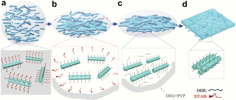
Herein, via manipulating the interaction between aliphatic ligands (e.g. 1-octadecene (ODE)) and nanorods (NRs) in the solution, we present an effcient bottom-up technology to fabricate free-standing 2D nanorafts by self-assembly of 1D NRs (Scheme 1). These 2D nanorafts possess lateral dimensions up to several micrometers and thickness of a few nanometers. Following a similar procedure, nanorafts with various compositions, such as MgF2, WO2, CdS, ZnS, and ZnSe, can be easily assembled from the corresponding 1D NR building blocks. This assembly process is template/substrate-free, and the resulting 2D nanorafts can be easily re-dispersed and free-floating in different kinds of solvents without any disassembly. These 2D nanorafts exhibit many intriguing properties. For example, strong adsorption capability was achieved from the high “porosity” endowed by the close-packing of the 1D NRs. As a demonstration of application, MgF2 nanorafts as a sensing platform have exhibited high fluorescence quenching effciency and strong affnity toward DNA. In general, our method circumvents the limitations, such as stability on certain substrates or poor mobility associated with traditional assembly techniques, and allows processing of the 2D assembled structures in various solvent environments, holding great potential for future fabrication of novel 2D devices.
Scheme 1.
Scheme for the formation of free-standing 2D nanorafts through the self-assembly of NRs.
Experimental section
Synthesis of free-standing 2D nanorafts from MgF2 NRs (diameters of ~7 nm and lengths of ~100 nm, Fig. S1a†)
In a typical self-assembly experiment, 20 μL 1-octadecene (ODE) was added into a hexane solution of MgF2 NRs (1 mg, 500 μL) by using a vortex mixer for 30 minutes. Then, a cationic surfactant (DTAB, 110 μL, 20 mg mL−1) solution was added to the mixture. Afterwards, the mixture was heated and vigorously agitated by vortexing to create a water-in-oil micro-emulsion (Fig. S2†). Subsequently, 1 mL diethylene glycol (DEG) containing 0.1 g of polyvinylpyrrolidone (PVP, Mw = 55 000) was added swiftly to the emulsion and subjected to vortexing for 2 minutes. The emulsion was then heated to 83 °C and kept at this temperature for 90 minutes to evaporate the residual hexane phase and then held for another 4.5 hours before the suspension was cooled to room temperature. Finally, the resulting products were washed several times with ethanol and methanol to remove impurities followed by centrifugation at 4000 rpm for 8 minutes and re-dispersal in ethanol prior to being characterized.
Using the same strategy, 5 μL, 15 μL and 30 μL ODE were used to stabilize NRs to form NR micelles prior to the self-assembly process.
For the synthesis of free-standing 2D nanorafts from WO2 NRs, CdS NRs, ZnS NRs, and ZnSe NRs, please see the ESI.†
Human thrombin assays
All fluorescence spectra were recorded at room temperature in a 2 mL tube with 20 μg nanorafts in a HORIBA Jobin Yvon fluorophotometer. FITC-labeled TBA (30 nM) was incubated with different amounts of human thrombin in a solution of 940 μL for 20 min. After the aforementioned solutions were incubated with MgF2 nanorafts (l, 40 μ 0.5 mg ml−1) for 5 min, fluorescence measurements of the mixtures were carried out in Tris-HCl buffer (20 mm, pH 7.4, containing 100 mM NaCl, 5 mM KCl, and 10 mM MgCl2) at room temperature. The final concentration of human thrombin ranged from 1 nM to 1000 nM. For kinetic study of fluorescence quenching, fluorescence spectra were recorded immediately after the addition of MgF2 nanorafts.
Results and discussion
The resulting products were isolated by centrifugation and characterized by transmission electron microscopy (TEM). Well-dispersed 2D quasi-nanosheets with lateral dimensions up to several micrometers could be observed (Fig. 1a). A magnified image of typical quasi-nanosheets (Fig. 1b and c, inset) further reveals that they are composed of densely packed 1D NRs (therefore these quasi-nanosheets are also called “nanorafts”). The thicknesses of the 2D nanorafts were further characterized by atomic force microscopy (AFM). The thickness of one typical nanoraft is measured to be ~66 nm (Fig. 1d and Fig. S3†). The selected area (electron) diffraction (SAED) pattern shows a diffused ring pattern, which indicates the “amorphous” feature (Fig. 1c). Furthermore, benefitting from this “amorphous” feature, these 2D nanorafts can be easily collected by simple centrifugation and could also be re-dispersed in different solvents (i.e., DI-water, ethanol) for more than 24 hours without disassembly, indicating their excellent stability and free-standing character (Fig. 1 and Fig. S4†).
Fig. 1.
TEM images of 2D MgF2 nanorafts: (a) low-magnification image; (b) and (c) high-magnification images and electron diffraction pattern (inset); (d) AFM image. Samples prepared from MgF2 NR assembly guided by 20 μL ODE and stored in ethanol.
As reported earlier,19 the formation of assembled 2D membranes has been realized at the liquid–air interface on substrates by evaporating a low-boiling solvent, such as hexane. Here, without any supporting substrate or template, free-standing 2D nanorafts can be assembled directly in solution. To realize a successful assembly, first of all, the presence of DTAB is a pre-requisite. As described previously, DTAB acts as a cationic surfactant to transfer ODE-capped NRs into hydrophilic solution by a ligand-wrapped reaction,20 forming NR micelles, i.e., amphiphilic micro-emulsions with an interdigitated bilayer structure (Fig. S2†).21 It is only with such a hydrophilic structure (the DTAB layer) that the NR micelles can be uniformly dispersed in mixed solvent (Fig. 3a).22 Otherwise, only irregular bulk aggregates can be formed, as shown in Fig. S5a.† During the heating process, this DTAB layer disassociates gradually by dissolving in the mixed solvent (Fig. 3b). The complete absence of DTAB in the final product can be confirmed from the1H NMR spectra, in which only signals of ODE can be detected from the surfaces of the NRs (Fig. S6†). After the dissociation of DTAB, many ODE-capped NRs were “wrapped” inside the mixed solvent (PVP and DEG) (Fig. 3c).
Fig. 3.
Scheme of the assembly process for 2D nanorafts from 1D NRs in solution: (a) NR-emulsion in mixed solvent (DEG and PVP); (b) self-dissociation of the DTAB layer and reformation of ODE-capping NRs; (c) ODE mediates NR assembly; (d) formation of 2D nanorafts.
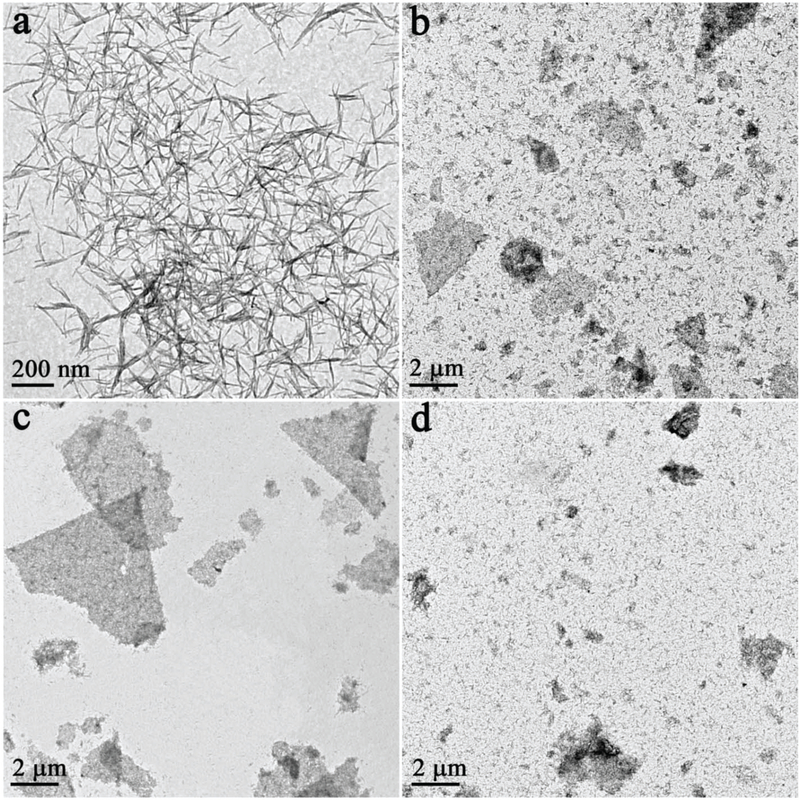
Second, the presence of PVP is also very important to initiate the assembly process. Without PVP, NRs aggregated into bulk products (Fig. S5b†). However, the key to the precise assembly of 1D NRs into 2D nanorafts lies in fine tuning the amount of ODE present in the solution (Fig. 2). Without ODE, no assembled products were collected using the same process (Fig. 2a). When 5 μL ODE was added, a loose lamellar product from NR assembly was observed (Fig. 2b). The yield of the lamellar product increased with the amount of ODE (e.g., Fig. 2c, 15 μL ODE). Stable and well-defined 2D nanorafts were assembled when the amount of ODE was further increased to 20 μL (Fig. 1), which later proved to be a critical point for the formation of 2D nanorafts (Fig. S7†). It is thus speculated that, in the formation of 2D nanorafts, there is a balance of the elastic repulsive force contributed by the ligands (ODE) and van der Waals attractive forces (please see the entropy analysis for this self-assembled mechanism in the ESI†).23–25 Here, one can liken the anisotropic van der Waals attraction among NRs to “glue”, while the ODE shows strong ligand elastic repulsion to alleviate inter-rod attractions, and stimulate NRs to spread and rearrange into 2D nanorafts in the solution (Fig. 3c andd).1,23,26 However, to a certain extent, when the van der Waals attractive forces are not suffcient to balance the strong ligand elastic repulsive forces (excessive ODE was added), the as-assembled nanorafts are no longer stable, eventually giving rise to disintegration of these lamellar 2D nano-structures into irregular debris (Fig. 2d).27
Fig. 2.
TEM images of the assembly process for free-standing 2D nanorafts. Samples prepared from the assembly of 1D NRs mediated by different amounts of ODE: (a) 0 μL; (b) 5 μL; (c) 15 μL; (d) 30 μL.
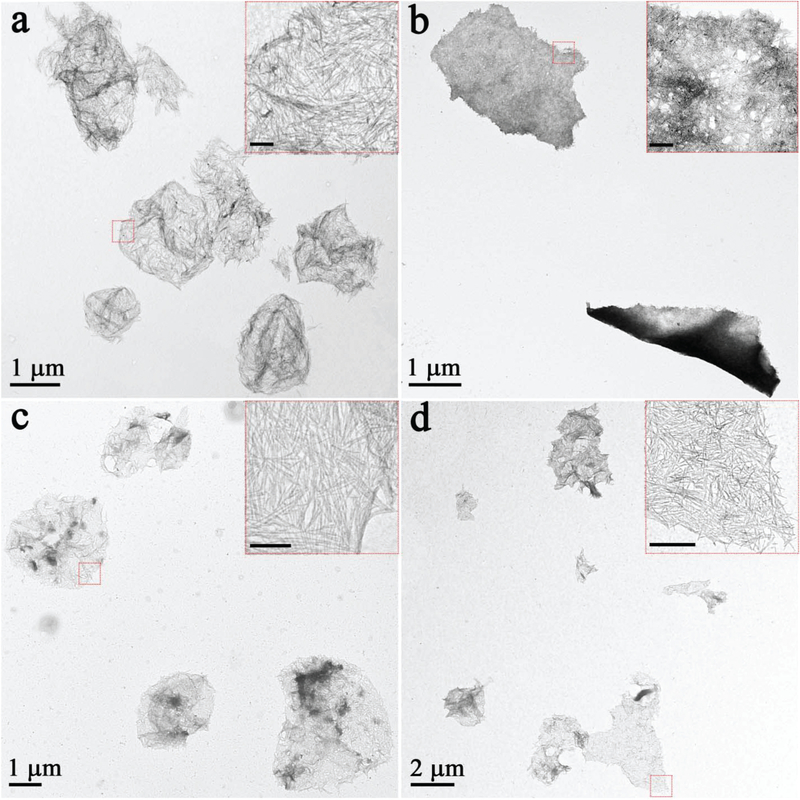
Based on the above mechanism, it is reasonable to expect the generalized application of this method to materials other than MgF2. For instance, free-standing WO2, CdS, ZnS, and ZnSe nanorafts were all successfully fabricated by simply changing the nanorod precursors (Fig. 4). As suggested above, the generality and flexibility of this method arise from the absence of a template or substrate and with the adjustment of one simple parameter: aliphatic ligands (ODE).
Fig. 4.
TEM images of 2D nanorafts with different compositions: (a) WO2 nanorafts; (b) CdS nanorafts; (c) ZnS nanorafts; (d) ZnSe nanorafts. The scale bars are 100 nm in inset images.
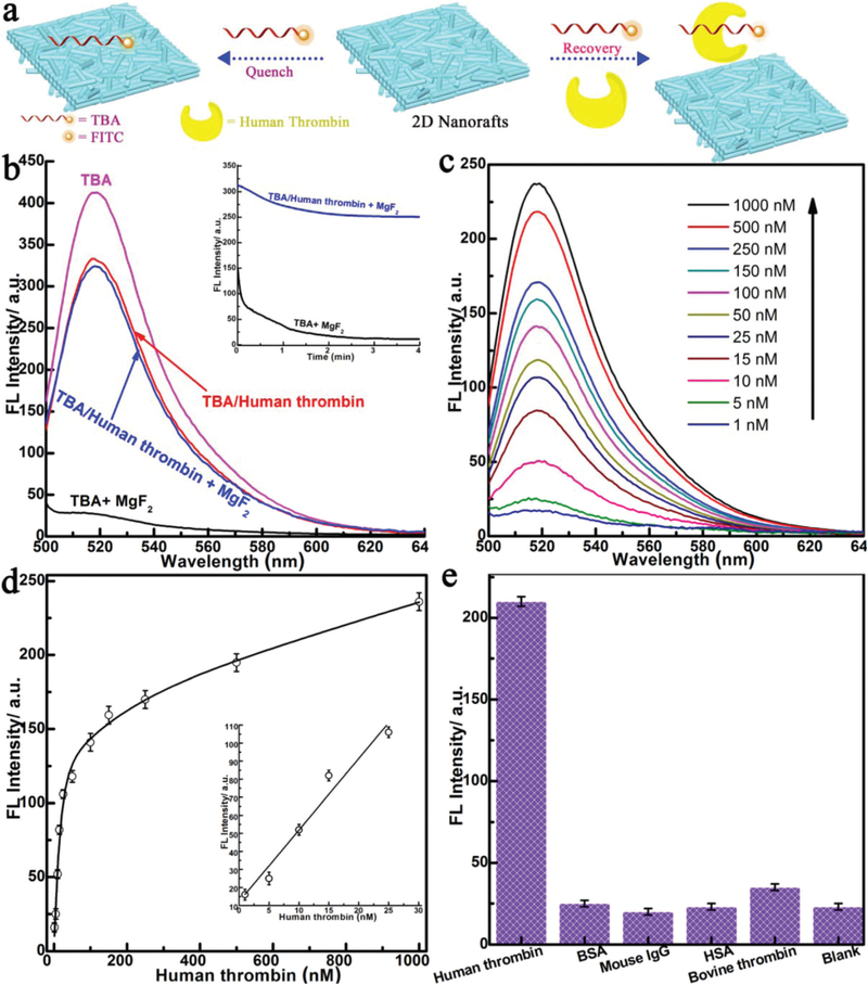
The unique structure of free-standing 2D nanorafts makes them promising for applications in diverse areas such as biological systems and sensors.28–30 Here, as a proof-of-principle application, we designed a simple platform to use 2D nano-rafts (MgF2) for the detection of proteins (human thrombin) (Fig. 5a). The fluorescein (FITC)-labeled human thrombin aptamer (TBA, 5’-TCTCTCAGTCCGTGGTAGGGCAGGTTG GGGTGACT-FITC-3’), which specifically binds to human thrombin with high affnity,31 was chosen as a model in this study. In the presence of 2D nanorafts, TBA fluorescence was almost entirely quenched, with up to 98% quenching effciency obtained within 3 minutes (TBA + MgF2 in Fig. 5b). This indicated that the 2D nanorafts possess excellent fluorescence quenching ability and very rapid quenching kinetics. This may be ascribed to the strong adsorption (attractive interaction) of nucleobases (DNA aptamer) onto the basal plane of the “porous” nanorafts (Fig. 1b and c),32 arising from strong van der Waals and immersion capillary forces. For comparison, the MgF2 NRs, which are the original building blocks, were also tested. No such adsorption or quenching of TBA fluorescence was observed, further highlighting the advantage of the nanorafts. Fig. 5c shows the fluorescence emission spectra of TBA after incubation with different concentrations of human thrombin and treatment with an aliquot of the 2D nanoraft solution. As seen in Fig. 5c, it is obvious that the fluorescence of TBA was intensified by increasing the human thrombin concentration. Additionally, the concentration of human thrombin was detectable down to 1 nM (Fig. 5d), and the linear range was from 1 nM to 25 nM, which is better than the values of the aptamer–GO and carbon nanotube complexes.31,33 The control experiments showed that only human thrombin produced strong fluorescence due to the specific affnity of TBA towards human thrombin, while the signal of other proteins was scarcely detected (Fig. 5e). This result clearly demonstrates that these aptamer–2D nanorafts can be used as a remarkably sensitive and selective platform for protein detection without the interference of other proteins.
Fig. 5.
(a) Schematic representation of target-induced fluorescence change of the TBA + 2D nanoraft (MgF2) (see text for details) (TBA is labeled with FITC, a fluorescein-based fluorescent dye); (b) fluorescence spectra of TBA (45 nM) and human thrombin (50 nM) in the absence and presence of 2D nanorafts (inset: kinetics study for the fluorescence change of TBA and TBA-targeted human thrombin in the presence of 2D nanorafts); (c) fluorescence spectra of TBA (30 nM) in the presence of different concentrations of human thrombin; (d) calibration curve for the detection of human thrombin (inset: amplification of the low concentration range (0 to 50 nM of the calibration curve)); (e) selectivity of the 2D nanoraft-based protein sensor toward different proteins. Excitation: 488 nm; emission: 520 nm.
Conclusions
We have developed an innovative method to assemble 1D NRs into free-standing 2D nanorafts in solution. These nanorafts possess lateral dimensions up to several micrometers and thicknesses of a few nanometers. It was confirmed that aliphatic ligands play a critical role in mediating the formation of the 2D nanorafts. The assembly process has endowed nanorafts with some unique features, such as high porosity and stability in both polar and non-polar solvents, making them suitable for a wide range of applications. As a general approach, 2D nanorafts with diverse compositions and size distributions, e.g. MgF2, WO2, CdS, ZnS, and ZnSe nanorafts, have been fabricated by self-assembly of their 1D building blocks. It is anticipated that this work can provide researchers in materials science with guidelines for the construction of free-standing 2D materials by assembly technology with huge potential for various applications.
Supplementary Material
Acknowledgements
The authors are grateful to Dr Kathryn Williams for her critical comments during the preparation of this manuscript. This work is supported by NSFC grants (NSFC 21521063), and by NIH GM R35 127130 and NSF 1645215, and by grants awarded by the Australian Research Council (ARC) Discovery Early Career Researcher Award (DECRA) (Project ID: DE160100589).
Footnotes
Conflicts of interest
There are no conflicts to declare.
Electronic supplementary information (ESI) available: Figures including NR building blocks, scheme of the formation of NR micelles, TEM and AFM images of 2D nanorafts, the stability of 2D nanorafts stored in different solvents and 1H NMR spectra (PDF). See DOI: 10.1039/c9nr02636c
Notes and references
- 1.Vogel N, Retsch M, Fustin C-A, del Campo A and Jonas U, Chem. Rev, 2015, 115, 6265–6311. [DOI] [PubMed] [Google Scholar]
- 2.Boles MA, Engel M and Talapin DV, Chem. Rev, 2016, 116, 11220–11289. [DOI] [PubMed] [Google Scholar]
- 3.Gong J, Newman RS, Engel M, Zhao M, Bian F,Glotzer SC and Tang Z, Nat. Commun, 2017, 8, 14038. [DOI] [PMC free article] [PubMed] [Google Scholar]
- 4.Ortega S, Ibáñez M, Liu Y, Zhang Y, Kovalenko MV,Cadavid D and Cabot A, Chem. Soc. Rev, 2017, 46, 3510–3528. [DOI] [PubMed] [Google Scholar]
- 5.Camden JP, Dieringer JA, Zhao J and Van Duyne RP, Acc. Chem. Res, 2008, 41, 1653–1661. [DOI] [PubMed] [Google Scholar]
- 6.Tseng RJ, Huang J, Ouyang J, Kaner RB and Yang Y, Nano Lett., 2005, 5, 1077–1080. [DOI] [PubMed] [Google Scholar]
- 7.Coe S, Woo WK, Bawendi M and Bulovic V, Electroluminescence from Single Monolayers of Nanocrystals in Molecular Organic Devices, Nature, 2002, 420, 800–803. [DOI] [PubMed] [Google Scholar]
- 8.Oregan B and Gratzel MA, Nature, 1991, 353, 737–740. [Google Scholar]
- 9.Sun SH, Murray CB, Weller D, Folks L and Moser A, Science, 2000, 287, 1989–1992. [DOI] [PubMed] [Google Scholar]
- 10.Castelli A, de Graaf J, Marras S, Brescia R, Goldoni L,Manna L and Arciniegas MP, Nat. Commun, 2018, 9, 1141. [DOI] [PMC free article] [PubMed] [Google Scholar]
- 11.Ye X and Qi L, Nano Today, 2011, 6, 608–631. [Google Scholar]
- 12.Takeda S and Wiltzius P, Chem. Mater, 2006, 18, 5643–5645. [Google Scholar]
- 13.Bigioni TP, Lin X-M, Nguyen TT, Corwin EI,Witten TA and Jaeger HM, Nat. Mater, 2006, 5, 265–270. [DOI] [PubMed] [Google Scholar]
- 14.Walker DA, Browne KP, Kowalczyk B and Grzybowski BA, Angew. Chem., Int. Ed, 2010, 49, 6760–6763. [DOI] [PubMed] [Google Scholar]
- 15.Zhang S-Y, Regulacio MD and Han M-Y, Chem. Soc. Rev, 2014, 43, 2301–2323. [DOI] [PubMed] [Google Scholar]
- 16.Lv R, Robinson JA, Schaak RE, Sun D, Sun Y,Mallouk TE and Terrones M, Acc. Chem. Res, 2015, 48, 56–64. [DOI] [PubMed] [Google Scholar]
- 17.Cai R, Yang D, Lin K-T, Lyu Y, Zhu B, He Z, Zhang L,Kitamura Y, Qiu L, Chen X, Zhao Y, Chen Z and Tan W,J. Am. Chem. Soc, 2019, 141(4), 1725–1734. [DOI] [PMC free article] [PubMed] [Google Scholar]
- 18.Sau TK, Rogach AL, Jäckel F, Klar TA and Feldmann J. Adv. Mater, 2010, 22, 1805–1825. [DOI] [PubMed] [Google Scholar]
- 19.Park YK, Yoo SH and Park S, Langmuir, 2007, 23, 10505–10510. [DOI] [PubMed] [Google Scholar]
- 20.Du Y, Yin Z, Zhu J, Huang X, Wu X-J, Zeng Z, Yan Q and Zhang H, Nat. Commun, 2012, 3, 1177. [DOI] [PubMed] [Google Scholar]
- 21.Fan H, Leve E, Gabaldon J, Wright A, Haddad RE and Brinker CJ, Adv. Mater, 2005, 17, 2587–2590. [Google Scholar]
- 22.Buzzaccaro S, Piazza R, Colombo J and Parola A, J. Chem. Phys, 2010, 132, 124902. [DOI] [PubMed] [Google Scholar]
- 23.Jenkins P and Snowden M, Adv. Colloid Interface Sci, 1996, 68, 57–96. [Google Scholar]
- 24.Asakura S and Oosawa F, J. Chem. Phys, 1954, 22, 1255–1256. [Google Scholar]
- 25.Young KL, Jones MR, Zhang J, Macfarlane RJ,Esquivel-Sirvent R, Nap RJ, Wu J, Schatz GC, Lee B and Mirkin CA, Proc. Natl. Acad. Sci. U. S. A, 2012, 109, 2240–2245. [DOI] [PMC free article] [PubMed] [Google Scholar]
- 26.Min Y, Akbulut M, Kristiansen K, Golan Y and Israelachvili J. Nat. Mater, 2008, 7, 527–538. [DOI] [PubMed] [Google Scholar]
- 27.Bodnarchuk MI, Kovalenko MV, Heiss W and Talapin DV, J. Am. Chem. Soc, 2010, 132, 11967–11977. [DOI] [PubMed] [Google Scholar]
- 28.Karim MR, Hatakeyama K, Matsui T, Takehira H,Taniguchi T, Koinuma M, Matsumoto Y, Akutagawa T,Nakamura T, Noro S-I, Yamada T, Kitagawa H and Hayami S, J. Am. Chem. Soc, 2013, 135, 8097–8100. [DOI] [PubMed] [Google Scholar]
- 29.Parvin N, Jin Q, Wei Y, Yu R, Zheng B, Huang L,Zhang Y, Wang L, Zhang H, Gao M, Zhao H, Hu W,Li Y and Wang D, Adv. Mater, 2017, 29, 1606755. [DOI] [PubMed] [Google Scholar]
- 30.Wei J, Wang G, Chen F, Bai M, Liang Y, Wang H,Zhao D and Zhao Y, Angew. Chem., Int. Ed, 2018, 57, 9838–9843. [DOI] [PubMed] [Google Scholar]
- 31.Lu C-H, Yang H-H, Zhu C-L, Chen X and Chen G-N, Angew. Chem., Int. Ed, 2009, 48, 4785–4787. [DOI] [PubMed] [Google Scholar]
- 32.Zhu C, Zeng Z, Li H, Li F, Fan C and Zhang H, J. Am. Chem. Soc, 2013, 135, 5998–5600. [DOI] [PubMed] [Google Scholar]
- 33.Yang R, Jin J, Chen Y, Shao N, Kang H, Xiao Z, Tang Z,Wu Y, Zhu Z and Tan W, J. Am. Chem. Soc, 2008, 130, 8351–8358. [DOI] [PubMed] [Google Scholar]
Associated Data
This section collects any data citations, data availability statements, or supplementary materials included in this article.


