Abstract
In this work, the design, fabrication, and characterization of piezoelectric micromachined ultrasound transducer (PMUT) arrays for photoacoustic imaging applications are reported. An 80-element linear PMUT array with each element having 53 PMUT cells of 125 μm cell diameter were fabricated using 650 nm thick lead zirconate titanate (PZT) as the active piezoelectric layer. The PMUTs are designed to operate at ~10 MHz resonant frequency. The PMUT elements are validated for photoacoustic imaging using an agar gel phantom with embedded pencil leads as the imaging target. Photoacoustic A-line response of the targets captured by single PMUT element shows ~7 MHz center frequency with ~4.8 MHz bandwidth. B-mode images reconstructed from A-lines recorded during the linear scanning of a single element clearly imaged all the targets, thus validating the potential of the fabricated PMUTs for photoacoustic imaging.
Keywords: PMUTs, MEMS, Ultrasound Transducers, Photoacoustic Imaging
I. Introduction
Photoacoustic imaging (PAI) is a hybrid imaging modality that exploits the principle of photoacoustic effect, conversion of light to sound, to map optical absorption-based molecular contrast images of deep tissue with ultrasonic spatial resolution. Over the last decade, PAI has made significant progress in several pre-clinical and clinical applications due to the development and integration of better instrumentation (e.g., novel optoacoustic transducer designs) and reconstruction algorithms [1]–[8], Furthermore, since PAI shares the same detection platform as widely adopted ultrasound imaging, integrated ultrasound and photoacoustic imaging systems with hand held devices were developed for simultaneously displaying anatomical and molecular contrasts in tissue [9]–[12], Bulk piezoelectric transducers are the current standard in all these applications. However, the realization of wearable, portable or micro-endoscopy PAI devices necessitates the use of miniaturized ultrasound transducers and their compact integration with optical components and associated front-end electronics. Micromachined ultrasonic transducer (MUT) arrays, fabricated using micro-electro-mechanical systems (MEMS) technology, that can be directly bonded to application specific integrated circuits (ASICs) with ease [13]–[17], are ideally suited for such miniaturized devices. The small footprint of integrated MUT-ASICs leaves sufficient room for optimal routing of optical components, such as fiber coupled lasers, to deliver light into the deep tissue. MUTs should also have a low cost and good reproducibility due to batch fabrication processing. Due to reduced power requirements and ease of on-chip processing, such systems will also allow miniaturization of required electronics and power subsystems. Low cost portable PAI systems will be useful for point-of-care imaging applications and thus complement more conventional imaging technologies such as magnetic resonance imaging (MRI) and positron emission tomography (PET).
Two prominent contenders for MUTs are capacitive micro machined ultrasound transducers (CMUTs) and piezoelectric micromachined ultrasound transducers (PMUTs) [18], [19], While some successful efforts have been reported earlier on developing PAI systems with CMUTs, comparable attempts with PMUTs are at a very early stage. Only one report so far shows photoacoustic imaging with a PMUT element experimentally; however, the results were limited to a transmission geometry with a very thin imaging phantom, and without any mention about the specification of the array [19]. A few other reports have hypothesized PMUTs as a potential candidate for PAI but without any accompanying experimental verification [20]–[22].
In this paper, first, the fabrication process for a linear PMUT array with 125 μm cell diameter and thin film PZT as the active piezoelectric material is described. After basic characterization, the PMUTs were wire-bonded to a pin grid array (PGA) socket and tested for photoacoustic imaging. A linear scanning of a single PMUT element in the array, to emulate a full linear array, provided B-mode images of an agar-gel phantom with embedded pencil leads acting as the photoacoustic targets.
II. Design and Fabrication
A PMUT is a multilayered plate structure, generally circular in shape, with an embedded piezoelectric thin film. The material stack layout used in this work for fabricating the PMUT is shown in Fig. 1. High frequency PMUTs, as desired for PAI, can be achieved by either reducing the radius of the suspended membrane or by increasing its thickness. Since the PMUT is being used in the receive only mode in PAI, a thick substrate layer with thin PZT layer, will lead to overall higher charge output due to higher average stress in the PZT layer, as descried earlier [23], Hence, a 10 μm thick device layer silicon-on-insulator (SOI) wafer was chosen as the substrate for device fabrication.
Fig. 1.
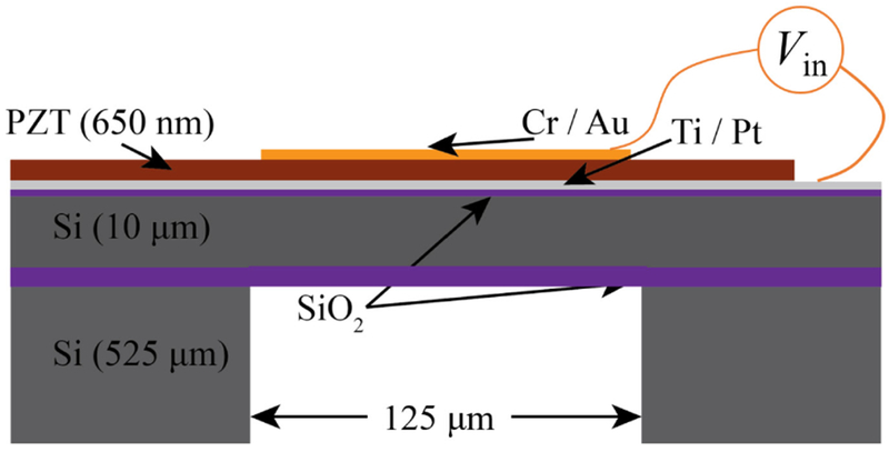
A schematic representation of the design of a single cell in the piezoelectric micromachined ultrasound transducer (PMUT) array and various material layers in suspended membrane.
The first resonant frequency, ω, of the PMUT is given as
| (1) |
where, α is the frequency parameter (equal to 3.196 for a clamped circular plate), a is the radius of the PMUT, ρi and hi are the density and the thickness of the ith layer in the material stack, and De is the equivalent flexural rigidity of the multilayered plate structure [23], Using (1), the first resonance was determined to be 10.2 MHz for a 125 μm cell diameter PMUT, which is desirable for photoacoustic applications [15], [24], [25], A linear array of PMUTs was designed to achieve maximum fill-density of PMUT cells within the fabrication constraints. Along the width of the linear array, a column of 35 PMUT cells kept at 175 μm center-to-center distance are shorted together to fonn one element. 80 such elements are arranged along the length of the PMUT array in a staggered fashion to obtain an 80-element PMUT array with 152 μm element pitch (Fig. 2).
Fig. 2.
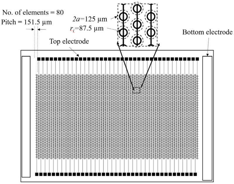
A schematic representation of an 80-element linear array of PMUTs with 35 cells per element each having 125 um diameter designed in a staggered pattern with 175 um center-to-center distance between each PMUT cell.
The fabrication process starts by first growing a 100 nm thick SiO2 on both sides of the SOI wafer by thermal oxidation process. Following this, 20 nm Ti and 150 nm Pt were sputtered on the top surface. The Ti/Pt layer functions as the base for piezoelectric thin film deposition and serves as the bottom electrode of the device. PZT (52/48) was chosen as the material for the active piezoelectric thin film due to its high piezoelectric coefficient and ease of deposition [26], Approximately, a 650 nm thick PZT thin film was deposited on a platinized SOI wafer by using sol-gel process. The chemical solution for PZT was obtained by mixing lead acetate trihydrate, zirconium propoxide, and titanium butoxide in a 2-methoxyethanol solution using a method described earlier [26], The sol-gel deposition process involved 8 cycles of spin coating of PZT solution followed by a two-step heating process at the end of each coat solvent removal and pyrolysis of the PZT, followed by 30 minutes of annealing at 650 °C for recrystallization. The glancing angle x-ray diffraction (XRD) plot of the deposited PZT thin film showed peaks corresponding to the perovskite phase (Fig. 3).
Fig. 3.
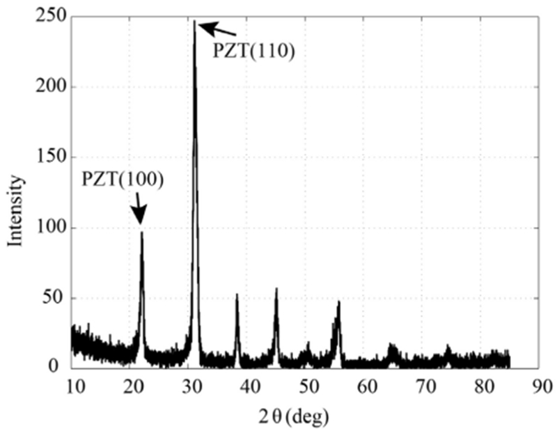
Glancing angle XRD plot of the sol-gel deposited PZT shows the desired perovskite phase.
A Cr (10 nm) / Au (150 nm) layer is coated on the top of the PZT layer to function as the top electrode. On application of voltage between the top gold and bottom platinum electrode, in-plane mechanical stress is generated in the PZT layer due to the piezoelectric effect. This leads to a net bending moment along the periphery of the top electrode. For optimal vibration of the PMUT, the bending moment should act at 65-70% of the suspended circular plate [23]. In this case, the top electrode covered 70% of the PMUT area. The PZT layer was etched only at the edge of the array to access the bottom electrode. In order to release the 175 μm diameter of the device material stack, first a 4 μm thick SiO2 mask was obtained on the backside of the PMUT by deposition of a thick SiO2 layer by plasma enhanced chemical vapor deposition (PECVD) followed by reactive ion etching of the circular area to expose the structural silicon layer from the backside. Using patterned backside SiO2 layer as the mask, the structural silicon was released using deep reactive ion etching (DRIE). The fabricated PMUTs were then wire bonded to a pin grid array (PGA) socket and coated with 1.5 μm thick parylene (Fig. 4). The parylene coating acts as a protective layer that insulates the device from the surrounding fluid/tissue hence improving the biocompatibility and avoiding undesirable parasitic capacitance. Finally, the PMUTs are poled by applying a 9 V DC voltage across the top and bottom electrode for 10 minutes.
Fig. 4.
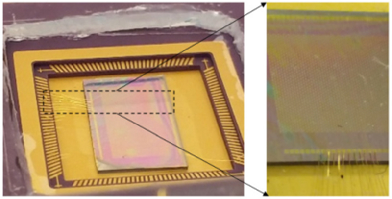
Optical picture of the linear PMUT array wire bonded to a PGA socket.
III. Photoacoustic Imaging
A schematic representation of the PAI experimental setup with PMUTs is shown in Fig. 5a. The wire bonded PMUT array was fixed to the bottom of a transparent tank filled with deionized water. An agar gel phantom with four embedded 0.7 mm pencil leads was submerged into the water tank. A custom designed light guide connected to a tunable nanosecond pulsed laser (Phocus Mobile by Opotek Inc.) was mounted next to a sidewall of the tank to irradiate the sample. The laser generates a ~100 mJ light pulse at 10 Hz repetition rate. The acoustic pressure generated by the pencil leads due to light absorption was picked by that PMUTs and captured using a high-speed data acquisition system (Razonnax 16, Gage Instruments) after 39 dB gain using a typical ultrasound pre-amplifier (Olympus 5073). Typical A-line photoacoustic signal from the phantom is shown in Fig. 5c. The frequency transfonn of the received photoacoustic signal from the pencil lead (dotted box) (inset of Fig. 5c) shows ~7 MHz center frequency with ~68% -6dB fractional bandwidth. The lower than expected resonant frequency can be attributed to mass loading due to water.
Fig. 5.

Experimental setup for photoacoustic imaging (PAI). (a) Schematic diagram of PAI experimental setup using PMUTs. (b) Picture of the setup showing the agarose gel phantom, PMUTs array, light-guide, and embedded pencil lead targets, (c) Photoacoustic A-line signal detected by the PMUT element after 39 dB gain, from a pencil lead placed ~2.3 cm away, on excitation by the laser source. The inset shows the frequency response of the photoacoustic pulse with center frequency of ~7 MHz and approximately 68% fractional bandwidth.
Since the pre-amplifier and data acquisition electronics is currently limited to only few channels, for the purpose of initial validation a single PMUT element in the 80-element PMUT array was used for image generation. In order to capture a B-mode image of the phantom, the phantom was attached to a 3-axis xyz translation stage and scanned in steps of 200 μm for 120 steps along the length direction of the PMUT array, while capturing A-line photoacoustic signals at each position. The 120 A-lines thus captured emulate a 120 element linear array with 200 μm pitch which is achievable in fabrication. The A-line data was processed through a delay-and-sum algorithm to generate the B-mode image of the phantom as shown in Fig. 6. The B-mode photoacoustic image of the agar-gel phantom clearly shows pencil-lead targets at their expected positions. The lateral and axial resolutions estimated from the half value of 90 % to 10 % drop in the signal intensity along the edge of a pencil lead target (T3) were found to be ~600 μm and ~190 μm respectively.
Fig. 6.
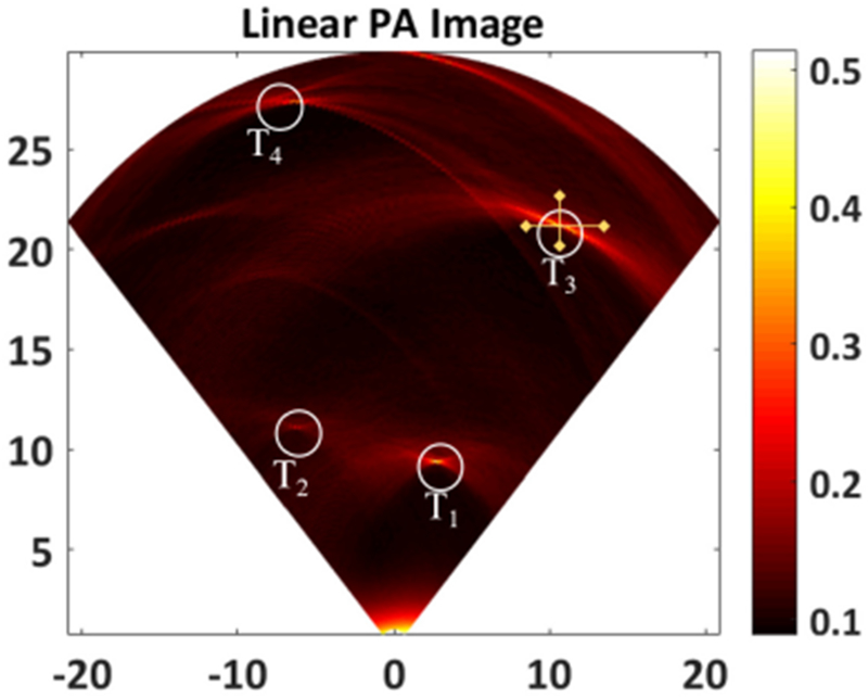
B-mode photoacoustic image reconstructed from 120 A-lines obtained from a linear scanning of the PMUT element. Circles T1, T2, T3 and T4 clearly show the photoacoustic contrast from 4 pencil lead targets embedded inside the agar phantom. The cross-hairs on T3 show the lines along which lateral and axial resolutions were calculated.
IV. Conclusions
A linear PMUT array with 125 μm cell diameter was designed for PAI applications. The array was successfully fabricated using standard MEMS approach. After subsequent packaging, a single PMUT element was tested for photoacoustic imaging capabilities by using an agar-gel phantom with embedded pencil leads as light absorbing imaging targets. The A-line signals show sharp pulse response centered ( ~ 7 MHz) lower than the expected 10 MHz frequency. A B-mode photoacoustic image was reconstructed using 120 A-line signals recorded while scanning the phantom with a single PMUT element. The generated photoacoustic image could clearly distinguish the embedded pencil lead targets, thus demonstrating the feasibility of the fabricated linear arrays for photoacoustic imaging. Rigorous instrumentation (e.g., multichannel data acquisition) and further validation in various imaging conditions will be carried out using the PMUTs in near future. The reported approach has the potential to develop miniaturized PAI systems.
Acknowledgment
This work is supported by the National Institute of Biomedical Imaging and Bioengineering (NIBIB), National Institute of Health (NIH), U.S. under Grant R00EB017729-04 (SRK).
The authors would like to thank Antony Jeyaseelan, and Soma Dutta at CSIR, National Aerospace Laboratories, India for their help in the PZT thin film development.
References
- [1].Wang LV and Hu S, “Photoacoustic tomography: In vivo imaging from organelles to organs,” Science (80-. )., vol. 335, no. 6075, pp. 1458–1462, 2012. [DOI] [PMC free article] [PubMed] [Google Scholar]
- [2].Xu M and Wang LV, “Photoacoustic imaging in biomedicine,” Review of Scientific Instruments, vol. 77, no. 4 2006. [Google Scholar]
- [3].Valluru KS and Willmann JK, “Clinical photoacoustic imaging of cancer,” Ultrasonography, vol. 35, no. 4, pp. 267–280, 2016. [DOI] [PMC free article] [PubMed] [Google Scholar]
- [4].Dogra VS et al. , “Multispectral Photoacoustic Imaging of Prostate Cancer: Preliminary Ex-vivo Results.,” J. Clin. Imaging Sci, vol. 3, no. 1, p. 41, 2013. [DOI] [PMC free article] [PubMed] [Google Scholar]
- [5].Wang X, Roberts WW, Carson PL, Wood DP, and Fowlkes JB, “Photoacoustic tomography: a potential new tool for prostate cancer,” Biomed. Opt. Express, vol. 1, no. 4, p. 1117, 2010. [DOI] [PMC free article] [PubMed] [Google Scholar]
- [6].Kitai T et al. , “Photoacoustic mammography: Initial clinical results,” Breast Cancer, vol. 21, no. 2, pp. 146–153, 2014. [DOI] [PubMed] [Google Scholar]
- [7].Wang LV, “Prospects of photoacoustic tomography,” Medical Physics, vol. 35, no. 12 pp. 5758–5767, 2008. [DOI] [PMC free article] [PubMed] [Google Scholar]
- [8].Beard P, “Biomedical photoacoustic imaging,” Interface Focus, vol. 1, no. 4, pp. 602–631, 2011. [DOI] [PMC free article] [PubMed] [Google Scholar]
- [9].Kumavor PD et al. , “Co-registered pulse-echo/photoacoustic transvaginal probe for real time imaging of ovarian tissue,” J. Biophotonics, 2013. [DOI] [PMC free article] [PubMed] [Google Scholar]
- [10].Garcia-Uribe A et al. , “Dual-Modality photoacoustic and ultrasound imaging system for noninvasive sentinel lymph node detection in patients with breast cancer,” Sci. Rep, 2015. [DOI] [PMC free article] [PubMed] [Google Scholar]
- [11].Wang X, Roberts WW, Carson PL, Wood DP, and Fowlkes JB, “Photoacoustic tomography: a potential new tool for prostate cancer,” Biomed. Opt. Express, 2010. [DOI] [PMC free article] [PubMed] [Google Scholar]
- [12].Yaseen MA, “Optoacoustic imaging of the prostate: development toward image-guided biopsy,” J. Biomed. Opt, 2010. [DOI] [PMC free article] [PubMed] [Google Scholar]
- [13].Zahorian J et al. , “Monolithic CMUT-on-CMOS integration for intravascular ultrasound applications,” IEEE Trans. Ultrason. Ferroelectr. Freq. Control, vol. 58, no. 12, pp. 2659–2667, 2011. [DOI] [PMC free article] [PubMed] [Google Scholar]
- [14].Dausch DE, Gilchrist KH, Carlson JB, Hall SD, Castellucci JB, and Von Ramm OT, “In vivo real-time 3-D intracardiac echo using PMUT arrays,” IEEE Trans. Ultrason. Ferroelectr. Freq. Control, vol. 61, no. 10, pp. 1754–1764, 2014. [DOI] [PubMed] [Google Scholar]
- [15].Kothapalli SR, Ma TJ, Vaithilingam S, Oralkan O, Khuri-Yakub BT, and Gambhir SS, “Deep Tissue Photoacoustic Imaging Using a Miniaturized 2-D Capacitive Micromachined Ultrasonic Transducer Array,” IEEE Trans. Biomed. Eng, vol. 59, no. 5, pp. 1199–1204, 2012. [DOI] [PMC free article] [PubMed] [Google Scholar]
- [16].Nikoozadeh A et al. , “An integrated Ring CMUT array for endoscopic ultrasound and photoacoustic imaging,” in IEEE International Ultrasonics Symposium, IUS, 2013, pp. 1178–1181. [Google Scholar]
- [17].Oralkan Ö et al. , “Volumetric ultrasound imaging using 2-D CMUT arrays,” IEEE Trans. Ultrason. Ferroelectr. Freq. Control, vol. 50, no. 11, pp. 1581–1594, 2003. [DOI] [PubMed] [Google Scholar]
- [18].Qiu Y et al. , “Piezoelectric micromachined ultrasound transducer (PMUT) arrays for integrated sensing, actuation and imaging,” Sensors (Switzerland), vol. 15, no. 4 pp. 8020–8041, 2015. [DOI] [PMC free article] [PubMed] [Google Scholar]
- [19].Chen B, Chu F, Liu X, Li Y, Rong J, and Jiang H, “AIN-based piezoelectric micromachined ultrasonic transducer for photoacoustic imaging,” Appl. Phys. Lett, vol. 103, no. 3, 2013. [Google Scholar]
- [20].Liao W et al. , “Piezeoelectric micromachined ultrasound tranducer array for photoacoustic imaging,” in 2013 Transducers and Eurosensors XXVII: The 17th International Conference on Solid-State Sensors, Actuators and Microsystems, TRANSDUCERS and EUROSENSORS 2013, 2013. [Google Scholar]
- [21].Ahn H, Sung M, Been K, and Moon W, “Design and fabrication of a piezoelectric micromachined ultrasound array transducer for photoacoustic imaging applications,” in 2014 11th International Conference on Ubiquitous Robots and Ambient Intelligence, URAI 2014, 1997. [Google Scholar]
- [22].Liu S, Feng X, Ruochong Z, and Zheng Y, “Portable photoacoustic system for noninvasive blood temperature measurement,” in 2018 IEEE International Symposium on Circuits and Systems (ISCAS), 2018, pp. 1–5. [Google Scholar]
- [23].Dangi A and Pratap R, “System level modeling and design maps of PMUTs with residual stresses,” Sensors Actuators A Phys, vol. 262, pp. 18–28, Aug. 2017. [Google Scholar]
- [24].Kothapalli SR et al. , “Human prostate imaging using a novel integrated transrectal ultrasound and photoacoustic instrument,” Mol. Imaging Biol, vol. 15, no. 1, pp. S1447–S1448, 2013. [Google Scholar]
- [25].Kothapalli SR et al. , “Simultaneous Transrectal Ultrasound and Photoacoustic Imaging : A New Approach for Imaging the Human Prostate,” (Under Review) [Google Scholar]
- [26].Dutta S, Antony Jeyaseelan A, and Sruthi S, “Ferroelectric and Piezoelectric properties of (111) oriented lanthanum modified lead zirconate titanate film,” Thin Solid Films, vol. 562, pp. 190–194, 2014. [Google Scholar]


