Abstract
Purpose:
Sodium MRI has shown promise for monitoring neoadjuvant chemotherapy (NACT) response in breast cancer. The purpose of this work was to build a dual tuned bilateral 1H/23Na breast coil for 7T MRI that provides sufficient SNR to enable sodium breast imaging in less than 10 min.
Methods:
The 1H/23Na coil consists of two shielded unilateral units, one for each breast. Each unit is composed by three nested layers: (1) a three-loop solenoid for sodium excitation, (2) a three-loop solenoid for proton excitation and reception and (3) a four-channel receive array for sodium signal reception. Benchmark measurements were performed in phantoms with and without the sodium receive array insert. In vivo images were acquired on a healthy volunteer.
Results:
The sodium receive array boosted 1.5–3× the SNR compared to the solenoid. Proton SNR loss due to residual interaction with the sodium array was <10%. The coil enabled sodium imaging in vivo with 2.8 mm isotropic nominal resolution (~5 mm real resolution) in 9:36 min.
Conclusion:
The coil design that we propose addresses challenges associated with sodium’s low SNR from a hardware perspective and offers the opportunity to investigate non-invasively breast tumor metabolism as function of sodium concentration in patients undergoing NACT.
Keywords: Multi-nuclei coil, breast MRI, sodium (23Na) MRI, bilateral breast coil, high-field MRI
Introduction
Despite advances in diagnostic and therapeutic techniques, breast cancer remains the second leading cause of cancer death among women worldwide (1). Most women with breast cancer undergo a lumpectomy in order to remove the tumor mass or a mastectomy in more extensive diseases (2). Neoadjuvant therapy is defined as the first step of therapy and is given before the main treatment, i.e. surgery, to shrink inoperable tumors, promote breast-conserving surgery or to treat aggressive subtypes of tumors. For breast cancer, it may include chemotherapy, radiation therapy, and hormone therapy. (3,4). While dynamic contrast enhanced MRI (DCE-MRI) is the most sensitive imaging tool to detect residual tumors following neoadjuvant chemotherapy (NACT) (5–10), its moderate specificity (~83%) impedes an accurate prediction on pathologic complete response (pCR) (11–13). One explanation is that the structural information such as tumor size, cellularity and vascularity (14,15) provided by DCE-MRI do not sufficiently reflect the metabolic underpinnings of the tumor. Further, breast tissue enhancement may be seen secondary to inflammatory changes from neoadjuvant chemotherapy, making the distinction between post-treatment changes and residual tumor clinically challenging.
Sodium MRI (23Na MRI) directly probes changes in ion homeostasis, i.e. the maintenance of the concentration gradient of ions across the cell membrane, which is strongly related to cellular metabolism, and has shown promise to detect malignancy and monitor NACT response. Prior studies showed that the total sodium concentration (TSC) was significantly greater in malignant breast lesions (+ 50–60%) compared to healthy tissues (16–18), while distinct trends were observed in chemotherapy responders (− 20–30%) compared to non-responders (+ 5–10%) (19,20).
Due to low sodium content in the body (approximately 15 mM inside the cells and 140 mM outside), its low MR sensitivity (9.27% of that of hydrogen) and short transversal relaxation times in biological tissues (T2,short = 1–5 ms, T2,long = 10–60 ms), 23Na MRI suffers from intrinsically low signal-to-noise ratio (SNR), which can be roughly 20,000 times lower than that of proton (21). Such low SNR translates into low spatial resolution to increase the signal detected in each voxel, and long acquisition times due to data averaging. Efforts to alleviate these challenges generally utilize high field systems (≥ 3 T), ultra-short echo time (UTE) acquisition methods, and tailored radiofrequency coils to boost the baseline SNR (22–24). This work will focus on the coil design aspect. Specifically, we designed a dual-tuned multichannel 1H/23Na bilateral breast coil consisting of volume transmit/receive (Tx/Rx) 1H coils, volume 23Na transmit coils and an 8-channel 23Na receive array for 7 T MRI.
Sodium MRI examinations typically include complementary proton acquisitions for anatomical localization and other desired contrasts. Radiofrequency coils that are sensitive to both sodium and proton signals in the breast have been developed in the past (25). However, most were limited to either unilateral coverage and/or clinical field strength (16,20,26,27). We implemented a 7 T dual-tuned coil with twin shielded unilateral units to provide bilateral coverage, which is the gold standard in the clinic due to the desire for a paired control measurement in the contralateral breast. In addition, the sodium receive array is tightly fitted to the breast and contains four detectors per breast, which provides a SNR advantage over a volume coil.
A key consideration in dual-tuned coil design is the mitigation of the interaction between the sodium and proton coils. The 1H coil, whose resonance frequency is higher than that of sodium, produces counter-rotating current in the 23Na coil that can disrupt the 1H coil performance. To mitigate this interference the sodium detectors are outfitted with proton “trap” circuits to diminish induced currents (28,29). In this work, we describe the coil design and provide benchmark performance measurements in phantoms and in vivo images.
Methods
Coil overview
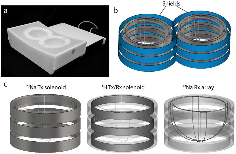
The 1H/23Na bilateral breast coil consists of two unilateral units, one for each breast. The two units and the associated circuitry are integrated into a tailored plastic housing that includes two dome cavities (posterior diameter = 14.5 cm, depth = 10 cm and volume ~2 L) to accommodate the breasts (Figure 1a).
Figure 1:
(a) The 1H/23Na bilateral breast coil in its tailored housing. (b) Left and right units were separated by two RF shields (in blue) which reduced coupling enabling bilateral operation. (c) Each unit of the coil is constituted by three layers. From the outermost to the innermost: a three-turns series solenoid for 23Na transmission, a three-turns series solenoid for 1H excitation and reception and a four-channel 23Na receive array. For sake of simplicity the series connection among the loops as well as the lumped elements are not reported.
Because of proximity, coupling between the two unilateral units caused peak resonance splitting. We addressed this problem by surrounding each unit by a passive conductive radiofrequency (RF) shield (diameter = 20.5 cm, height = 11.5 and 13 cm in the medial and in the lateral regions, respectively) to enable bilateral operation (Figure 1b). The conductive paths were broken up into sections that were bridged by high value capacitors in order to reduce gradient-induced eddy currents while maintaining RF transparency. Scattering (S) parameters were measured with the network analyzer to assess decoupling between left and right solenoids (both proton and sodium).
Each unit is composed by three nested layers (Figure 1c): (1) the outermost layer is a three-loop solenoid for sodium excitation, (2) the intermediate layer is a three-loop solenoid for proton excitation and reception and (3) innermost layer, the closest to the breast, is a four-channel receive array for sodium signal reception.
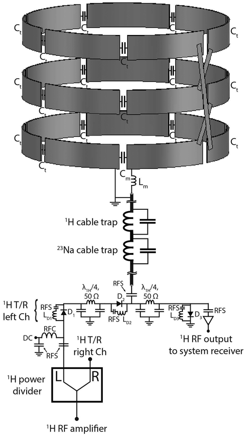
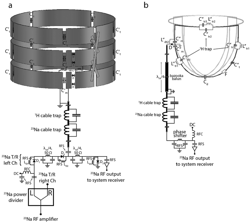
Detailed circuit schematics of the left unit of the 1H transmit/receive coil and 23Na transmit coil and receive array are presented respectively in Figures 2 and 3. The 23Na transmit solenoid and the 1H transmit/receive solenoid have similar interfaces. In both cases, a two-way power divider equally splits the waveform from the RF power amplifiers in order to feed left and right units.
Figure 2:
Circuit schematic of the 1H transmit/receive coil and interface. For simplicity, only the schematic of the left unit is illustrated. The left and right units were fed through a two ways power divider. The status of the DC bias is forward in transmit mode and reverse in receive mode. Cable traps tuned to 297.2 MHz and 78.6 MHz were implemented to reject common mode currents. The three loops of the 1H solenoid were connected in series. RFC: radiofrequency choke; RFS: radiofrequency short.
Figure 3:
Circuit schematic of the 23Na transmit coil and 23Na receive array with interface. (a) The 23Na transmit solenoid. The interface of the 23Na transmit solenoid has a similar setup as the one implemented for the 1H transmit/receive solenoid. T/R switches were implemented in order to enable reception with the 23Na solenoids to facilitate debugging; the array is used for signal reception during normal operation. The three loops of the 23Na solenoid were connected in series. Series diodes D in two locations were used to detune the solenoids when receiving with the array. (b) 23Na receive array. Cable traps tuned to the two frequencies of interest were implemented on the interface along with bazooka baluns on coaxial cables longer than a quarter-wavelength between the coil and the interface. Each 23Na coil included three proton traps to suppress 1H currents, an active detuning circuit and a fuse F. RFC: radiofrequency choke; RFS: radiofrequency short.
The 23Na transmit solenoid interface included a transmit/receive switch to enable signal reception. SNR and B1+ measurements were performed before implementing the 23Na receive array. This data was used as a baseline to assess the SNR advantage of the sodium array over the volume coils and the interaction between the array and the volume coils. All imaging experiments were performed on Siemens 7 T whole-body scanner (MAGNETOM, Siemens Healthineers, Erlangen, Germany).
23Na bilateral receive array
We built the eight-channel 23Na receive array on a domed substrate in order to encircle the breast and maximize SNR. The channel count and geometry were selected to provide suitable coverage, access to convenient decoupling methods, and sufficient ratio between sample and conductor noise at 78.6 MHz (30). For each unilateral unit, we built four triangular loop coils with 45 cm perimeter that were mounted on a 3D-printed dome shaped support (polycarbonate material, Fortus 360mc, Stratasys, Eden Prairie, MN). The coils were symmetrically distributed on the dome to provide encircling coverage, with all neighbors decoupled by partial overlap (-19.0 dB). The coils were tapered toward a common point at the dome apex, which provided a convenient location to decouple non-adjacent neighbors using local shared capacitors (-21.5dB). The quality factor (Q) was measured by loosely coupling a double magnetic field probe to the coils while they were unloaded and loaded with a tailored breast phantom whose dielectric properties represented a mixture of adipose and fibro-glandular breast tissue (σ = 0.30 S/m, εr = 40) (Table 1) (31).
Table 1:
Unloaded and loaded Q and resonance frequency for the coils in isolation and in the final setup (nested). A breast-mimicking phantom (conductivity σ = 0.30 S/m, relative permittivity εr = 40 at 297.2 MHz) was used in the loaded measurements. The frequencies reported below each Q ratio refer to the loaded case. Tx: Transmit; Rx: Receive.
|
1H isolated |
23Na isolated |
1H/23Na nested |
|
|---|---|---|---|
| 1H Tx/Rx solenoid | 79:14 (200.0 MHz) |
- | 325:15 (297.2 MHz) |
| 23Na Tx solenoid | - | 607:101 (50.0 MHz) |
419:130 (78.6 MHz) |
| 23Na Rx 14 cm loop | - | 330:150 (77.3 MHz) |
290:140 (78.6 MHz) |
During sodium excitation, the receive array was detuned with one active high impedance circuit at each port. A fuse provided redundant protection in the event of an active detuning circuit failure. In order to reduce interaction between the 23Na receive coils and the 1H coils, blocking “trap” circuits with high impedance at proton frequency were added to the 23Na loops (28,29). The optimal number of blocking circuits was determined by building 14 cm diameter test loops with different 1H trap counts (1 to 3). For each loop the coil noise as well as the 1H current mitigation (in terms of frequency shift of a 1H loop coil in the presence of the 23Na coils) were measured. We found that three proton traps per loop were sufficient to block 1H currents while containing the Q ratio penalty on the 23Na coils.
The 23Na receive-only coils were connected to the interface through tri-axial cables that were outfitted with “bazooka” cable traps (32) to suppress common mode currents at the proton frequency and subsequent cable traps tuned to both sodium and proton frequencies. Preamplifier decoupling was achieved by adjusting the effective electrical length between the coils and preamplifiers using coaxial cable and lumped elements phase shifters.
Sodium SNR maps in phantom were calculated from images acquired with a 2D gradient echo pulse sequence (sequence parameters: TR/TE = 200/2.46 ms, FA = 90°, 8 averages, in-plane resolution 7×7 mm2, slice thickness = 25 mm, TA = 1:44 min) and noise data acquired with the same sequence but with the RF pulse amplitude set to zero. The data were reconstructed using the optimal combination method (33). SNR maps were acquired with and without the receive array inserts to estimate the gain provided by the receive array over the 23Na solenoids (described in the following section).
23Na transmit array
Sodium excitation was achieved with two three-turns solenoids (conductor width = 3 cm, diameter =19 cm, height = 10 cm), whose turns were each connected in series. We implemented solenoids because their geometry is suitable to generate a uniform and linearly polarized B1 field in the breast.
The two solenoids were driven through a two-way power divider and subsequent transmit/receive switches that allowed signal reception for coil debugging and comparison with the receive array. During 23Na reception with the 8-channel array, the solenoids were detuned by applying reverse DC bias to a set of PIN diodes in series with the solenoids.
To perform bilateral imaging, we surrounded each solenoid with a RF shield to mitigate interaction between the two units. Nonetheless, the residual coupling (-12 dB) was sufficient to cause B1+ interference patterns that depended on the relative phase difference between left and right units. We found that a zero phase difference maximized B1+ per unit volt and B1+ symmetry between the two units.
In order to assess transmit efficiency and uniformity, sodium B1+ maps were calculated from a series of gradient echo images acquired with a range of pulse amplitudes by voxel-wise fitting a sine curve to the signal intensities. Six gradient echo acquisitions with a range of pulse voltages were performed with the following sequence parameters: TR/TE = 200/6.51 ms, 3 averages, in-plane resolution 7×7 mm2, slice thickness = 25 mm, TA = 0:40 min. B1+ maps were acquired with and without the 23Na receive array in place to evaluate their interaction. The B1+ field uniformity in a central transverse slice was reported as 1 minus the standard deviation of B1+ in a 2D region of interest (ROI) that included the whole phantom, divided by its mean in the same ROI: .
1H transmit/receive array
Two three-turns solenoids (conductor width = 2 cm, diameter =17.6 cm, and height = 9 cm) tuned to 297.2 MHz were implemented to enable seamless high-resolution 1H imaging and to determine B0 shim settings. The 1H solenoids served for both excitation and reception.
As radiation loss scales with the 4th power of the frequency and the square of the coil area (34,35), its contribution was significant in comparison to sample loss for the 1H solenoids due to their size and operating frequency (36). We found that nesting the 1H Tx/Rx solenoids within the 23Na solenoids and RF shields reduced radiation loss and provided −36 dB isolation between the left and right units.
Proton B1+ maps were acquired using the same approach described earlier for 23Na (sequence parameters: TR/TE = 1000/2.56 ms, in-plane resolution 2.8×2.8 mm2, slice thickness = 5 mm, TA = 1:38 min per scan). Proton SNR maps were calculated from signal maps acquired with a gradient echo pulse sequence (sequence parameters: TR/TE = 1000/3.54 ms, FA = 20°, in-plane resolution 2.8×2.8 mm2, slice thickness = 5 mm, TA = 1:38 min) and noise data acquired with the same sequence but with zero RF pulse amplitude. The 1H SNR maps were then scaled in order to account for B1+ variation throughout the volume by the formula: SNR = SNRraw/sin(α), where α is the flip angle and SNRraw is the SNR calculated as described earlier. Proton B1+ and SNR maps were acquired with and without the 23Na receive array to assess the interaction between the two devices. The coil geometry factor (g) was derived from SNR data to assess parallel imaging performance (37).
Imaging experiments
Due to the short bi-exponential T2 relaxation of sodium in vivo, we acquired sodium data with the Fermat looped orthogonally encoded trajectories (FLORET) (38) UTE pulse sequence to minimize the loss of signal between RF excitation and data acquisition.
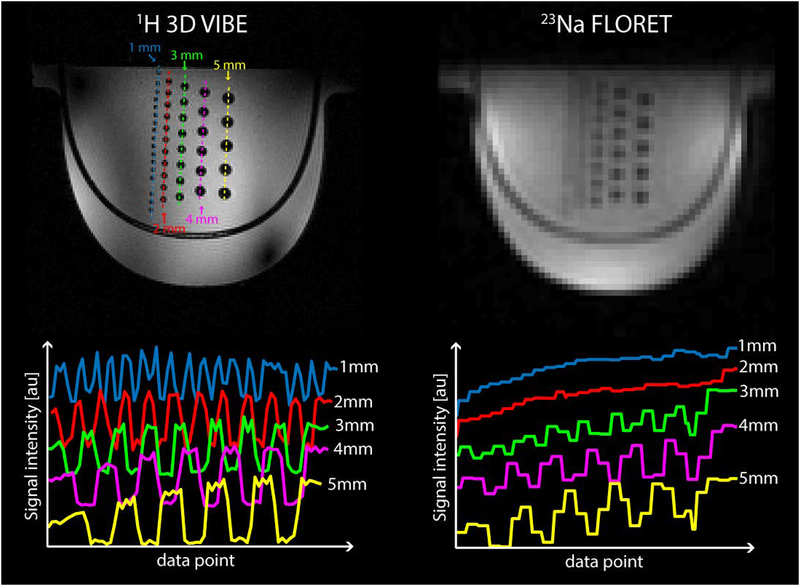
We built a resolution phantom to test 23Na protocol feasibility and to estimate the experimental point spread function of the sequence. The phantom was filled with a 120 mM of phosphate buffered saline (PBS) solution and embedded with five rows of glass rods with diameters ranging from 1 to 5 mm with 1 mm step size and spacing equal to their diameters. Sodium images were acquired using FLORET sequence with the following parameters: TR/TE = 50/0.2 ms, flip angle = 80°, 3 hubs of 400 interleaves, 5 averages, acquisition duration (ADC) = 16 ms, isotropic (theoretical) base resolution = 2.9 mm, FOV = 370 mm (isotropic), TA = 5:00 min. The TE is here defined as the time between the end of the RF pulse and the beginning of the data acquisition with the ADC. High resolution 1H images were also acquired with a 3D gradient echo sequence with the following parameters: TR/TE = 7/2.04 ms, FA = 5°, voxel size 1.0×1.0×1.0 mm3, TA = 3:40 min.
Our Institutional Review Board approved the study and the coil was employed to acquire in vivo images on a 24-years-old healthy woman after obtaining her informed written consent. Standard fat-suppressed T1-weighted proton images were acquired with a 3D gradient echo sequence that was optimized for 7 T with the following parameters: TR/TE = 7/2.14 ms, FA = 4°, voxel size 1.2×0.9×1 mm3, acceleration factor (iPAT) = 2, TA = 3:50 min (36,39). Sodium images were acquired with a FLORET sequence with TR/TE = 60/0.2 ms, FA = 80 °, 3 hubs, 400 interleaves, isotropic nominal resolution 2.8 mm, 8 averages, TA = 9:36 min.
Results
The shielded bilateral solenoids had unloaded to loaded Q ratios of 3.2 for 23Na and 21.7 for 1H (Table 1). Compared to the isolated environment, the nested configuration resulted in increased efficiency that was primarily due to reduced radiation loss for the 1H solenoid (Q ratio = 5.6) and somewhat reduced efficiency for the 23Na solenoid (Q ratio = 6.0). It has to be pointed out that the 23Na coils shielding effect also caused the 1H solenoid resonance frequency to shift from 200.0 MHz to 297.2 MHz which contributed to the increased Q ratio. The unloaded to loaded Q ratio of the 23Na receive loops in isolation was 2.2, with negligible effect from the surrounding solenoids and shield. The corresponding coil noise expressed as percentage of the total noise was: (40). We found that three high-impedance proton traps in the 23Na receive array sufficiently reduced the interaction with the 1H solenoid (<0.5 MHz shift in the 1H resonance frequency), which resulted in a minimal coil noise penalty (8.6% decrease in Q ratio).
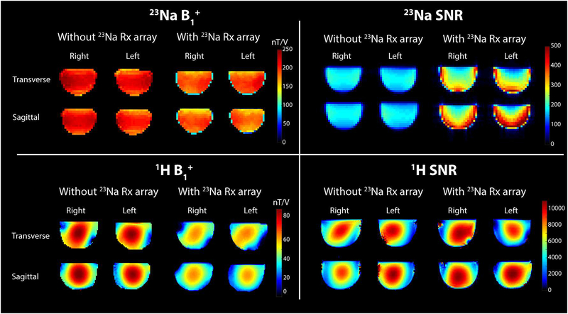
The 23Na receive array provided a ~40% SNR gain in the center of the phantom and a ~3-fold gain in the periphery compared to the solenoid, illustrating the benefit of the tight-fitting multi-channel array (Figure 4). The excitation field generated by the 23Na solenoid was 212.6 +/− 19.6 nT/V without the receive array and 188.9 +/− 21.8 nT/V with the array, indicating some interaction between the solenoid, array and associated cabling. Nonetheless, the excitation field was adequately uniform and efficient for imaging.
Figure 4:
Top: 23Na B1+ map (left) and SNR map (right) with and without the 23Na receive array. Bottom: 1H B1+ map (left) and SNR map (right) with and without the 23Na receive array.
The drop in 1H SNR when the 23Na Rx array was inserted was <10%. Although the insertion of the 23Na receive array caused a drop in B1+ intensity for both nuclei, it did not alter considerably the overall field distribution: the field uniformity calculated in a central transverse slice within the phantoms was u = 0.80 for the 23Na solenoids and u = 0.65 for the 1H solenoids in both configurations. Such modest B1+ uniformity for the 1H solenoids is not surprising at 7 T and can be primarily attributed to the short wavelength in the dielectric sample that leads to interference patterns (41–44). The maximum geometry factor (g) for 1H acquisition with two-fold acceleration in the left-right direction was 1.14.
Figure 5 shows the images acquired with the resolution phantom with the 1H 3D GRE sequence (left) and 23Na FLORET sequence (right). The signal profiles across each column of rods (dotted lines) are plotted below their respective 1H and 23Na images. All rods from 1 to 5-mm diameter are well resolved on 1H image. In the sodium image, the 4- and 5-mm diameter rods are well resolved while those with diameter smaller than 3 mm cannot be clearly distinguished. This is in accordance with the 23Na FLORET sequence whose point spread function (PSF) of ~1.8 voxels full width at half maximum (FWHM) and nominal sequence resolution of 2.9 mm isotropic results in a real resolution of ~5.2 mm.
Figure 5:
1H 3D GRE (top left) and 23Na FLORET (top right) images acquired on a resolution phantom with glass rod inserts with diameters ranging from 1 to 5 mm. The signal profiles across each column of rods shows 1 mm diameter rods are resolved in 1H images (bottom left) while 4 and 5 mm rods are well resolved in 23Na images (bottom right) This is in accordance with the 23Na FLORET sequence point spread function (PSF) of ~1.8 voxel full width at half maximum (FWHM), and nominal sequence resolution of 2.9 mm isotropic, which results in a real resolution of ~ 5.2 mm.
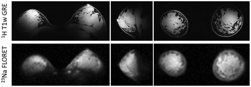
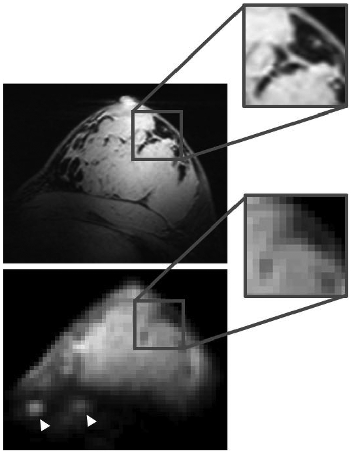
For both nuclei in vivo images show good B1+ symmetry between left and right sides and adequate coverage within the breasts, which gradually decays towards the axillary regions and in the area between the breasts (Figure 6). Proton B1+ distribution was sufficiently uniform to provide good fat suppression. The 23Na images allow discrimination between the breast parenchyma and fat tissue, which has low sodium content. Figure 7 shows enlarged details in the co-registered 1H and 23Na images. Sodium low resolution inevitably causes partial volume effect artifacts, especially at the boundaries between parenchyma and fat tissue, however anatomical details such as fat pockets within the glandular tissue, which are very well captured in the high resolution 1H images, can be identified in the 23Na images. Local regions of high intensity (white arrowheads in Figure 7) are observed in correspondence to the costal cartilage, which is known to have substantial sodium content (21,45).
Figure 6:
Three-plane view of 1H T1w fat-suppressed 3D gradient echo (top row) and co-localized 23Na FLORET (bottom row) images. The sodium images (2.8 mm isotropic resolution, TA 9:36 min) distinguish fibroglandular tissue (hyperintense) from fat tissue (hypointense).
Figure 7:
Enlarged details in the co-registered 1H T1w GRE (top) and 23Na FLORET (bottom). Despite the low 23Na resolution some fine anatomical details can be identified, such as regional “fat pockets” and rib cartilage in the chest wall (white arrowheads).
Discussion
In this work we proposed a dual-tuned 1H/23Na coil for bilateral breast MRI at 7 T. The dedicated 8-channel sodium receive array was key to obtain a 1.5–3× improvement in SNR compared to a volume receive coil, which enabled bilateral, whole-volume in vivo imaging with 2.8 mm isotropic resolution in less than 10 minutes. This performance is on par with low field clinical standards and is anticipated to allow 23Na metabolic characterization in lesions larger than ~ 5 mm. The dual-tuned coil additionally provided ~ 1 mm isotropic 1H images for complementary anatomical and DCE kinetic analysis.
Our 23Na imaging efficiency (22 μL voxels in 9.5 mins) is comparable to that reported by Zaric, et al. (11 μL voxels in 16.5 mins) (27), which is to the best of our knowledge the only other demonstration of 23Na bilateral breast MRI at 7 T. While Zaric, et al. provided promising 23Na and diffusion measurements in tumors, we focused on the coil design. Our coil utilized a close-fitting 23Na receive array to achieve high SNR, but also created a challenging environment for the 1H solenoids due to the opportunity to induce current in the 23Na array and therefore perturb the 1H B1 field. To mitigate this interaction, we inserted trap circuits that resonated at the 1H frequency (28,46,47). The resulting 23Na coil noise penalty was reduced by the minimizing the number of traps, which depends on the size of the 23Na coil as well as the blocking frequency; we found that for a 14 cm diameter loop three 1H traps equidistantly spaced around the coil were necessary to reduce the 1H frequency shift below 0.5 MHz and reduce 1H B1+ distortions. With this configuration, the coils in our eight-channel array were on the edge of sample noise dominance, therefore limiting the appeal of an array with smaller coils and additional channels. We also found that the 1H B1+ and SNR distributions were sensitive to the trap orientation and 23Na array cable routing. To minimize the disturbance, we orientated the inductors in the high-impedance traps orthogonal to local magnetic field of the 1H solenoid and routed cables radially outward from the array through the shield.
Whereas most 23Na breast MRI has been limited to unilateral coverage, another essential feature of the presented coil is its expanded FOV to both breasts. Bilateral imaging is important for accurate staging of the extent of local breast cancer and because asymmetric response of the breasts is often seen in pre-menopausal women and women who have undergone radiation therapy. We enabled bilateral coverage by enclosing the left and right unilateral coils into RF shields that eliminated resonance frequency splitting. Note that we did not observe image distortions that could result from gradient-induced eddy currents in the RF shields, which might be anticipated in the 23Na FLORET acquisition that necessitates fast switching gradients to generate spiral trajectories. The use of dual shielded transmit solenoids was a straightforward way to achieve locally high B1+ across the bilateral FOV. The chosen design is not subject to the bimodal B1+ asymmetry that is typical of breast MRI at 3 T, which affects fat suppression uniformity and most importantly causes significant variation in contrast enhancement, making differential diagnosis difficult (36,48–51).
While the 23Na solenoids provided good coverage, 1H coverage was confined primarily to the breast and degraded toward the axillary and chest wall regions. This is a common weakness in 7 T 1H breast MRI (36,39,52,53) that has been addressed with dedicated hardware (54,55). In the case of our design, space constraints for the multiple bilateral coil layers may have accentuated its compressed local field pattern.
The metabolic information accessible with 23Na MRI could be valuable in assessing breast cancer response to therapy. Several studies have shown significant decrease of malignant tumor total sodium content in NACT responders, which makes sodium concentration a good candidate to monitor therapy response. Moreover, high 23Na SNR acquisitions could enable access to even more specific biomarkers of cellular metabolism such as intracellular sodium concentration, and cellular density such as extracellular volume fraction (56), that are still largely unexplored due to the challenges associated with sodium’s low abundance in the body and low MR receptivity. The coil design that we proposed in this work attempts to address these challenges from a hardware perspective and offers the opportunity to investigate non-invasively breast tumor metabolism as function of sodium concentration (and/or volume fraction) in patients undergoing NACT. This valuable information could inform the tumor response to NACT and provide guidance to patient-specific therapy plans.
Acknowledgements.
The authors thank Jerzy Walczyk for help with the coil housing and Riccardo Lattanzi for the SNR calculation tool. This work was partially supported by National Institutes of Health grants R01DK106292, R21AG061579, R01DK114428, R01NS097494, R21CA213169, R01EB026456 and was performed under the rubric of the Center for Advanced Imaging Innovation and Research (CAI2R, www.cai2r.net) at the New York University School of Medicine, which is an NIBIB Biomedical Technology Resource Center (NIH P41 EB017183).
References
- 1.DeSantis CE, Ma J, Goding Sauer A, Newman LA, Jemal A. Breast cancer statistics, 2017, racial disparity in mortality by state. CA: a cancer journal for clinicians 2017;67(6):439–448. [DOI] [PubMed] [Google Scholar]
- 2.American Cancer Society, Breast Cancer Facts & Figures 2017–2018. Atlanta: American Cancer Society, Inc; 2017. [Google Scholar]
- 3.Holmes D, Colfry A, Czerniecki B, Dickson-Witmer D, Espinel CF, Feldman E, Gallagher K, Greenup R, Herrmann V, Kuerer H, Malik M, Manahan E, O’Neill J, Patel M, Sebastian M, Wheeler A, Kass R. Performance and Practice Guideline for the Use of Neoadjuvant Systemic Therapy in the Management of Breast Cancer. Ann Surg Oncol 2015;22(10):3184–3190. [DOI] [PubMed] [Google Scholar]
- 4.Gralow JR, Burstein HJ, Wood W, Hortobagyi GN, Gianni L, von Minckwitz G, Buzdar AU, Smith IE, Symmans WF, Singh B, Winer EP. Preoperative therapy in invasive breast cancer: pathologic assessment and systemic therapy issues in operable disease. Journal of clinical oncology : official journal of the American Society of Clinical Oncology 2008;26(5):814–819. [DOI] [PubMed] [Google Scholar]
- 5.Drisis S, Metens T, Ignatiadis M, Stathopoulos K, Chao SL, Lemort M. Quantitative DCE-MRI for prediction of pathological complete response following neoadjuvant treatment for locally advanced breast cancer: the impact of breast cancer subtypes on the diagnostic accuracy. Eur Radiol 2016;26(5):1474–1484. [DOI] [PubMed] [Google Scholar]
- 6.Gruber S, Pinker K, Zaric O, Minarikova L, Chmelik M, Baltzer P, Boubela RN, Helbich T, Bogner W, Trattnig S. Dynamic contrast-enhanced magnetic resonance imaging of breast tumors at 3 and 7 T: a comparison. Invest Radiol 2014;49(5):354–362. [DOI] [PubMed] [Google Scholar]
- 7.Hahn SY, Ko EY, Han BK, Shin JH, Ko ES. Role of diffusion-weighted imaging as an adjunct to contrast-enhanced breast MRI in evaluating residual breast cancer following neoadjuvant chemotherapy. Eur J Radiol 2014;83(2):283–288. [DOI] [PubMed] [Google Scholar]
- 8.Li X, Arlinghaus LR, Ayers GD, Chakravarthy AB, Abramson RG, Abramson VG, Atuegwu N, Farley J, Mayer IA, Kelley MC, Meszoely IM, Means-Powell J, Grau AM, Sanders M, Bhave SR, Yankeelov TE. DCE-MRI analysis methods for predicting the response of breast cancer to neoadjuvant chemotherapy: pilot study findings. Magnetic resonance in medicine 2014;71(4):1592–1602. [DOI] [PMC free article] [PubMed] [Google Scholar]
- 9.Yankeelov TE, Lepage M, Chakravarthy A, Broome EE, Niermann KJ, Kelley MC, Meszoely I, Mayer IA, Herman CR, McManus K, Price RR, Gore JC. Integration of quantitative DCE-MRI and ADC mapping to monitor treatment response in human breast cancer: initial results. Magnetic resonance imaging 2007;25(1):1–13. [DOI] [PMC free article] [PubMed] [Google Scholar]
- 10.Menezes GL, Knuttel FM, Stehouwer BL, Pijnappel RM, van den Bosch MA. Magnetic resonance imaging in breast cancer: A literature review and future perspectives. World J Clin Oncol 2014;5(2):61–70. [DOI] [PMC free article] [PubMed] [Google Scholar]
- 11.Pinker K, Helbich TH, Morris EA. The potential of multiparametric MRI of the breast. Br J Radiol 2017;90(1069):20160715. [DOI] [PMC free article] [PubMed] [Google Scholar]
- 12.Tateishi U, Miyake M, Nagaoka T, Terauchi T, Kubota K, Kinoshita T, Daisaki H, Macapinlac HA. Neoadjuvant chemotherapy in breast cancer: prediction of pathologic response with PET/CT and dynamic contrast-enhanced MR imaging--prospective assessment. Radiology 2012;263(1):53–63. [DOI] [PubMed] [Google Scholar]
- 13.Zhang L, Tang M, Min Z, Lu J, Lei X, Zhang X. Accuracy of combined dynamic contrast-enhanced magnetic resonance imaging and diffusion-weighted imaging for breast cancer detection: a meta-analysis. Acta Radiol 2016;57(6):651–660. [DOI] [PubMed] [Google Scholar]
- 14.Pickles MD, Lowry M, Manton DJ, Gibbs P, Turnbull LW. Role of dynamic contrast enhanced MRI in monitoring early response of locally advanced breast cancer to neoadjuvant chemotherapy. Breast cancer research and treatment 2005;91(1):1–10. [DOI] [PubMed] [Google Scholar]
- 15.DeMartini W, Lehman C. A review of current evidence-based clinical applications for breast magnetic resonance imaging. Topics in magnetic resonance imaging : TMRI 2008;19(3):143–150. [DOI] [PubMed] [Google Scholar]
- 16.Ouwerkerk R, Jacobs MA, Macura KJ, Wolff AC, Stearns V, Mezban SD, Khouri NF, Bluemke DA, Bottomley PA. Elevated tissue sodium concentration in malignant breast lesions detected with non-invasive 23Na MRI. Breast cancer research and treatment 2007;106(2):151–160. [DOI] [PubMed] [Google Scholar]
- 17.Cameron IL, Smith NK, Pool TB, Sparks RL. Intracellular concentration of sodium and other elements as related to mitogenesis and oncogenesis in vivo. Cancer Res 1980;40(5):1493–1500. [PubMed] [Google Scholar]
- 18.Li L, Li P, Fang J, Li Q, Xiao H, Zhou H, Tang B. Simultaneous Quantitation of Na(+) and K(+) in Single Normal and Cancer Cells Using a New Near-Infrared Fluorescent Probe. Anal Chem 2015;87(12):6057–6063. [DOI] [PubMed] [Google Scholar]
- 19.Jacobs MA, Ouwerkerk R, Wolff AC, Gabrielson E, Warzecha H, Jeter S, Bluemke DA, Wahl R, Stearns V. Monitoring of neoadjuvant chemotherapy using multiparametric, (2)(3)Na sodium MR, and multimodality (PET/CT/MRI) imaging in locally advanced breast cancer. Breast cancer research and treatment 2011;128(1):119–126. [DOI] [PMC free article] [PubMed] [Google Scholar]
- 20.Jacobs MA, Ouwerkerk R, Wolff AC, Stearns V, Bottomley PA, Barker PB, Argani P, Khouri N, Davidson NE, Bhujwalla ZM, Bluemke DA. Multiparametric and multinuclear magnetic resonance imaging of human breast cancer: current applications. Technology in cancer research & treatment 2004;3(6):543–550. [DOI] [PubMed] [Google Scholar]
- 21.Madelin G, Regatte RR. Biomedical applications of sodium MRI in vivo. Journal of Magnetic Resonance Imaging 2013;38(3):511–529. [DOI] [PMC free article] [PubMed] [Google Scholar]
- 22.Shajan G, Mirkes C, Buckenmaier K, Hoffmann J, Pohmann R, Scheffler K. Three-layered radio frequency coil arrangement for sodium MRI of the human brain at 9.4 Tesla. Magnetic resonance in medicine 2015. [DOI] [PubMed] [Google Scholar]
- 23.Mirkes CC, Hoffmann J, Shajan G, Pohmann R, Scheffler K. High-resolution quantitative sodium imaging at 9.4 Tesla. Magnetic resonance in medicine 2015;73(1):342–351. [DOI] [PubMed] [Google Scholar]
- 24.Kraff O, Fischer A, Nagel AM, Monninghoff C, Ladd ME. MRI at 7 Tesla and above: demonstrated and potential capabilities. Journal of magnetic resonance imaging : JMRI 2015;41(1):13–33. [DOI] [PubMed] [Google Scholar]
- 25.Yang X, Handa S, Zheng T, Lawrie C, Finnerty M, Herczak J, Fujita H, Bogner W, Zaric O, Zbyn S, Trattnig S. A Dual-Tune Sodium/Proton Tx/Rx 14-channel Sodium and 2-channel Proton Array Breast Coil at 7T. ISMRM; 2013:2785. [Google Scholar]
- 26.Kaggie JD, Hadley JR, Badal J, Campbell JR, Park DJ, Parker DL, Morrell G, Newbould RD, Wood AF, Bangerter NK. A 3 T sodium and proton composite array breast coil. Magnetic resonance in medicine 2014;71(6):2231–2242. [DOI] [PMC free article] [PubMed] [Google Scholar]
- 27.Zaric O, Pinker K, Zbyn S, Strasser B, Robinson S, Minarikova L, Gruber S, Farr A, Singer C, Helbich TH, Trattnig S, Bogner W. Quantitative Sodium MR Imaging at 7 T: Initial Results and Comparison with Diffusion-weighted Imaging in Patients with Breast Tumors. Radiology 2016;280(1):39–48. [DOI] [PubMed] [Google Scholar]
- 28.Dabirzadeh A, McDougall MP. Trap Design for Insertable Second-Nuclei Radiofrequency Coils for Magnetic Resonance Imaging and Spectroscopy. Concepts in Magnetic Resonance Part B (Magnetic Resonance Engineering), 2009;35B(3):121–132. [Google Scholar]
- 29.Meyerspeer M, Roig ES, Gruetter R, Magill AW. An improved trap design for decoupling multinuclear RF coils. Magnetic resonance in medicine 2014;72(2):584–590. [DOI] [PubMed] [Google Scholar]
- 30.Axel L, Hayes C. Surface coil magnetic resonance imaging. Arch Int Physiol Biochim 1985;93(5):11–18. [DOI] [PubMed] [Google Scholar]
- 31.Ianniello C, de Zwart JA, Duan Q, Deniz CM, Alon L, Lee J, Lattanzi R, Brown R. Synthesized tissue-equivalent dielectric phantoms using salt and polyvinylpyrrolidone solutions. Magnetic resonance in medicine 2017. [DOI] [PMC free article] [PubMed] [Google Scholar]
- 32.Schaller BM, Magill AW, Gruetter R. Common modes and cable traps. ISMRM; 2011. p 4660. [Google Scholar]
- 33.Roemer PB, Edelstein WA, Hayes CE, Souza SP, Mueller OM. The NMR phased array. Magn Reson Med 1990;16(2):192–225. [DOI] [PubMed] [Google Scholar]
- 34.Duan Q, Sodickson DK, Zhang B, Wiggins CG. A Comprehensive Coil Resistance Composition Model for High Field. 12th Annual Scientific Meeting of the International Society of Magnetic Resonance in Medicine Stockholm 2010. [Google Scholar]
- 35.Thomas VJ. Ultra High Field MRI: High-Frequency Coils In: Springer, editor. Ultra High Field Magnetic Resonance Imaging; 2006. [Google Scholar]
- 36.Brown R, Storey P, Geppert C, McGorty K, Klautau Leite AP, Babb J, Sodickson DK, Wiggins GC, Moy L. Breast MRI at 7 Tesla with a bilateral coil and robust fat suppression. Journal of magnetic resonance imaging : JMRI 2014;39(3):540–549. [DOI] [PMC free article] [PubMed] [Google Scholar]
- 37.Pruessmann KP, Weiger M, Scheidegger MB, Boesiger P. SENSE: sensitivity encoding for fast MRI. Magnetic resonance in medicine 1999;42(5):952–962. [PubMed] [Google Scholar]
- 38.Pipe JG, Zwart NR, Aboussouan EA, Robison RK, Devaraj A, Johnson KO. A new design and rationale for 3D orthogonally oversampled k-space trajectories. Magnetic resonance in medicine 2011;66(5):1303–1311. [DOI] [PubMed] [Google Scholar]
- 39.Brown R, Storey P, Geppert C, McGorty K, Leite AP, Babb J, Sodickson DK, Wiggins GC, Moy L. Breast MRI at 7 Tesla with a bilateral coil and T1-weighted acquisition with robust fat suppression: image evaluation and comparison with 3 Tesla. Eur Radiol 2013;23(11):2969–2978. [DOI] [PMC free article] [PubMed] [Google Scholar]
- 40.Hayes CE, Axel L. Noise performance of surface coils for magnetic resonance imaging at 1.5 T. Medical physics 1985;12(5):604–607. [DOI] [PubMed] [Google Scholar]
- 41.Roschmann P, Jensen D. Imaging of dielectric resonance mode patterns with a 4 tesla whole-body MR system. 1988. August 20–26, 1988; San Francisco, CA, USA. [Google Scholar]
- 42.Keltner JR, Carlson JW, Roos MS, Wong ST, Wong TL, Budinger TF. Electromagnetic fields of surface coil in vivo NMR at high frequencies. Magnetic resonance in medicine 1991;22(2):467–480. [DOI] [PubMed] [Google Scholar]
- 43.Collins CM, Liu W, Schreiber W, Yang QX, Smith MB. Central brightening due to constructive interference with, without, and despite dielectric resonance. Journal of magnetic resonance imaging : JMRI 2005;21(2):192–196. [DOI] [PubMed] [Google Scholar]
- 44.Vaidya MV, Collins CM, Sodickson DK, Brown R, Wiggins GC, Lattanzi R. Dependence of B1+ and B1- Field Patterns of Surface Coils on the Electrical Properties of the Sample and the MR Operating Frequency. Concepts in magnetic resonance Part B, Magnetic resonance engineering 2016;46(1):25–40. [DOI] [PMC free article] [PubMed] [Google Scholar]
- 45.Zbyn S, Mlynarik V, Juras V, Szomolanyi P, Trattnig S. Sodium MR Imaging of Articular Cartilage Pathologies. Curr Radiol Rep 2014;2:41. [DOI] [PMC free article] [PubMed] [Google Scholar]
- 46.Alecci M, Romanzetti S, Kaffanke J, Celik A, Wegener HP, Shah NJ. Practical design of a 4 Tesla double-tuned RF surface coil for interleaved 1H and 23Na MRI of rat brain. Journal of magnetic resonance 2006;181(2):203–211. [DOI] [PubMed] [Google Scholar]
- 47.Dabirzadeh A, Chang CW, McDougall MP. An insertable P-31 RF coil for dual-frequency magnetic resonance imaging & spectroscopy. Conf Proc IEEE Eng Med Biol Soc 2008;2008:2036–2038. [DOI] [PubMed] [Google Scholar]
- 48.Kuhl CK, Kooijman H, Gieseke J, Schild HH. Effect of B1 inhomogeneity on breast MR imaging at 3.0 T. Radiology 2007;244(3):929–930. [DOI] [PubMed] [Google Scholar]
- 49.Azlan CA, Di Giovanni P, Ahearn TS, Semple SI, Gilbert FJ, Redpath TW. B1 transmission-field inhomogeneity and enhancement ratio errors in dynamic contrast-enhanced MRI (DCE-MRI) of the breast at 3T. Journal of magnetic resonance imaging : JMRI 2010;31(1):234–239. [DOI] [PubMed] [Google Scholar]
- 50.Hancu I, Lee SK, Dixon WT, Sacolick L, Becerra R, Zhang Z, McKinnon G, Alagappan V. Field shaping arrays: a means to address shading in high field breast MRI. Journal of magnetic resonance imaging : JMRI 2012;36(4):865–872. [DOI] [PMC free article] [PubMed] [Google Scholar]
- 51.Rahbar H, Partridge SC, Demartini WB, Gutierrez RL, Parsian S, Lehman CD. Improved B1 homogeneity of 3 Tesla breast MRI using dual-source parallel radiofrequency excitation. Journal of magnetic resonance imaging : JMRI 2012;35(5):1222–1226. [DOI] [PMC free article] [PubMed] [Google Scholar]
- 52.Klomp DW, van de Bank BL, Raaijmakers A, Korteweg MA, Possanzini C, Boer VO, van de Berg CA, van de Bosch MA, Luijten PR. 31P MRSI and 1H MRS at 7 T: initial results in human breast cancer. NMR in biomedicine 2011;24(10):1337–1342. [DOI] [PubMed] [Google Scholar]
- 53.McDougall MP, Cheshkov S, Rispoli J, Malloy C, Dimitrov I, Wright SM. Quadrature transmit coil for breast imaging at 7 tesla using forced current excitation for improved homogeneity. Journal of magnetic resonance imaging : JMRI 2014;40(5):1165–1173. [DOI] [PMC free article] [PubMed] [Google Scholar]
- 54.Brown R, Cloos M, Geppert C, Moy L, Sodickson DK, Wiggins G. Bilateral Breast Imaging Using Split-Symmetric Parallel Transmission. ISMRM; Milan, Italy: 2014. p 624. [Google Scholar]
- 55.Rivera DS, Wijnen JP, van der Kemp WJ, Raaijmakers AJ, Luijten PR, Klomp DW. MRI and (31)P magnetic resonance spectroscopy hardware for axillary lymph node investigation at 7T. Magnetic resonance in medicine 2015;73(5):2038–2046. [DOI] [PubMed] [Google Scholar]
- 56.Gilles A, Nagel AM, Madelin G. Multipulse sodium magnetic resonance imaging for multicompartment quantification: Proof-of-concept. Nature Scientific Reports 2017;7. [DOI] [PMC free article] [PubMed] [Google Scholar]


