Abstract
Robust sensing is one of the main challenges for wearable physiological monitoring because of the high dependency on the placement of electrodes on the body, retaining suitable contact between electrodes and skin, and the effect of motion artifacts. In this paper, we present a wrist-worn strap that includes a 2-D array of 48 miniature electrodes covering the bottom side of the wrist with good contact with the skin. Good skin contact directly impacts the sensing robustness. The array provides local measurements between adjacent electrodes that span the whole bottom side of the wrist with an area of 6.25×4.60 cm for robust sensing. The array allows for the automatic selection of the correct electrodes at the right location regardless of changes in the device placement on the wrist. In addition, using a large number of electrodes over a large area on the wrist ensures continuous contact of some electrodes with the skin during motion since all of the electrodes will not lose contact with the skin at the same time. We measured the electrode-skin impedance of the fabricated electrodes versus frequency and compared to other types of electrodes. We demonstrated good contact between all electrodes of the array and the skin by measuring electrode-skin impedance less than 10 kΩ at 16 kHz for all locations on the wrist strap. We also conducted measurements of impedance while the wearer was bending the wrist to validate the continuous contact of at least a subset of electrodes with the skin during such movements.
I. Introduction
Wearable medical devices are gaining bold traction in health tracking by providing continuous monitoring of our vital signals during the day through non-invasive sensors, but the lack of sensing robustness is inhibiting their large-scale adoption [1]. To robustly capture physiological signals, the sensors should be placed close to the skin or directly on the skin at specific locations. In many cases, they should have direct contact with the skin through the electrodes in order to sense voltage or apply current to the body. Robust sensing is affected primarily by the very specific on-body placement of the electrodes, their contact characteristics with the skin and the motion artifacts. Therefore, we propose a 2-D array of high-density miniature electrodes placed on a wrist strap, as shown in Figure 1, to improve the electrode-skin contact and the robustness of wearable physiological sensing from the wrist.
Figure 1.
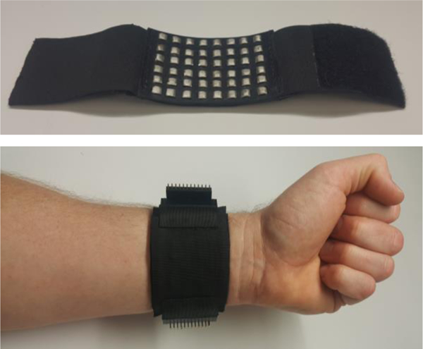
The bottom view of the wrist strap (top) and the strap worn on the wrist with the electrodes placed on the underside of the wrist (bottom).
Wrist-worn devices are the most common wearable medical devices because they are comfortable, can be worn as a watch, and allow integration of several physiological sensors. Several physiological signals can be measured from the wrist such as electrocardiography (ECG) [2], which can be used for heart rate detection, electro-dermal activity (EDA) for stress detection [3] and bio-impedance (Bio-Z) signals which can be used in plethysmography and pulse wave velocity estimation. In addition, electrical impedance tomography (EIT) can be applied on the wrist using a number of bioimpedance sensors that surround the wrist to reconstruct an image of the wrist, which can be used for applications such as gesture recognition [4].
There are several challenges in using wrist-worn devices for robust physiological sensing. one of these challenges is the proper placement of the electrodes each time the wrist device is worn [5]. For example, the features of the plethysmograph, which is a measure of the blood volume changes, become sharper as the sensor is placed very close to a major artery. There are significant physiological differences between different people, and in addition, there is no guarantee that the user will wear the device each time in exactly the same position; therefore placing a sensor at the optimal location becomes a challenge. The sensors can be placed correctly only by experts using advanced medical equipment, which presents a challenge when the device is expected to be operated outside clinics and by non-expert consumers. Motion artifacts are another challenge for wearable medical devices, referring to signal corruption that occurs when the subject moves during data acquisition [6]. One of the main reasons for the signal distortion is the temporary loss of contact between the electrode and the skin during the movement. Therefore, the ability to assure proper placement of the electrodes covering certain sensing sites and retaining good contact between the electrodes and the skin though incorporating redundancy and leveraging an array of electrodes appear to provide a suitable solution to the aforementioned challenges.
In this work, we propose a wrist strap with an array of high-density and miniature electrodes to obtain physiological signals across the 2-D area underneath the array with the ability to provide a local measurement across few millimeters at each electrode site on the wrist. This design enables capturing physiological signals with high spatial resolution both improving the robustness of sensing and enabling new sensing paradigms such as the ability to measure pulse transit time and pulse wave velocity using two pairs of electrodes for blood pressure monitoring [2, 7]. Our proposed design provides the ability to automatically select the right sensing location regardless of variations in the placement of the strap on the wrist. In addition, the 2-D array of sensors offers opportunities for spatial monitoring of physiological signals that has many applications [8]. In this paper, we present a wrist strap that includes a 2-D array of 48 electrodes. Each electrode has dimensions of 5×5 mm with a spacing of 3.2 mm between each of them, covering an area of 6.25×4.60 cm on the bottom face of the wrist with good skin contact. The array of electrodes provides high (re)configurability by allowing current injection or voltage sensing between any two points on this array. Regardless of how the user wears this device on the underside of the wrist, there will be an electrode that is placed very close to the target location, which can be detected by a searching technique that involves sweeping the electrodes and comparing the signals together to select the best-sensed signal. This search method can be done regularly to update the chosen electrodes if there is a change in the placement of the device on the wrist during operation. This array also helps reduce the effect of motion artifacts because quite likely, not all the electrodes would lose contact with the skin at the same time in presence of movements. If corrupted signals are detected from one electrode, the signal from the next nearest or another electrode, which likely has a stable contact, can be used. In addition, this array of electrodes has wide applications, such that it can measure any bio-potential or bio-impedance signal from the wrist such as ECG, Bio-Z, EDA, etc.
The contribution of this paper is summarized as follows:
A novel 2-D array of electrodes is presented for robust wrist physiological sensing that covers the wrist with miniature electrodes distributed on the wrist with a higher density to allow for automatic selection of the right sensing location regardless of the on-body placement.
The design of the strap that provides good contact with the skin for all of the electrodes of the array, which reduces the effect of motion artifacts by providing continuous contact with the skin for at least some subset of the electrodes when movements are present.
In this paper, we describe the design and implementation of the wrist strap, including the array of electrodes, and the measurement system used for the electrode-skin impedance monitoring. We also characterize the electrode-skin impedance with respect to frequency and compare it to other types of dry and wet electrodes. Finally, we present the variation of the impedance of the array’s different wrist locations at rest and during some wrist movements.
II. Methods
A. Wrist Strap Design
We designed a wrist strap to ensure that the array of electrodes maintain good contact with the skin, offer minimized discomfort, and conform to all other technical requirements such as electrode size.
The size of the electrodes is an important parameter in the design of the array. The small size increases the number of electrodes within a specific area and enhances the spatial resolution of the measurements. However, electrode-skin impedance increases as the size of the electrode decreases because of smaller contact area with the skin, which increases the impact of motion artifacts in presence of wrist movement. The size of the electrode was chosen to be 5 mm as a trade-off between the spatial resolution and the skin contact area. The electrode size required was not readily available off-the-shelf, and therefore, it was fabricated in our laboratory.
Stainless steel key stock with the dimensions 5×5 mm square by 0.25 m long was used to fabricate the electrodes. Stainless steel was chosen since it would not oxidize, is a good conductor, and is inexpensive. No surface coating was used to study the conductivity of stainless steel without changing its characteristics by coating. The square shape was selected to be similar to the available commercial dry electrode for comparison. Two dimensions of the key stock were already to the 5×5 mm specification. The height of 5 mm was accomplished by chopping the key stock into segments with a bandsaw. Each electrode’s height was sheared to 5 mm +/− 0.01 mm. The electrodes were then contoured on the side that would be facing the skin with a bench grinder. The purpose of the contour is to provide a smooth surface that comfortably contacts the skin. The side of the electrode opposite to the skin surface was then prepped for an electrical connection.
Stainless steel cannot be easily soldered to which presents electrical connection issues. The solution to this was to provide an electro-mechanical connection. A 3 mm deep hole was drilled using a 135 degree 1.70 mm drill bit into the electrical side of the electrode. A 4 mm long copper rivet with a 1.65 mm diameter was placed into the hole. The rivet was then struck with a hammer forcing it to undergo radial expansion. This expansion secured the copper rivet firmly against the stainless steel electrode. The head of the copper rivet provides an excellent soldering pad. Forty-eight electrodes were fabricated and used with the array.
A small spacing of 3.2 mm between the electrodes was chosen to increase the number of electrodes within a small area. The 48 electrodes were arranged as 6 electrodes in the axial direction to the wrist and 8 electrodes in the radial direction to cover an area of 6.25 × 4.60 cm on the wrist. This area was selected to fit within a small form factor wrist strap and still fully cover the bottom side of the wrist for most users.
To align the sets of electrodes together, two layers of neoprene sheets were used to provide structure. Neoprene was selected due to its rigidity and ability to conform to the wrist. The two sheets, one 1/16” and the other 1/32”, were cut to 52×80 mm and glued together with high-performance neoprene adhesive. Using measuring calipers, the array layout was carefully constructed and marked on the surface of the neoprene. Razors were then used to cut out each electrode slot. Electrodes were placed in each slot and glued into place using the high-performance neoprene adhesive. Each electrode protrudes from the skin contact side by 1.75 mm. The purpose protrusion feature is to allow for better skin surface contact when the neoprene structure is secured to the wrist.
Each electrode set was aligned to the axial direction of the wrist. To secure the array in place, two elastic knit bands, 6.5 cm each, were sewed onto the neoprene in the radial direction. A Velcro hook and loop were sewed onto opposite ends of the knit bands. Once the Velcro components were sewed on, the wrist strap was tested. The wrist strap was placed around multiple volunteers’ wrists to confirm a secure fit. During this time, electrode continuity with the skin was verified.
Two 24 pin connectors were glued to the outer side of the wrist strap and on opposite sides of the array from one another. 42 AWG insulated copper wire was soldered between the electrodes and the connector pins. All forty-eight of the electrodes were connected to a designated pin. Once this was complete, the electrical connections were covered up with another layer of 1/32” neoprene for protection. Resistance tests were then conducted to verify adequate conductivity between the electrodes and their pins.
B. Electrode-Skin Impedance Measurement System
The performance of the electrodes was characterized by the electrode-skin impedance, which was determined by applying AC current between an electrode pair placed on the wrist and measuring the voltage between them. The measured impedance is the result of electrode-skin impedance, which neglects the wrist tissue impedance since it is very small compared to the typical electrode-skin impedance [7].
In order to test the performance of the electrodes across a range of frequencies and in presence of wrist movements, a programmable hardware capable of accurate continuous-time monitoring of the real and imaginary components of the electrode-skin impedance at various frequencies for several seconds was used. Current with an amplitude of 150 uA was applied by a programmable current source built from a 16-bit digital to analog converter (DAC) followed by voltage to current converter as shown in Figure 2. The voltage was measured by a 24-bit ADC with a range of +/− 2.5 V. An ARM Cortex M4 micro-controller unit (MCU) was used to adjust the sampling rate of the system at 93.75 kSPS and to control the frequency of the AC current from 4 kHz to 20 kHz. The ADC output and the waveform generated by the MCU was sent to the PC through USB for signal post-processing in MATLAB. The ADC output was filtered using a 2nd order band pass filter (BPF) centered at the AC current frequency to remove the DC, interference and high-frequency components. Quadrature demodulation was used to generate the real R(Z) and imaginary I(Z) components of the impedance by multiplying the ADC signal by the waveform generated from the MCU and its 90-degree phase shift followed by a low-pass filtering at 4.4 Hz to remove high-frequency noise. For accurate impedance measurement, reference resistors with known values were used to measure the gain and phase errors of the system versus frequency, which were calibrated for the actual measurements.
Figure 2.
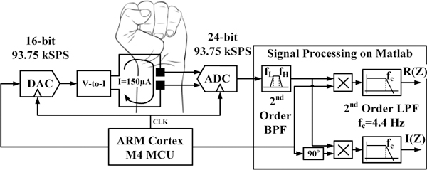
The block diagram of the electrode-skin contact impedance measurement system.
III. Experiments and Results
In the first set of experiments, we compared the electrodeskin impedance of our electrode array against two types of commercial dry electrodes and the conventional wet electrode, which are shown in Figure 3. All experiments were approved by the institutional review board (IRB) at the Texas A&M University. The first type of dry electrode was from a UP3 Jawbone® wearable device, which is a commercial wrist-worn heart rate tracker that uses wrist bio-impedance monitoring. The shape and size of this electrode are similar to our electrode and both are comfortable for the user. However, the Jawbone® electrode should have lower impedance because it is externally coated with a highly conductive material to reduce the electrode-skin impedance. The second type of a commercial dry electrode was an 8 mm diameter disc of sintered Ag/AgCl, which is a good conductive material. The wet electrode used was a Covidien Ag/AgCI pre-gelled adhesive electrode with 24 mm diameter. The Ag/AgCI and adhesive gel with its large area provides the best conductivity among all types of electrodes, but it is not suitable for continuous wear because it prevents skin from breathing. The electrode-skin impedance was measured between the four electrode pair types by injecting a current of 150 uA in the range of 4 kHz to 20 kHz, in steps of 4 kHz. Each pair was placed at approximately a distance of 4.5 cm at the same location on the human subject’s wrist. The electrode-skin impedance versus frequency for the four types of electrodes can be seen in Figure 4.
Figure 3.
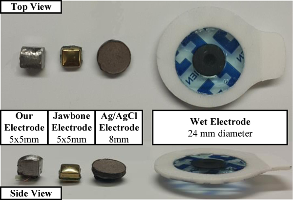
The top and side views of our electrode compared to the other types of electrodes.
Figure 4.
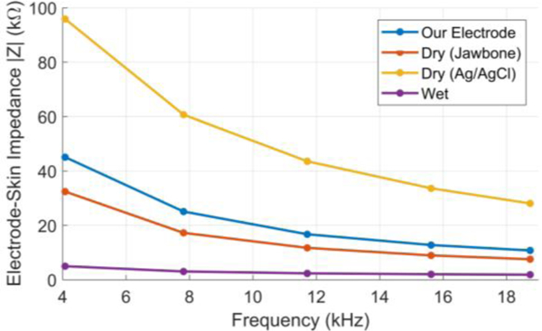
The electrode-skin impedance versus frequency for the four types of electrode used in the experiment.
As the frequency increases, the impedance decreases, likely due to the reactance. Reactance is believed to be caused by the skin’s response to an alternating current due to its capacitive nature. Skin is usually modeled as an equivalent circuit containing a capacitor and resistor in parallel [9]. The graph shows that the wrist array has about a 40kΏ greater impedance at low frequency and a 10 kΏ greater impedance at a higher frequency than the wet electrode pair, which was expected. It was also noted that the Jawbone electrode has slightly lower impedance than our electrode because of its external coating. However, the dry Ag/AgCl electrode has the highest impedance among all types despite of its high conductivity. This can be explained by the concave shape of the surface of this dry Ag/AgCl electrode which decreased the skin contact area. This indicates the importance of the protrusion of the electrode surface to decrease the electrode-skin impedance as implemented in our electrode. Figure 5 displays the electrodeskin reactance, which correlates directly with Figure 4. These results show that our metal electrode has low electrode-skin impedance compared to the other dry electrodes and follow the same frequency trend.
Figure 5.
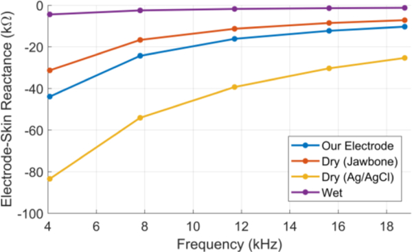
The electrode-skin reactance versus frequency for the four types of electrode used in the experiment.
In the second set of experiments, the performance of the electrode array in terms of the electrode-skin impedance was characterized in the spatial domain by segmenting the electrodes into twelve sections, three rows, and four columns, as seen in Figure 6. Each section is labeled as (i,j), where i is the row index from 1 to 3 and j is the column index from 1 to 4. The purpose of this division is to gain insight about electrode-skin impedance for each section of the array.
Figure 6.
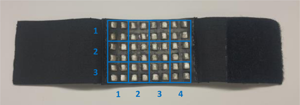
The subsections of the array of electrodes used to monitor the variations of the electrode-skin impedance in the spatial domain.
A current of 150 uA at 16 kHz was injected through electrode pairs corresponding to each section for 10 seconds. The frequency of 16 kHz was selected since it showed small electrode-skin in our previous experiment. During this time, the wrist was kept stationary. The electrode-skin impedance for each section was calculated and averaged within 10 seconds of measurement. The measured impedances for all sections were in the range of 5–9.6 kΏ as presented in Figure 7. These small values of impedance at the normal wrist position for all locations demonstrates the good conformity of the strap to the wrist that provides good skin contact for all electrodes in the array.
Figure 7.
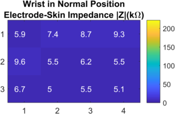
The wrist array impedance in the spatial domain at twelve different locations on the wrist at normal wrist position.
The electrode-skin impedance values varied slightly across different sections and they correlate directly with the pressure gradient resulting from the wrist strap’s pressure distribution onto each of the electrodes. Once the array was removed, we noted that the impressions on the skin due to the electrodes were lighter in areas of higher impedance and more profound in areas of low impedance. We hypothesize that the cause of decreased impedance was not due to an increased pressure between the electrode and skin. Instead, the impedance electr across the array was more likely due to the electrode’s surface contact with the skin. Since more pressure can cause the skin to surround the protruding electrodes, it is determined that this increased the surface contact with the skin, thus decreasing the impedance. This hypothesis is supported by the fact that impedance is attributed mainly to the acellular outer layer of the skin [10].
In the third set of experiments, we evaluated the electrodeskin impedance for twelve sections of the array in presence of wrist motion. During each test sequence, the wrist started from the normal position, then bent away from the body for two seconds and towards the body for another two seconds, and then finally it returned back to its normal position. The wrist movement was expected to change the impedance due to the alteration of skin continuity due to the movements. Figure 8 shows three examples of the variation in impedance with time due to wrist movement at three different locations. First, the section (1,4) showed from t=2 to t=4 seconds significant increase in the impedance up to 70.5 kΏ with inwards bending, while no change occurred during outwards bending. The opposite occurred in section (1,1) where impedance increased from t=5 to t=7 second to 170 kΏ during outwards bending only. On the other hand, section (2,4) showed very small changes during both movements.
Figure 8.
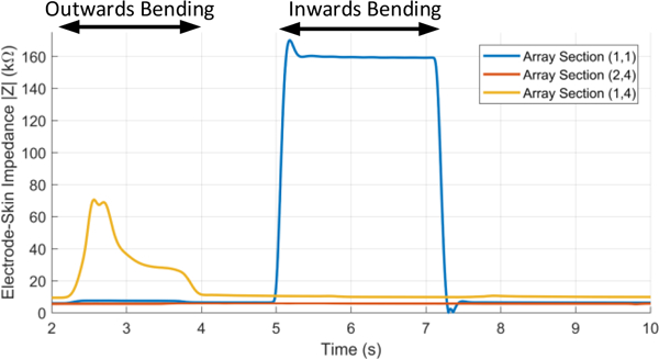
Examples of the electrode-skin impedance changes with time at several wrist locations during the wrist movement.
Figure 9 shows the twelve locations and their respective impedance values at each wrist location for both outwards and inwards bending of the wrist. For outwards bending, all locations showed good contact with the skin with impedance values below 20.6 kΏ except for one section (1,4) which was 70.5 kΏ. For inwards bending, the effect of bending was more prominent where four sections exhibited high impedance larger than 170 kΏ, which indicated decreased contact with the skin at these locations.
Figure 9.
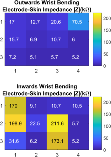
The wrist array impedance in the spatial domain at twelve different locations on the wrist when the wrist was bent outwards (top) and bent inwards (bottom).
These results show that the quality of electrode contact with the skin during wrist movement varies with the location on the wrist, which depends on several factors such as the user’s wrist shape, the type of movement, and the position of the wrist strap. Therefore, using an array of electrodes provides a persistent contact with the skin at any time through at least a subset of electrodes, which allows detecting the locations that remain unaffected by the wrist movements, hence improving the robustness of the physiological sensing from the wrist.
IV. Conclusion
A novel wrist strap with an array of electrodes was presented for robust physiological sensing. The 2-D array of electrodes covers a good portion of the wrist, provides suitable contact with the skin and allows localized measurements at each electrode site, which enables selecting the best set of electrodes for signal monitoring regardless of the placement of the wrist strap on the wrist. In addition, sensing at different locations on the wrist can reduce the effect of motion artifacts because certain locations are less impacted by specific wrist movements. Our electrodes showed low electrode-skin impedance compared to other dry electrodes, while our proposed design provides a comfortable wearing experience and offers spatial sensing coverage. The variation of electrodeskin impedance in the spatial domain was shown during wrist movement, which showed continuous skin contact at certain locations on the array. This array of electrodes can improve the robustness of physiological sensing with wrist-worn devices, which could enhance the deployment of wearable medical devices by the general population.
Footnotes
Human subject testing was conducted at Texas A&M University under IRB approval IRB2017–0086D and informed consent was acquired from all participants.
Contributor Information
Bassem Ibrahim, Department of Electrical and Computer Engineering at Texas A&M University, College Station, Texas, 77843, USA..
Justin McMurray, Department of Biomedical Engineering at Texas A&M University, College Station, Texas, 77843, USA..
Roozbeh Jafari, Departments of Biomedical, Computer Science and Engineering, and Electrical Engineering at Texas A&M University, College Station, Texas, 77843, USA..
References
- [1].Rodgers MM, Pai VM, and Conroy RS, “Recent Advances in Wearable Sensors for Health Monitoring,” IEEE Sensors Journal, vol. 15, no. 6, pp. 3119–3126, 2015. [Google Scholar]
- [2].Thomas SS, Nathan V, Zong C, Soundarapandian K, Shi X, and Jafari R, “BioWatch: A noninvasive wrist-based blood pressure monitor that incorporates training techniques for posture and subject variability,” IEEE journal of biomedical and health informatics, vol. 20, no. 5, pp. 1291–1300, 2016. [DOI] [PubMed] [Google Scholar]
- [3].Garbarino M, Lai M, Tognetti S, Picard R, and Bender D, “Empatica E3 - A wearable wireless multi-sensor device for real-time computerized biofeedback and data acquisition,” 2014. [Google Scholar]
- [4].Zhang Y, Xiao R, and Harrison C, “Advancing hand gesture recognition with high resolution electrical impedance tomography,” in Proceedings of the 29th Annual Symposium on User Interface Software and Technology, 2016, pp. 843–850: ACM. [Google Scholar]
- [5].Pantelopoulos A and Bourbakis NG, “A Survey on Wearable Sensor-Based Systems for Health Monitoring and Prognosis,” IEEE Transactions on Systems, Man, and Cybernetics, Part C (Applications and Reviews), vol. 40, no. 1, pp. 1–12, 2010. [Google Scholar]
- [6].Majumder S, Mondal T, and Deen MJ, “Wearable Sensors for Remote Health Monitoring,” Sensors (Basel), vol. 17, no. 1, January 12 2017. [DOI] [PMC free article] [PubMed] [Google Scholar]
- [7].Ibrahim B, Jafari R, and Akbari A, “A Novel Method for Pulse Transit Time Estimation Using Wrist Bio-Impedance Sensing Based on a Regression Model,” 2017 IEEE Biomedical Circuits and Systems (BioCAS), 2017. [Google Scholar]
- [8].Zheng YL et al. , “Unobtrusive sensing and wearable devices for health informatics,” IEEE Trans Biomed Eng, vol. 61, no. 5, pp. 1538–54, May 2014. [DOI] [PMC free article] [PubMed] [Google Scholar]
- [9].Bjorklund S et al. , “Skin membrane electrical impedance properties under the influence of a varying water gradient,” Biophysical journal, vol. 104, no. 12, pp. 2639–2650, 2013. [DOI] [PMC free article] [PubMed] [Google Scholar]
- [10].Nguyen D et al. , “Electrode-Skin contact impedance: In vivo measurements on an ovine model,” in Journal of Physics: Conference Series, 2013, vol. 434, no. 1, p. 012023: IOP Publishing. [Google Scholar]


