

Abstract
Soft and conductive nanomaterials like carbon nanotubes, graphene, and nanowire scaffolds have expanded the family of ultraflexible microelectrodes that can bend and flex with the natural movement of the brain, reduce the inflammatory response, and improve the stability of long-term neural recordings. However, current methods to implant these highly flexible electrodes rely on temporary stiffening agents that temporarily increase the electrode size and stiffness thus aggravating neural damage during implantation, which can lead to cell loss and glial activation that persists even after the stiffening agents are removed or dissolve. A method to deliver thin, ultraflexible electrodes deep into neural tissue without increasing the stiffness or size of the electrodes will enable minimally invasive electrical recordings from within the brain. Here we show that specially designed microfluidic devices can apply a tension force to ultraflexible electrodes that prevents buckling without increasing the thickness or stiffness of the electrode during implantation. Additionally, these “fluidic microdrives” allow us to precisely actuate the electrode position with micron-scale accuracy. To demonstrate the efficacy of our fluidic microdrives, we used them to actuate highly flexible carbon nanotube fiber (CNTf) microelectrodes for electrophysiology. We used this approach in three proof-of-concept experiments. First, we recorded compound action potentials in a soft model organism, the small cnidarian Hydra. Second, we targeted electrodes precisely to the thalamic reticular nucleus in brain slices and recorded spontaneous and optogenetically evoked extracellular action potentials. Finally, we inserted electrodes more than 4 mm deep into the brain of rats and detected spontaneous individual unit activity in both cortical and subcortical regions. Compared to syringe injection, fluidic microdrives do not penetrate the brain and prevent changes in intracranial pressure by diverting fluid away from the implantation site during insertion and actuation. Overall, the fluidic microdrive technology provides a robust new method to implant and actuate ultraflexible neural electrodes.
Keywords: Flexible microelectrodes, neural interfaces, neurophysiology, carbon nanotube fibers, microfluidics
Graphical Abstract
Chronically implanting electrodes enables measurements of the spiking activity of individual neurons in freely behaving animals, which illuminate the neural processes underlying learning, movement, perception, and cognition in healthy and diseased states. Over the past few years these chronically implanted microelectrodes have led to breakthrough discoveries and technological innovations, including control of robotic end effectors,1,2 restoration of the cortical control of the upper limbs,3 discovery of fundamental mechanisms underlying cognitive processes,4,5 and identification of unique neural firing patterns associated with epileptic activity.6–8
Despite their foundational role in systems neuroscience and brain-machine interfaces, existing microelectrode technologies have significant challenges. Electrodes have traditionally been manufactured using metals or micromachined silicon. The ~108-fold stiffness mismatch between the electrode material and the soft host brain tissue causes acute and chronic injury that results in extensive neuronal death, formation of gliotic encapsulation and isolation of the recording sites from the neuronal bodies.9,10 Moreover, relative micromotion between the tissue and the implant can exacerbate the strain-induced inflammatory reaction and cause the recording site to drift from its original position.11,12 Thus, creating electrodes from highly flexible materials holds great promise for improving the electrode–brain interface.13–18
In the past decade, several advances in the synthesis and characterization of several families of nanoscale building blocks, including nanoparticles, nanotubes, nanorods, two-dimensional nanosheets, and the recognition of unique structure–property relationships distinct from their bulk counterparts, have led to new classes of ultraflexible neural electrodes.19–22 Nanoscale carbon allotropes, in particular, have attracted increasing attention due to their unique combination of electrical conductivity,23,24 mass-specific surface area,25,26 high mechanical strength,27,28 magnetic resonance safety,29,30 and chemical stability.31 Recent works have demonstrated thin film, graphene-based optoelectronic interfaces for simultaneous imaging and electrophysiology,32,33 and the potential of reduced graphene oxide and carbon nanotubes for improving impedance and charge delivery characteristics of soft, freestanding neural implants.34–40
Recently, we demonstrated that soft, high-performance CNTf microelectrodes fabricated from wet-spinning of a liquid crystalline dispersion of CNT in chlorosulfonic acid41 have ~8 times lower area-normalized interface impedance than carbon fibers (CNTf 17.44 MΩ μm2, carbon fibers13 144.09 MΩ μm2) and are effective for neuromodulation and chronic recording applications, while eliciting minimal foreign body reaction when compared to metal implants.42
The major drawback of these novel compliant materials lies in the surgical implantation: when the unsupported length of the electrodes is longer than a critical limit (typically order 1–2 mm for state of the art electrodes)43,44 they buckle rather than enter the brain tissue. This challenge has been solved by temporarily increasing the stiffness of the electrode.45 For example, flexible electrodes can be stiffened through attachment to a rigid probe during insertion16,42,46 or by overcoating with a hydrogel sheath47–49 that dissolves minutes after implantation. However, the increased rigidity and footprint of the stiffener–electrode assembly can aggravate the acute and chronic injury, damaging or destroying nearby neurons and breaching the blood brain barrier.42,50,51 Recent works17,52 demonstrated that macroporous three-dimensional (3D) mesh electrodes with cellular-scale feature sizes (~20 μm) and mechanical flexibility 107 times greater than conventional silicon greatly improve the integration of neural electrodes with brain tissue and are capable of intraoperative and chronic recordings in vivo. However, to implant these devices a rigid syringe with a diameter of 650 μm must be inserted into the cortex17,52,53
A new technology to insert and precisely position flexible, cellular-scale electrodes without temporary stiffening would significantly improve the robustness and utility of flexible electrodes while minimizing excess damage to the brain from stiffeners. To reach this goal, we developed a novel strategy to implant and microactuate flexible microelectrodes without using external supports or stiffening agents. Instead, we use viscous fluid flow in a microfluidic channel to maintain tension in the electrode structure, effectively stiffening it without increasing the implant footprint. Using microfluidic vent channels, we can then divert nearly all the fluid away from the point of electrode insertion. The result is a fluidic microdrive technology which enables the accurately controlled insertion of flexible electrodes. As a proof-of-concept, we demonstrate electrophysiological recordings from ultraflexible cellular-scale electrodes following fluidic implantation into small organisms, acute mouse brain slices, and the brain of anesthetized rats.
Cellular-scale CNTf microwires are promising neural electrodes for stimulation and recording42 whose flexibility presents a significant challenge for neural implantation. For this study, we used CNTf microwires with diameter between 12 and 25 μm insulated with either a conformal bilayer of 50 nm Al2O3 and 25 nm of HfO254 or 1.2 to 3.3 μm of parylene C (Supporting Information (SI) Figure S1). After the insulation step, we measured the bending stiffness of the parylene-coated CNTf microelectrodes to be 0.23 × 10⁻⁹ Nm2 for the 12 μm diameter probes (postinsulation diameter 18.3 ± 0.7 μm, mean ± s.d., n = 3) and 1.08 × 10⁻⁹ Nm2 for the 25 μm diameter probes (postinsulation diameter 28.9 ± 0.6 μm, n = 3), which is comparable to the flexibility of polyimide probes that have been shown to require stiffening supports for successful surgical implantation55 (SI Figure S3). As the penetration of water and ions through the insulating coatings is one of the major causes leading to the failure of chronic neural implants and it is still an active area of investigation,56,57 we performed leakage current and impedance spectroscopy measurements before and after 90° bending the parylene-coated CNTf prior to exposing the electrode recording site and found no evidence of acute breakdown of the insulating layer (SI Figure S2). To expose the conductive CNTf core at the ends of the electrode, we cut the electrode using a razor blade or focused ion beam (FIB).
We fabricated microfluidic microdrives from two layers of polydimethylsiloxane (PDMS) using conventional replicamolding techniques.58 As shown in Figure 1, fluid flows through the channel containing the electrode but is diverted away from the implantation site to minimize tissue damage. We manually placed CNTf microelectrodes in the center of the channel before plasma bonding the channels to a glass substrate. After the PDMS device was bonded, plastic tubing was plugged into the flow ports that connect the device to the flow control system.
Figure 1.
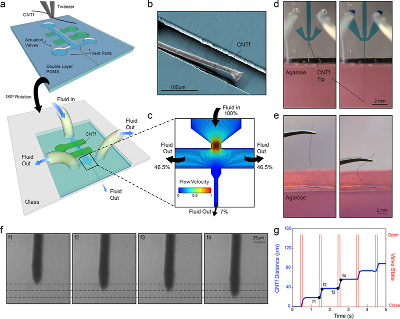
Device layout and microfluidic-assisted insertion of flexible CNTf microelectrodes in vitro. (a) Schematic of the two-layer PDMS microfluidic device. Microelectrodes are placed and aligned manually inside the channel (top). The device is then inverted and bonded to a glass substrate (bottom). Push-down actuation valves (green) provide on-chip flow control. (b) False-colored SEM image of a 12 μm diameter microelectrode inside the PDMS channel. (c) Velocity field and flow pathlines in the microfluidic device. More than 93% of the total volume of fluid injected is deviated to the side venting ports, which minimizes the amount of fluid delivered to the outlet channel. (d) Microfluidic-assisted insertion of 12 μm microelectrode in a brain phantom: the drag force produced by the fluid drives the fiber 4.5 mm into the phantom without evidence of bending. When mechanical insertion is attempted (e), the microelectrode irreversibly buckles upon contact with the agarose surface and does not penetrate inside the phantom. (f) Microscope images of the microelectrode position in an agar tissue phantom at times corresponding to panel g. Dashed lines, spaced approximately 15 μm, indicate the position of the fiber end. (g) Stepwise electrode insertion (blue trace) is controlled by opening the flow control valve for 100 ms intervals (red trace). The average fiber displacement during the open valve period is 16.4 ± 6.4 μm (mean ± s.d., n = 43 steps, 2 trials). Positions labeled f1–f4 refer to the images shown in panel f.
The liquid flowing in the microfluidic channel exerts a viscous drag force on the microelectrode due to the velocity differential that distributes the force applied to the fiber and holds it under tension. Finite element simulations show that the force at which the CNTf electrode buckles (the critical buckling load) increases by approximately 3 times when the load is distributed along the probe rather than applied to a fixed point near the rear of the electrode. Thus, compared to traditional insertion strategies that concentrate the load on a single point, we expect that our microfluidic devices will allow us to apply more force to the electrodes without causing buckling. Because this increase in the critical buckling force is the result of distributing the load, the enhancement factor is independent of the electrode material. Changes to the load distribution profile could further increase the critical buckling load. For example, if the profile of the distributed load is no longer homogeneous but instead increases linearly or quadratically along the probe length, we expect an increase in the critical buckling force by a factor between 16 and 30.59
We first tested our microdrive using an agarose brain phantom. The combined effect of the tension on the fiber and the confinement in the microfluidic channel allowed us to drive a parylene-coated 12 μm diameter CNTf more than 4.5 mm deep into a brain phantom, (Figure 1d, SI Video M1). In contrast, all of our attempts (n = 4 fibers) to implant 12 μm diameter CNTfs without the fluidic microdrive resulted in buckling upon contact with the phantom surface (Figure 1e, SI Video M2). This buckling was observed despite using manually actuated translation stages to guide straight and vertical entry into the phantom.
A major advantage of our fluidic microdrives compared to traditional syringe injection is the fact that we can minimize the volume of fluid injected into the brain and thereby reduce any risk of overpressure that could produce trauma to the brain tissue. By creating a large hydraulic resistance through the exit channel, we can divert the fluid flow into microfluidic vent channels that safely transport the fluid away from the injection site. Because the hydraulic resistance depends inversely as the third power of the channel cross sectional area,60,61 we created three main sections of our device where we adjusted the channel width to control the fluidic resistances: a wide, low-resistance upstream channel connected to the flow input port converging into a high-resistance outlet channel for micro-electrode delivery and two low-resistance side ports. Details on the two channel geometries used in this work are reported in Supporting Information (SI Figure S10).
Computational analysis of the flow field in the device (Figure 1 b) shows that the area of maximum flow velocity is concentrated in the converging nozzle and that the venting ports divert more than 93% of the input volume with the remainder of the fluid flowing downstream to the exit channel. Note that these relative fluid flow rates are computed in the absence of the electrode. With an electrode blocking much of the exit channel we expect the fluidic resistance to be higher and even less fluid to be ejected with the electrode.
The hydraulic design and the control of the on-chip valves enable actuation and positioning of the CNTf. In the microfluidic channel, we can control the fiber velocity and direction by controlling the fluid flow rate. As expected, larger flow rates corresponded to more rapid microelectrode motion (SI Figure S5 and Video M3). Targeting of specific brain regions often requires insertion of electrodes to a defined depth. Moreover, recording individual neurons in vivo often requires even more precise control to place microelectrodes into the proximity of neuronal cell body. Thus, we explored the ability to microactuate the electrode using on-chip actuation valves. In an agar tissue phantom, we observed that opening the microfluidic actuation valves at 100 ms intervals allowed us to reliably advance a CNTf with 25 μm in diameter with a step size of 16.4 ± 6.4 μm (n = 43 steps, two trials, Figure 1f,g).
As an example of the fluidic microdrive implementation, we performed electrophysiological measurements in the freshwater cnidarian Hydra (H. littoralis). Hydra are a compelling model organism because they are easily cultured in the laboratory and are known to generate compound action potentials that correspond to body contractions (contraction bursts, CBs)62 but their soft, deformable body makes them exceedingly challenging for conventional electrophysiology. To interrogate Hydra, we modified our microfluidic system to control the position of the animal body. In our experimental setup depicted in Figure 2a, the working Ag/AgCl electrode is connected to the microfluidic device and makes electrical contact to a microelectrode with 12 μm in diameter through the conductive drive solution (dextran in PBS, 40% w/w) filling the channels, yielding a final impedance of 663.7 ± 127.0 kΩ (mean ± s.d., n = 3 devices). Throughout the experiment, we held the Hydra approximately 3 mm downstream from the microdrive exit channel by applying moderate negative pressure to trap channels located in a separate PDMS block (Figure 2b). The pressure applied by these channels was sufficient to prevent the animal from moving along the chamber but allowed the Hydra to contract, elongate, and nod. It is worth noting that despite the low levels of negative pressure used for trapping, we observed that some of the Hydra tissue was dissociated and pulled through the trapping channels. While this damage did not prevent stereotypical contractions and elongations during roughly 1 h of immobilization, improved immobilization chambers may be necessary for longer experiments.
Figure 2.
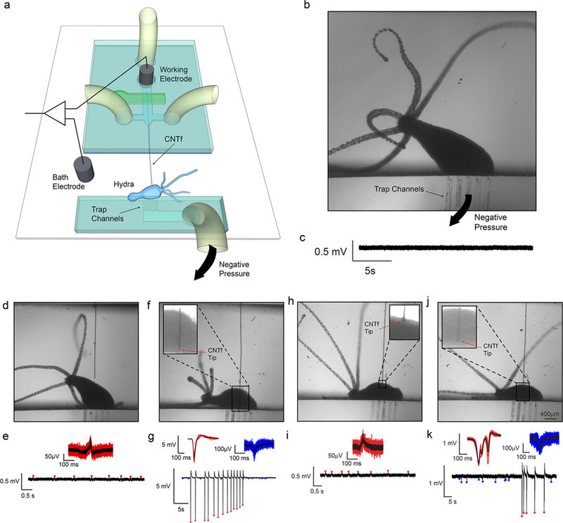
In vivo electrophysiology in Hydra (n = 3 animals). (a) Schematics of Hydra recording chamber. The reference electrode was placed in the bath while the working electrode was inserted into the microfluidic channel, making electrical contact with the CNTf microelectrode through the conductive Dextran solution. Hydra was secured ~3 mm away from the microelectrode exit. (b) Optical microscope image shows Hydra trapped in the device by gentle negative pressure applied to the trap channels. (c) No peaks were observed when the microelectrode was more than 1 mm away from Hydra even during body contractions. (d,e) Microelectrode located next to Hydra recorded small amplitude peaks (red) during body contractions only. (f,g) Microelectrode inserted in Hydra recorded high amplitude peaks (red) during body contraction and small amplitude peaks (blue) in the absence of body contractions. (h,i) Microelectrode was retracted to a position near the Hydra body. Small peaks were recorded only during body contractions similar to (e). (j,k) The microelectrode was reinserted in the animal where we could once again record large peaks during body contractions (red) and small peaks in the absence of body contractions (blue) similar to panel (g).
By controlling the fluid flow and the on-chip valve actuation system, we were able to bring the microelectrode into contact with Hydra (n = 3 animals) and record compound action potentials. When the CNTf microelectrode was retracted into the fluidic device we recorded no electrophysiological activity even during body contractions (Figure 2c); however, when we used the microfluidic device to position the microelectrode approximately 50 μm from the Hydra body, we detected small-amplitude spikes (~120 μV) that corresponded to body contractions (Figure 2d,e and SI Video M4). No activity was observed during body elongation and nodding. Next, we inserted the microelectrode into the Hydra and recorded spikes with much larger amplitudes (4.5–6 mV, Figure 2f,g) correlated with body contractions. These large-amplitude spikes (a.k.a. contraction bursts, CB) are believed to originate from a nerve ring located at the junction of the tentacles and the body column. CBs correspond to synchronous neural and muscular activity, and the electrical recordings are likely a summation of this activity.63 These spikes are consistent with previously reported CBs,64 confirming that our fluidic-actuated CNTf microelectrodes act as microactuated flexible electrodes for electrophysiological recordings. In addition to large amplitude spikes, we also recorded low-amplitude spikes (50–150 –V, Figure 2g) that did not correlate with body contractions. These low-amplitude potentials are likely due to other behaviors such as elongation or tentacle contractions, which are known to correspond to small-amplitude spikes.64 It is worth noting that in previous studies, CBs were recorded with amplitudes of ~200 mV. These recordings were obtained using suction electrodes that seal the animal against a glass pipet,64 which greatly reduces the leakage current and increases signal amplitude. Recordings from implanted CNTf microelectrodes in Hydra are more similar to extracellular recordings in the brain, where no seal is formed, resulting in CBs with lower amplitude.
To illustrate our ability to precisely position the CNTf microelectrodes to record from different areas we used our fluidic microdrive to retract and reinsert the microelectrode. When we retracted the microelectrode, we once again recorded low-amplitude peaks correlated with contractions (Figure 2h,i). After reinsertion, we recorded high-amplitude signals correlated with contractions together with the low-amplitude activity (Figure 2k) independent from contraction. We noted, however, a change in the waveform of the contraction peaks. This variation in the waveform is likely due to a difference in the Hydra position, which agrees with previous reports that recorded CB waveforms depend on the position of the electrode with respect to the animal body.64
Electrophysiology ex vivo in acute sections taken from the mammalian brain using manually positioned glass pipet microelectrodes is a well-established experimental technique. To demonstrate that our fluidic microdrives can also place ultraflexible electrodes at specific locations within a mammalian brain, we recorded neural activity in thalamocortical brain slices of mice (13–21 days old). The ex vivo slice provides the distinct advantage of allowing for the electrode position to be precisely visualized during the experiment, enabling assessment of the placement accuracy of our fluidic actuation technology. To minimize damage to the neural tissue, we etched the ends of 25 μm in diameter CNTf microelectrodes to create a sharp tip (30°) using a FIB mill (SI Figure S6). Using our fluidic microdrives, we successfully inserted microelectrodes into cortex (up to ~1 mm deep, Figure 3a,d) and into specific thalamic nuclei (~4 mm from the cortical surface, Figure 3a,e).
Figure 3.
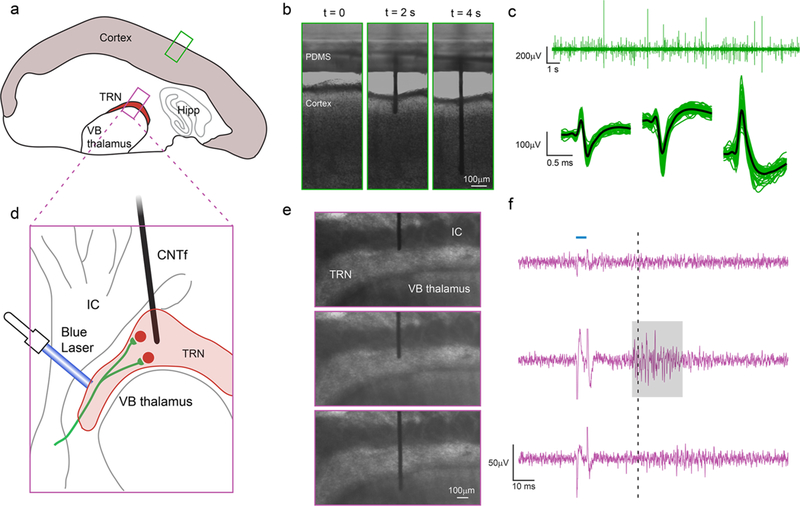
Microfluidic actuation and interrogation of CNS neural circuits in brain slices. (a) Schematic of thalamocortical section of a mouse brain depicting the two regions interrogated: cortex and thalamic reticular nucleus (TRN). (b) Sequence of CNTf microelectrode insertion into neocortex. (c) Cortical activity recorded by the microelectrode in cortex (n = 3 slices, one slice per animal) (top). Automatic detection algorithms isolated action potentials from individual neurons, shown temporally aligned and averaged (bottom). (d) Schematic showing ChR2 expressing cholinergic synaptic afferents in ChAT–ChR2–EYFP mouse line (green) targeting TRN but not the adjacent ventrobasal (VB) thalamus or internal capsule (IC). (e,f) Stimulation of cholinergic afferents with (5 ms) single laser pulses (blue horizontal line, F, top) triggers action potential activity specifically in TRN neurons. Spikes in the voltage recording during the optical stimulus (f) is an artifact produced by illuminating the microelectrode. When the microelectrode was positioned immediately above the TRN (e, top) no laser-evoked activity was recorded (f, top). Once the microelectrode was positioned within the TRN (e, middle), we recorded laser-evoked responses (highlighted by gray area) approximately 30 ms (dashed line) after stimulation. By inserting the microelectrode further, we could position the electrode in the VB thalamus (e, bottom), where no laser-evoked activity was detected (f, bottom), indicating that neuronal activity was acquired only from regions close to the tip of the microelectrode. Recordings in cortex (b,c) and TRN (e,f) were obtained from slices from wild-type and transgenic mice, respectively.
Following microelectrode insertion into cortex (Figure 3b) of brain slices extracted from wild type mice (n = 3 slices, one slice per animal), we were able to detect spontaneous neuronal activity as extracellular action potentials (Figure 3c, top). Our automated spike detection and clustering algorithm isolated spikes with amplitudes around 50–500 μV (Figure 3c, bottom).
Taking advantage of the possibility to precisely position the microelectrode with the fluidic microdrive, we moved the microelectrodes to record spatially confined neuronal activity in the thalamic reticular nucleus (TRN) of brain slices from transgenic mice. The TRN is a shell-like structure that in our slice preparation had a thickness of 168 ± 62 μm (n = 4 slices). Neurons in the TRN are the target of cholinergic synaptic afferents from the basal forebrain and the brainstem. Previous studies have shown that stimulation of these afferents leads to the fast and reliable activation of both nicotinic and muscarinic acetylcholine receptors (nAChRs and mAChRs)65 and the generation of short-latency action potentials specifically in TRN neurons but not in neighboring thalamic nuclei.65 To selectively activate cholinergic afferents using optogenetics, we used brain slices obtained from ChAT–ChR2–EYFP transgenic mice (Figure 3 d), which express channelrhodopsin-2 (ChR2) specifically in cholinergic neurons.
When we positioned the microelectrode at the TRN/internal capsule (IC) boundary (Figure 3e, top), we did not detect neuronal activity in response to optical stimulation (Figure 3f, top). By opening the microfluidic flow control valves for 100 ms intervals, we then gently pushed the microelectrode into the TRN (Figure 3e, middle). In this region, we observed action potential activity approximately 30 ms following laser stimulation (Figure 3f, middle). Because neurons in the TRN do not express ChR2, the activity recorded in this region is the result of a postsynaptic response, and ~30 ms latency is in accordance with the literature.66 Finally, we pushed the microelectrode deeper into the ventrobasal (VB) thalamus below the TRN (Figure 3e, bottom). In this configuration, no responses were recorded by the electrode (Figure 3f, bottom), indicating that electrical activity was only detected by the microelectrode tip. To confirm that laser-evoked activity in the TRN was evoked by the activation of postsynaptic nAChRs, we bath-applied the specific nAChR antagonist dihydro-β-eryth-roidine hydrobromide (DHβE), which completely eliminated TRN activity (SI Figure S8). Taken together, these experiments show that our platform can not only insert bare flexible electrodes into the cortex but can also drive these electrodes deep within the mammalian brain and accurately position them in specific brain region.
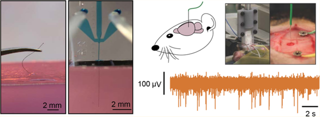
Next, we sought to demonstrate that the fluidic microdrive can be applied to in vivo rodent experiments. Using the microfluidic device, we successfully implanted flexible (12 μm diameter n = 3 animals, and 22 μm n = 3 animals) CNTf microelectrodes to a maximum depth of approximately 4 mm (12 μm diameter, 3.75, 3.39, and 4.17 mm; 22 μm diameter, 4.13, 4.27, and 4.10 mm) into the brain of anesthetized rats (Figure 4a,b, and SI Video M5). Currently, the maximum insertion depth is limited by the total length of the microfluidic channel, which is 10 mm for the devices we used in vivo. By using longer microelectrodes and longer flow channels, the drag forces can be increased and we expect to be able to drive CNTfs to even deeper regions in vivo.
Figure 4.
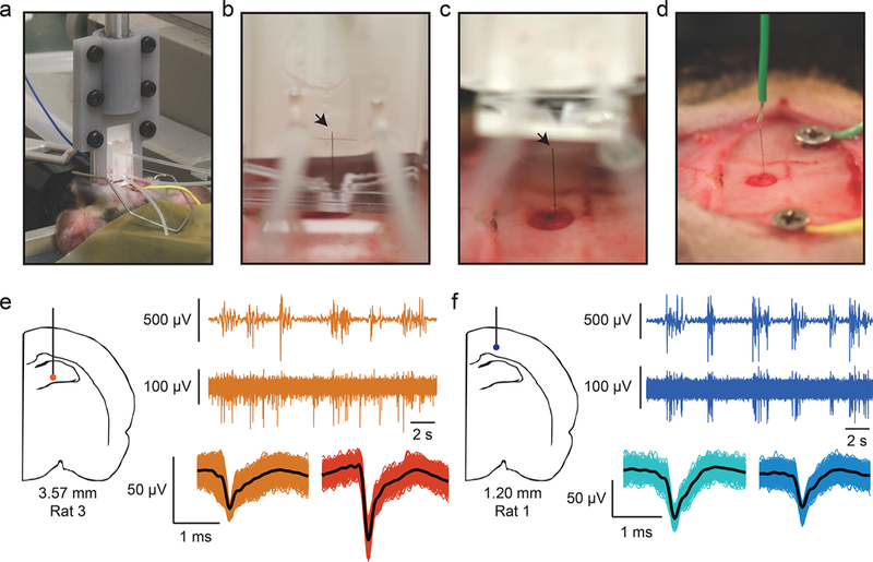
CNTf microelectrode recordings in anesthetized rats. (a) Photograph shows our microdrive attached to the stereotaxic arm using a 3D printed holder and positioned on top of the animal head. The device is gently placed in contact with the cortical surface through the craniotomy by actuating the stereotaxic arm. (b) Photograph of microelectrode following fluidic insertion into a rat brain. (c) To make electrical contact, the fluidic drive is retracted and (d) silver paint used to connect the microelectrode to a wire. Arrowheads mark the back end of the microelectrode. Note that (b–d) show a 22 μm diameter microelectrode for ease of visualization. (e,f) A representative example of 12 μm diameter microelectrode recordings at two depths from two different rats. (e) Orange traces are collected from 3.57 mm ventral, and (f) blue traces are from 1.20 mm ventral (as measured from the cortical surface). In each color, the top trace represents EEG signal collected from a screw placed over right frontal cortex. The burst-suppression pattern visible in the EEG is typical of isoflurane anesthesia. The bottom trace shows spikes recorded from the microelectrode and clustered spikes are shown below that. Note that at 3.57 mm from cortex, spikes are not well timed to EEG bursts, whereas at a depth of 1.20 mm, spikes are tightly linked to EEG bursts.
We found no evidence that fluid is injected into the brain during in vivo implantation using fluidic microdrives. Nevertheless, we calculated the ejected fluid volume and found it to be well below the levels reported to be safe for injections into the brain. We measured the input drive fluid to be 14 ± 6 μL (n = 3 animals, 22 μm diameter CNTf), which corresponds to an output volume of only 0.50 ± 0.23 μL, using the 3.5% ejection fraction estimated from our experimental data (see SI Figure S9 and Methods). Thus, the output volume of our microdrive is 3 orders of magnitude smaller than a previously reported safe threshold for rats (up to 100 μL of solution17), greatly minimizing any potential damage associated with an increase in intracranial pressure. When we imaged fluid leaving the microdrive, we found that the dextran drive fluid formed a droplet surrounding the exit port (see SI Figure S9). In a surgical setting, most of this dextran is flushed away by the ambient saline required to keep the brain wet when it is exposed, and any direct dextran contact with the brain is likely quickly diluted and washed away.
To record from the electrodes implanted into anesthetized rats, we retracted the microdrive (Figure 4c) away from the brain following fluidic implantation and used Ag paint (Silver Print II, GC Electronics) to connect the exposed end of the CNTf microelectrode to a recording wire secured to a stereotaxic arm (Figure 4d). By slowly moving the stereotaxic arm up from the brain we retracted the implanted microelectrode and recorded in vivo brain activity from a variety of depths (Figure 4e,f). We implanted two skull screws, one as an electrical reference and a second as a monitor of cortical EEG activity. Under deep isoflurane anesthesia, cortical EEG cycles between periods of isotonic signal known as “suppressions” and spindles of activity known as “bursts”.3 In burst-suppression, cortical firing is tightly linked to bursts, while other brain regions respond differently.67–70 Therefore, the temporal correlation between spike activity and bursts can indicate if the recorded neural activity is from cortical or subcortical regions.
In our recordings, we noted that spiking activity varied with the depth of our probe as measured from the cortical surface. At depths that suggest a subcortical, hippocampal recording, spiking activity is not well linked to bursts detected in the EEG (Figure 4e), whereas at depths consistent with cortex, we observed spike timing tightly linked to bursts (Figure 4f). Figure 4 shows data from 12 μm diameter microelectrodes and recordings looked similar between 12 and 22 μm diameter microelectrodes. To verify that the implanted probe traveled straight down and did not deviate after entering the brain, we implanted a 22 μm microelectrode into an additional rat (n = 1 animal) using the fluidic microdrive. We then perfused the rat and sliced the brain on a cryostat to view the length of the microelectrode within the brain. We observed that the microelectrode traveled a straight trajectory through hippocampus (SI Figure S11).
The fluidic microdrives introduced here enable implantation and actuation of flexible cellular-scale electrodes without using stiffeners or shuttles that would otherwise increase acute damage caused by the larger electrode footprint during implantation. In addition, our devices open up new possibilities for flexible electrodes by allowing precise electrode positioning to target locations within model organisms and the mammalian central nervous system. Compared to syringe injection, our fluidic microdrives nearly eliminate the volume of fluid injected into the brain, thus reducing potential damage from increased intracranial pressure. In addition, our approach requires no needle or delivery vehicle to penetrate the brain, potentially reducing damage to the tissue and blood brain barrier. The size of the electrodes affects the extent of acute hemorrhage and extravasation of blood cells and plasma proteins during the implantation procedure,13,71 which are the main determinants of the severity of the chronic neuroinflammatory response and the degree of neuronal survivability around the implants.72 We expect that the reduced electrode footprint enabled by fluidic microdrives will produce less acute damage, which will in turn lead to an attenuated response at chronic time scales. However, future work is needed to compare the long-term benefits for chronic in vivo recordings of fluidically implanted electrodes compared to conventional approaches. Because our fluidic microdrives are compatible with conventional microfluidic devices, our technology could be integrated with high-throughput microfluidic chips for studying small model organisms like Hydra or C. elegans,73–76 providing an on-chip technology to precisely position stimulation and/or recording electrodes into specific regions of the animal. Although additional future work will be necessary to characterize the long-term stability of the insulation layers, our in vitro bending tests and in vivo insertion and recording experiments suggest that the mechanical and electrical stability of the electrodes and the dielectric encapsulation are not affected by the fluidic microdrive insertion strategy.
We envision that fluidic microdrives can be employed for a variety of flexible neural probes and may become the preferred delivery technology. This study focused on CNTfs as model flexible electrode; however, the PDMS replica molding technique allows us to easily optimize the device design for a variety of probe sizes, materials and geometries.
In order to scale up from one recording channel, flexible, shank-like multichannel probes with footprint similar to CNTfs can be fabricated using Parylene, Polyimide, or SU-8.14,18,55 Because the fluid ejected by the device is 3 orders of magnitude below the reported limit for fluid injected into the brain,17 and this fluid is likely to be simply dispersed over the brain surface, we expect to be able to insert hundreds of electrodes without any adverse effects of the dextran drive solution. We also envision increasing the number of implanted electrodes by creating microdrives with multiple fluidic channels that can deliver numerous independent multichannel electrodes. By eliminating the need for shuttles and mechanical methods for microactuation, it may also be possible to bring adjacent probes much closer together for high-density neural interfaces. The combination of emerging wireless, flexible, multielectrode probes16,17 with high-density fluidic microdrives opens up exciting opportunities for chronic interfaces to large neuronal populations.
Supplementary Material
ACKNOWLEDGMENTS
This work was supported by a DARPA Young Faculty Award to J.T.R. (D14AP00049), Welch Foundation (C-1668), the National Science Foundation (CBET-1351692), the Air Force Office of Scientific Research (FA9550-15-1-0370), the American Heart Association (15CSA24460004), the National Institutes of Health (NS077989) to M.B., and the Citizens United for Research in Epilepsy (CURE) Taking Flight Award to F.V. The authors thank Colin Young for his help with CNTf spinning and thank Robert E. Steele, Celina Juliano, Stephan Siebert, Christophe Dupre, and Rafael Yuste for useful discussions of Hydra physiology and care.
Footnotes
ASSOCIATED CONTENT
Supporting Information
The Supporting Information is available free of charge on the ACS Publications website at DOI:10.1021/acs.nano-lett.7b04184.
SEM images of CNTf microelectrodes; characterization of insulation stability; measurements of CNTf microelectrode bending stiffness; shear rheometry of the dextran solution; microfluidic actuation and control of electrode velocity; SEM image of FIB-cut CNTf microelectrode; equivalent circuit model; light-evoked potentials in TRN before and after bath-application of DhβE; volume of dextran solution ejected from the microdrive; layouts of the microdrive used for the Hydra and in vivo recordings; histology post CNTf implantation in vivo with the fluidic microdrive; impedance spectrum; materials and methods; supplementary references (PDF)
Insertion of a CNTf microelectrode in a brain phantom with the fluidic microdrive (MPG)
Buckling of CNTf microelectrode upon attempt of mechanical insertion in a brain phantom (MPG)
On-chip bidirectional microactuation (MPG)
In vivo recordings of spiking activity in Hydra during contractile behavior (MPG)
Insertion of CNTf microelectrode in a rat brain in vivo with a fluidic microdrive (AVI)
Retraction of the fluidic microdrive after insertion (AVI)
The authors declare the following competing financial interest(s): Flavia Vitale, Daniel G. Vercosa, Matteo Pasquali, Caleb Kamere, and Jacob T. Robinson are authors of a provisional patent application describing the fluidic microdrive. Jacob T. Robinson and Caleb Kamere are co-founders of a company investigating commercial applications of fluidic microdrives.
REFERENCES
- (1).Hochberg LR; Serruya MD; Friehs GM; Mukand JA; Saleh M; Caplan AH; Branner A; Chen D; Penn RD; Donoghue JP Nature 2006, 442 (7099), 164–171. [DOI] [PubMed] [Google Scholar]
- (2).Collinger JL; Wodlinger B; Downey JE; Wang W; Tyler-Kabara EC; Weber DJ; McMorland AJC; Velliste M; Boninger ML; Schwartz AB Lancet 2013, 381 (9866), 557–564. [DOI] [PMC free article] [PubMed] [Google Scholar]
- (3).Brown EN; Lydic R; Schiff ND N. Engl. J. Med. 2010, 363 (27), 2638–2650. [DOI] [PMC free article] [PubMed] [Google Scholar]
- (4).Chan AM; Dykstra AR; Jayaram V; Leonard MK; Travis KE; Gygi B; Baker JM; Eskandar E; Hochberg LR; Halgren E; Cash SS Cereb. Cortex 2014, 24 (10), 2679–2693. [DOI] [PMC free article] [PubMed] [Google Scholar]
- (5).Quiroga RQ; Reddy L; Kreiman G; Koch C; Fried I Nature 2005, 435 (7045), 1102–1107. [DOI] [PubMed] [Google Scholar]
- (6).Truccolo W; Donoghue JA; Hochberg LR; Eskandar EN; Madsen JR; Anderson WS; Brown EN; Halgren E; Cash SS Nat. Neurosci. 2011, 14 (5), 635–641. [DOI] [PMC free article] [PubMed] [Google Scholar]
- (7).Merricks EM; Smith EH; McKhann GM; Goodman RR; Bateman LM; Emerson RG; Schevon CA; Trevelyan AJ Brain 2015, 138 (10), 2891–2906. [DOI] [PMC free article] [PubMed] [Google Scholar]
- (8).Stead M; Bower M; Brinkmann BH; Lee K; Marsh WR; Meyer FB; Litt B; Van Gompel J; Worrell GA Brain 2010, 133 (9), 2789–2797. [DOI] [PMC free article] [PubMed] [Google Scholar]
- (9).Polikov VS; Tresco PA; Reichert WM J. Neurosci. Methods 2005, 148 (1), 1–18. [DOI] [PubMed] [Google Scholar]
- (10).Winslow BD; Tresco PA Biomaterials 2010, 31 (7), 1558–1567. [DOI] [PubMed] [Google Scholar]
- (11).Gilletti A; Muthuswamy JJ Neural Eng. 2006, 3 (3), 189–195. [DOI] [PubMed] [Google Scholar]
- (12).Subbaroyan J; Martin DC; Kipke DR J. Neural Eng. 2005, 2 (4), 103–113. [DOI] [PubMed] [Google Scholar]
- (13).Kozai TDY; Langhals NB; Patel PR; Deng X; Zhang H; Smith KL; Lahann J; Kotov NA; Kipke D R Nat. Mater. 2012, 11 (12), 1065–1073. [DOI] [PMC free article] [PubMed] [Google Scholar]
- (14).Shen W; Karumbaiah L; Liu X; Saxena T; Chen S; Patkar R; Bellamkonda RV; Allen MG Microsyst. Nanoeng. 2015, 1, 15010. [DOI] [PMC free article] [PubMed] [Google Scholar]
- (15).Canales A; Jia X; Froriep UP; Koppes RA; Tringides CM; Selvidge J; Lu C; Hou C; Wei L; Fink Y; Anikeeva P Nat. Biotechnol. 2015, 33 (3), 277–284. [DOI] [PubMed] [Google Scholar]
- (16).Kim T-I; McCall JG; Jung YH; Huang X; Siuda ER; Li Y; Song J; Song YM; Pao HA; Kim R-H; Lu C; Lee SD; Song I-S; Shin G; Al-Hasani R; Kim S; Tan MP; Huang Y; Omenetto FG; Rogers JA; Bruchas MR Science 2013, 340 (6129), 211–216. [DOI] [PMC free article] [PubMed] [Google Scholar]
- (17).Fu T-M; Hong G; Zhou T; Schuhmann TG; Viveros RD; Lieber CM Nat. Methods 2016, 13 (10), 875–882. [DOI] [PubMed] [Google Scholar]
- (18).Luan L; Wei X; Zhao Z; Siegel JJ; Potnis O; Tuppen CA; Lin S; Kazmi S; Fowler RA; Holloway S; Dunn AK; Chitwood RA; Xie C Science Advances 2017, 3 (2), e1601966. [DOI] [PMC free article] [PubMed] [Google Scholar]
- (19).Chen R; Canales A; Anikeeva P Nature Reviews Materials 2017, 2 (2), 16093. [DOI] [PMC free article] [PubMed] [Google Scholar]
- (20).Rivnay J; Wang H; Fenno L; Deisseroth K; Malliaras GG Science Advances 2017, 3 (6), e1601649. [DOI] [PMC free article] [PubMed] [Google Scholar]
- (21).Fairfield JA Adv. Funct. Mater. 2017, 55, 1701145. [Google Scholar]
- (22).Lieber CM MRS Bull. 2011, 36 (12), 1052–1063. [DOI] [PMC free article] [PubMed] [Google Scholar]
- (23).Tans SJ; Devoret MH; Dai H; Thess A; Smalley RE; Geerligs LJ; Dekker C Nature 1997, 386 (6624), 474–477. [Google Scholar]
- (24).Novoselov KS; Geim AK; Morozov SV; Jiang D; Zhang Y; Dubonos SV; Grigorieva IV; Firsov AA Electric field effect in atomically thin carbon films. Science 2004, 306 (5696), 666–669. [DOI] [PubMed] [Google Scholar]
- (25).Peigney A; Laurent C; Flahaut E; Bacsa RR; Rousset A Carbon 2001, 39 (4), 507–514. [Google Scholar]
- (26).Zhu Y; Murali S; Cai W; Li X; Suk JW; Potts JR; Ruoff RS Adv. Mater. 2010, 22 (35), 3906–3924. [DOI] [PubMed] [Google Scholar]
- (27).Lu J Phys. Rev. Left. 1997, 79 (7), 1297–1300. [Google Scholar]
- (28).Lee C; Wei X; Kysar JW; Hone J Science 2008, 321 (5887), 385–388. [DOI] [PubMed] [Google Scholar]
- (29).Zhao S; Liu X; Xu Z; Ren H; Deng B; Tang M; Lu L; Fu X; Peng H; Liu Z; Duan X Nano Lett. 2016, 16 (12), 7731–7738. [DOI] [PubMed] [Google Scholar]
- (30).Jiang CQ; Hao HW; Li LM J. Neural Eng. 2013, 10 (2), 026013. [DOI] [PubMed] [Google Scholar]
- (31).Voge CM; Stegemann JP J. Neural Eng. 2011, 8 (1), 011001. [DOI] [PubMed] [Google Scholar]
- (32).Kuzum D; Takano H; Shim E; Reed JC; Juul H; Richardson AG; de Vries J; Bink H; Dichter MA; Lucas TH; Coulter DA; Cubukcu E; Litt B Nat. Commun. 2014, 5, 5259. [DOI] [PMC free article] [PubMed] [Google Scholar]
- (33).Park D-W; Schendel AA; Mikael S; Brodnick SK; Richner TJ; Ness JP; Hayat MR; Atry F; Frye ST; Pashaie R; Thongpang S; Ma Z; Williams JC Nat. Commun. 2014, 5, 5258. [DOI] [PMC free article] [PubMed] [Google Scholar]
- (34).Apollo NV; Maturana MI; Tong W; Nayagam DAX; Shivdasani MN; Foroughi J; Wallace GG; Prawer S; Ibbotson MR; Garrett DJ Adv. Funct. Mater. 2015, 25 (23), 3551–3559. [Google Scholar]
- (35).Zhang H; Patel PR; Xie Z; Swanson SD; Wang X; Kotov NA ACS Nano 2013, 7 (9), 7619–7629. [DOI] [PubMed] [Google Scholar]
- (36).Chen Y-C; Hsu H-L; Lee Y-T; Su H-C; Yen S-J; Chen C-H; Hsu W-L; Yew T-R; Yeh S-R; Yao D-J; Chang Y-C; Chen HJ Neural Eng. 2011, 8 (3), 034001–034007. [DOI] [PubMed] [Google Scholar]
- (37).Jan E; Hendricks JL; Husaini V; Richardson-Burns SM; Sereno A; Martin DC; Kotov NA Nano Lett. 2009, 9 (12), 4012–4018. [DOI] [PubMed] [Google Scholar]
- (38).Keefer EW; Botterman BR; Romero MI; Rossi AF; Gross GW Nat. Nanotechnol. 2008, 3 (7), 434–439. [DOI] [PubMed] [Google Scholar]
- (39).Wang K; Fishman HA; Dai H; Harris JS Nano Lett. 2006, 6 (9), 2043–2048. [DOI] [PubMed] [Google Scholar]
- (40).Yoon I; Hamaguchi K; Borzenets IV; Finkelstein G; Mooney R; Donald BR PLoS One 2013, 8 (6), e65715. [DOI] [PMC free article] [PubMed] [Google Scholar]
- (41).Behabtu N; Young CC; Tsentalovich DE; Kleinerman O; Wang X; Ma AWK; Bengio EA; ter Waarbeek RH; R, F.; de Jong JJ; Hoogerwerf RE; Fairchild SB; Ferguson JB; Maruyama B; Kono J; Talmon Y; Cohen Y; Otto MJ; Pasquali M; et al. Science 2013, 339 (6116), 182–186. [DOI] [PubMed] [Google Scholar]
- (42).Vitale F; Summerson SR; Aazhang B; Kemere C; Pasquali M ACS Nano 2015, 9 (4), 4465–4474. [DOI] [PubMed] [Google Scholar]
- (43).Kozai TDY; Catt K; Du Z; Na K; Srivannavit O; Haque R-UM; Seymour J; Wise KD; Yoon E; Cui XT IEEE Trans. Biomed. Eng. 2016, 63 (1), 111–119. [DOI] [PMC free article] [PubMed] [Google Scholar]
- (44).Goldstein SR; Salcman M IEEE Trans. Biomed. Eng. 1973, 20 (4), 260–269. [DOI] [PubMed] [Google Scholar]
- (45).Goldstein SR; Salcman M IEEE Trans. Biomed. Eng. 1973, 20 (4), 260–269. [DOI] [PubMed] [Google Scholar]
- (46).Kozai TDY; Gugel Z; Li X; Gilgunn PJ; Khilwani R; Ozdoganlar OB; Fedder GK; Weber DJ; Cui XT Biomaterials 2014, 35 (34), 9255–9268. [DOI] [PubMed] [Google Scholar]
- (47).Lewitus D; Smith KL; Shain W; Kohn J Acta Biomater. 2011, 7 (6), 2483–2491. [DOI] [PubMed] [Google Scholar]
- (48).Lecomte A; Castagnola V; Descamps E; Dahan L; Blatché MC; Dinis TM; Leclerc E; Egles C; Bergaud CJ Micromech. Microeng. 2015, 25 (l), 125003. [Google Scholar]
- (49).Hassler C; Guy J; Nietzschmann M; Plachta DTT; Staiger JF; Stieglitz T Biomed. Microdevices 2016, 18 (5), 81. [DOI] [PubMed] [Google Scholar]
- (50).Potter KA; Buck AC; Self WK; Capadona JR J. Neural Eng. 2012, 9 (4), 046020. [DOI] [PubMed] [Google Scholar]
- (51).Saxena T; Karumbaiah L; Gaupp EA; Patkar R; Patil K; Betancur M; Stanley GB; Bellamkonda RV Biomaterials 2013, 34 (20), 4703–4713. [DOI] [PubMed] [Google Scholar]
- (52).Liu J; Fu T-M; Cheng Z; Hong G; Zhou T; Jin L; Duvvuri M; Jiang Z; Kruskal P; Xie C; Suo Z; Fang Y; Lieber CM Nat. Nanotechnol. 2015, 10 (7), 629–636. [DOI] [PMC free article] [PubMed] [Google Scholar]
- (53).Schuhmann TG Jr.; Yao J; Hong G; Fu T-M; Lieber CM Nano Left. 2017, 17 (9), 5836–5842. [DOI] [PubMed] [Google Scholar]
- (54).Xie X; Rieth L; Merugu S; Tathireddy P; Solzbacher F Appl. Phys. Lett. 2012, 101 (9), 093702. [DOI] [PMC free article] [PubMed] [Google Scholar]
- (55).Rousche PJ; Pellinen DS; Pivin DP; Williams JC; Vetter RJ; Kipke DR IEEE Trans. Biomed. Eng. 2001, 48 (3), 361–371. [DOI] [PubMed] [Google Scholar]
- (56).Fang H; Zhao J; Yu KJ; Song E; Farimani AB; Chiang C-H; Jin X; Xue Y; Xu D; Du W; Seo KJ; Zhong Y; Yang Z; Won SM; Fang G; Choi SW; Chaudhuri S; Huang Y; Alam MA; Viventi J; Aluru NR; Rogers JA Proc. Natl. Acad. Sci. U. S. A. 2016, 113 (42), 11682–11687. [DOI] [PMC free article] [PubMed] [Google Scholar]
- (57).Takmakov P; Ruda K; Phillips KS; Isayeva IS; Krauthamer V; Welle CG J. Neural Eng. 2015, 12 (2), 026003. [DOI] [PMC free article] [PubMed] [Google Scholar]
- (58).Unger MA; Chou HP; Thorsen T; Scherer A; Quake SR Science 2000, 288 (5463), 113–116. [DOI] [PubMed] [Google Scholar]
- (59).Abdel-Lateef TH; Dabaon MA; Abdel-Moez OM; Salama MI Fourth Alexandria International Conference on Structural and Geotechnical Engineering, 2001; Alexandria, Egypt, pp 2–4. [Google Scholar]
- (60).Bird RB; Stewart WE; Lightfoot EN J. Electrochem. Soc. 1961, 108, 78C. [Google Scholar]
- (61).Gad-el-Hak M MEMS; CRC Press, 2005. [Google Scholar]
- (62).Bode HR Dev. Dyn. 2003, 226 (2), 225–236. [DOI] [PubMed] [Google Scholar]
- (63).Dupre C; Yuste R Curr. Biol. 2017, 27 (8), 1085–1097. [DOI] [PMC free article] [PubMed] [Google Scholar]
- (64).Ruggieri RD; Pierobon P; Kass-Simon G Comp. Biochem. Physiol. Part A: Mol. Integr. Physiol. 2004, 138 (2), 193–202. [DOI] [PubMed] [Google Scholar]
- (65).Sun YG; Pita-Almenar JD; Wu CS; Renger JJ; Uebele VN; Lu HC; Beierlein MJ Neurosci 2013, 33 (5), 2048–2059. [DOI] [PMC free article] [PubMed] [Google Scholar]
- (66).Pita-Almenar JD; Yu D; Lu HC; Beierlein MJ Neurosci. 2014, 34 (43), 14463–14474. [DOI] [PMC free article] [PubMed] [Google Scholar]
- (67).Steriade M; Amzica F; Contreras D Electroencephalogr Clin Neurophysiol 1994, 90 (1), 1–16. [DOI] [PubMed] [Google Scholar]
- (68).Detsch O; Kochs E; Siemers M; Bromm B; Vahle-Hinz C Neurosci. Lett. 2002, 317 (1), 9–12. [DOI] [PubMed] [Google Scholar]
- (69).Hudetz AG; Vizuete JA; Pillay S Anesthesiology 2011, 114 (3), 588–595. [DOI] [PMC free article] [PubMed] [Google Scholar]
- (70).Vizuete JA; Pillay S; Ropella KM; Hudetz AG Neuroscience 2014, 275, 340–351. [DOI] [PMC free article] [PubMed] [Google Scholar]
- (71).Saxena T; Karumbaiah L; Gaupp EA; Patkar R; Patil K; Betancur M; Stanley GB; Bellamkonda RV Biomaterials 2013, 34 (20), 4703–4713. [DOI] [PubMed] [Google Scholar]
- (72).Kozai TDY; Jaquins-Gerstl AS; Vazquez AL; Michael AC; Cui XT ACS Chem. Neurosci. 2015, 6 (1), 48–67. [DOI] [PMC free article] [PubMed] [Google Scholar]
- (73).Gonzales DL; Badhiwala KN; Vercosa DG; Avants BW; Liu Z; Zhong W; Robinson JT Nat. Nanotechnol. 2017, 12, 684. [DOI] [PMC free article] [PubMed] [Google Scholar]
- (74).Chung K; Crane MM; Lu H Nat. Methods 2008, 5 (7), 637–643. [DOI] [PubMed] [Google Scholar]
- (75).Larsch J; Ventimiglia D; Bargmann CI; Albrecht DR Proc. Natl. Acad. Sci. U. S. A. 2013, 110 (45), E4266–E4273. [DOI] [PMC free article] [PubMed] [Google Scholar]
- (76).Rohde CB; Zeng F; Gonzalez-Rubio R; Angel M; Yanik MF Proc. Natl. Acad. Sci. U. S. A. 2007, 104 (35), 13891–13895. [DOI] [PMC free article] [PubMed] [Google Scholar]
Associated Data
This section collects any data citations, data availability statements, or supplementary materials included in this article.