Abstract
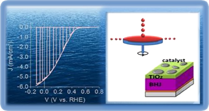
Nowadays, the efficient, stable, and scalable conversion of solar energy into chemical fuels represents a great scientific, economic, and ethical challenge. Amongst the available candidate technologies, photoelectrochemical water-splitting potentially has the most promising technoeconomic trade-off between cost and efficiency. However, research on semiconductors and photoelectrode architectures suitable for H2 evolution has focused mainly on the use of fabrication techniques and inorganic materials that are not easily scalable. Here, we report for the first time an all solution-processed approach for the fabrication of hybrid organic/inorganic photocathodes based on organic semiconductor bulk heterojunctions that exhibit promising photoelectrochemical performance. The sequential deposition of inorganic material, charge-selective contacts, visible-light sensitive organic polymers, and earth-abundant, nonprecious catalyst by spin coating leads to state-of-the-art photoelectrochemical parameters, comprising a high onset potential [+0.602 V vs reversible hydrogen electrode (RHE)] and a positive maximum power point (+0.222 V vs RHE), a photocurrent density as high as 5.25 mA/cm2 at 0 V versus RHE, an incident photon-to-current conversion efficiency at 0 V versus RHE of above 35%, and 100% faradaic efficiency for hydrogen production. The demonstrated all solution-processed hybrid photoelectrodes represent an eligible candidate for the scalable and low-cost solar-to-H2 conversion technology that embodies the feasibility requirements for large area, plant-scale applications.
1. Introduction
Organic semiconductors have attracted considerable interest in cost-effective electricity generation using third-generation photovoltaics (PVs).1,2 Recently, a power conversion efficiency of over 10% has been achieved by the most efficient conjugated polymer semiconductors in state-of-the-art organic PV cells.3 One of the main advantages of polymer semiconductors is their compatibility with flexible devices, as well as with solution-processed, large area deposition techniques.4 In contrast with the PV field, exploitation of the optoelectronic properties of conjugated polymers for photoelectrochemical applications has been scarcely considered.5−10 It is only very recently that polymer-based devices for photoelectrochemical hydrogen production have been reported by a few groups.11−14 By taking advantage of scientific know-how, large material availability, and technological solutions that have already been developed in the organic PV field, efficient organic photocathodes have been demonstrated,15,16 reaching, in some cases, performances comparable with their inorganic counterparts.17,18 Typically, hybrid organic/inorganic architectures have been employed, composed of electron donor/acceptor organic materials in a bulk heterojunction (BHJ) architecture, working as light absorbing and charge generating materials, sandwiched in between inorganic charge-selective layers.14,16−19 The benchmark architecture for hybrid organic/inorganic photoelectrochemical (HOPEC) devices reported so far comprises an organic BHJ (namely, the electron donor regioregular poly(3-hexylthiophene-2,5-diyl) (P3HT) blended with the electron acceptor fullerene derivative [6,6]-phenyl C61 butyric acid methyl ester (PCBM) (P3HT:PCBM)) sandwiched in between a hole-selective layer (HSL), γ-cuprous iodide (CuI), and an electron-selective layer (ESL), amorphous TiO2, deposited by pulsed laser deposition and covered by a sputtered layer of Pt.20 The CuI layer, deposited by spin coating, proved to be very efficient when working as the HSL,21−24 permitting a photocurrent density as high as 8 mA/cm2 at 0 V versus reversible hydrogen electrode (RHE) to be achieved.20
Although these results demonstrate that HOPEC devices represent a promising, alternative approach with respect to more established inorganic photoelectrochemical systems,25,26 their greater potential advantage could be their use in printing for the low-cost fabrication of large area devices. To achieve this, a fully solution-processed architecture is needed. Only very few examples of organic, all solution-processed photocathodes for hydrogen evolution reaction (HER) have been reported so far in the literature.27 In the most relevant example, a maximum photocurrent density of 2 mA/cm2 at 0 V versus RHE was achieved, using MoOx as the HSL and molybdenum trisulfide (MoS3) as a catalyst, on top of the P3HT:PCBM BHJ.28
Thus, the production of a hybrid organic/inorganic photocathode entirely by solution-processed techniques represents a milestone toward device scalability, low cost, fast fabrication, and high-throughput industrial implementation. In parallel, the use of earth-abundant catalysts that are able to replace precious metals and are compatible with solution processing should be considered as well.
Here, our objective is the realization of an all solution-processed photocathode that exhibits competitive performance with respect to previously reported hybrid architectures. In view of this, we develop a low-cost technology compatible with the use of environmentally sustainable catalysts and allowing for easy scale-up of device surface area. We report hybrid organic/inorganic photocathodes that are entirely realized by spin coating in air, using commercial fluorine-doped tin oxide (FTO) as the substrate. These devices show interesting performances in terms of photocurrent generation and achieve the production of hydrogen with near unity faradaic efficiency.
2. Results and Discussion
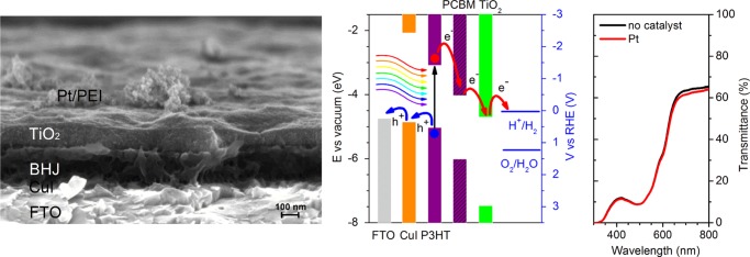
Figure 1a shows the optimized architecture of the all solution-processed photocathode, namely, FTO/CuI/BHJ/TiO2/catalyst/PEI. In this case, Pt and branched poly(ethyleneimine) (PEI) were used as the HER catalyst and organic protective layer, respectively. The CuI, P3HT:PCBM BHJ, and PEI layers were realized as previously reported.20
Figure 1.
All solution-processed photocathode architecture. (a) High-resolution scanning electron micrograph (SEM) cross-sectional image of the different layers comprising the all solution-processed photocathode architecture. From bottom to top: FTO transparent conductive oxide, hole-selective CuI layer, P3HT:PCBM BHJ, electron-selective TiO2 layer and Pt electrocatalyst layer covered by the PEI protective film. Scale bar, 100 nm. (b) Energy band edge positions of the different materials comprising the hybrid photocathode architecture. Charge carrier injection at the different interfaces is schematically shown. Redox levels for both the HER (blue solid line) and the oxygen evolution reaction (blue dashed line) are also shown. (c) UV–visible transmission spectra of the all solution-processed photocathode with Pt catalyst (red) and the same stack fabricated omitting the Pt deposition step (black).
In agreement with recent studies,20 the very thin layer of CuI (thickness <10 nm) enables a very efficient hole collection process, thanks to the good match with the P3HT highest occupied molecular orbital level (Figure 1b) and the electronically favorable and thermodynamically stable crystalline character. The presence of a crystalline γ-phase of CuI (Figure S1) is confirmed by X-ray diffraction (XRD) measurements (Figure S1). The average grain size is 17.4 ± 2.2 nm, as derived from Scherrer peak analysis. A favorable work function (WF) value of CuI, equal to 4.87 ± 0.1 eV, was obtained by ambient Kelvin probe measurements (see Table S1, reporting also the WF values measured for all of the inorganic materials employed in the present photocathode architecture), which is in line with literature values.23,24
During the photoelectrochemical experiments, the photocathodes were illuminated through the FTO–glass substrate. However, even in the presence of the catalyst layer, they display a semitransparent character, as documented by the transmittance spectra (Figure 1c), thus making irradiation possible from both directions. This is a pivotal requirement for the integration of a photocathode with photoanodes in a tandem configuration. The transmission spectrum is mainly dominated by the P3HT absorption band, peaking in the green part of the visible range, at around 500 nm. As documented elsewhere for the P3HT:PCBM BHJ,29 and in agreement with our previous reports,19,20,30 a photoactive layer of around 200 nm in thickness was found to be appropriate for optimal light absorption under simulated illumination at 1 sun intensity.
The deposition of the upper layer on top of the organic BHJ is particularly challenging by solution-processed methods. So far, solution-processed TiO2 fabricated in this way has been scarcely reported as an electron-selective material in photocathode architectures. The most common approach is based on substoichiometric titania nanoparticles dispersed in an organic phase (TiO2(org)).13 However, in our case, this strategy did not yield significant performances, even in the presence of a Pt-based catalyst (Figure S2). Thus, we opted for a completely different approach. According to Yun et al.,31 TiO2 nanoparticles exhibiting the anatase crystalline phase can be obtained by a low temperature sol–gel method in aqueous media (aq). This synthesis was reproduced here with minor modifications (see Section 4). Crystalline TiO2 in the anatase phase was confirmed by XRD measurements, showing a grain size of 5.6 ± 2.2 nm as derived from Scherrer peak analysis (Figure 2).
Figure 2.
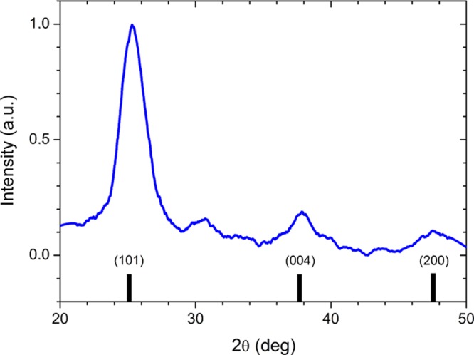
ESL layer structural analysis. XRD pattern (blue solid line) of a TiO2(aq) thin film spin coated over a glass substrate. Reference reflections of anatase TiO2 (black solid lines) are also shown for comparison.
The TiO2(aq) WF is 4.71 ± 0.01 eV, as measured by Kelvin probe analysis (see Table S1). Both the good energetic match with the lowest unoccupied molecular orbital level of the PCBM donor (Figure 1b) and the crystalline morphology are expected to enhance the device photoelectrochemical performance by maximizing electron transfer at the interface and by favoring electronic transport within the layer, respectively. However, the aqueous nature of the TiO2(aq) dispersion can cause significant wettability issues during film formation, due to the incompatible polarity of the underlying organic surface. One fast and efficient way to circumvent such an issue is to modify the surface energy at the interface by applying an oxygen plasma treatment. As the BHJ surface will be exposed to interactions with plasma particles and energy fluxes, care has to be taken to avoid thermal, ballistic, and oxidative damage to the polymer blend. A short and low radio frequency power density surface plasma treatment performed in a pure O2 atmosphere (hereafter denoted by “plasma 1”, 30 s at 60 W power) was thus applied to the BHJ surface, whilst keeping the sample floating at the plasma potential by means of a nonconductive substrate holder. The plasma treatment resulted in enhanced wettability and allowed the formation of a more homogeneous TiO2(aq) layer (100–120 nm thick, Figure 1a). Overall, the replacement of TiO2(org) with TiO2(aq) as the ESL turned out to be highly beneficial, leading to a significant improvement in the photocurrent value (0.8 mA/cm2 at 0 V vs RHE, see Figure S2).
Further efforts toward the realization of efficient photocathodes for hydrogen production have focused on more careful control of the hydrolysis process of the titania layer in air, which is considered an important step in TiOx to TiO2 conversion. We varied the hydrolysis time in air from 10 min up to 3 days, finding a treatment time of 24 h to be the optimum time. Afterward, thermal annealing under an inert atmosphere at 130 °C for 10 min was applied. A Pt catalyst ink was employed (see below for a direct comparison of the effect of different catalysts), leading to clusters of catalyst particles dispersed over the TiO2 surface (see Figures 1a and S3). A thin PEI layer was finally added on top. The latter, according to previous results, is expected to improve the device lifetime by limiting catalyst detachment over time, without affecting photocurrent generation.20 Notably, these optimized conditions allowed the achievement of photocurrents surpassing 1 mA/cm2 at 0 V versus RHE (Figure 3, blue solid line).
Figure 3.
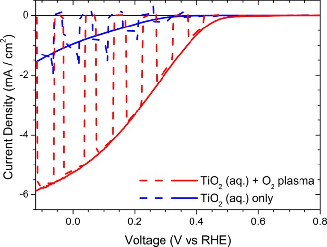
Photoelectrochemical characterization. Current–potential characteristics measured in 0.1 M H2SO4–Na2SO4 solution at pH 1.0, under chopped (dashed line) and continuous (full line) AM 1.5 G light illumination (100 W/cm2) for two different all solution-processed photocathode fabrication strategies. The TiO2(aq) deposition step was followed by O2 plasma treatment in one case (red curve), but not in the other one (blue curve). In both cases, the complete device architecture was FTO/CuI/P3HT:PCBM/TiO2(aq)/Pt/PEI.
Another critical element in the fabrication of efficient and reliable photocathodes is the interface between the ESL and the catalyst layer, where the presence of defects may easily lead to electron recombination losses. We found that a second oxygen plasma treatment (using the same parameters as those of the former one, hereafter denoted as “plasma 2”), in this case on the TiO2(aq) surface prior to catalyst deposition, is of key importance and leads to a further, substantial enhancement in the photocurrent of about +400%. A record photocurrent value of 5.25 mA/cm2 at 0 V versus RHE and an average value of 4.60 ± 0.39 mA/cm2 at 0 V versus RHE (mean values ± SD calculated over six measurements, n = 6) were achieved. The introduction of the additional plasma treatment also leads to higher onset potential values (+0.60 ± 0.01 V vs RHE), as compared to the 0.46 ± 0.01 V versus RHE onset potential measured for the photoelectrode fabricated without the second plasma treatment step. A significant improvement in the fill factor shape of the JV curves is also obtained, characterized by a maximum power point (Vmpp) of +0.22 ± 0.01 V versus RHE and providing a photocurrent of 3.02 ± 0.09 mA/cm2. Moreover, one should note that transient capacitive peaks are completely suppressed upon introduction of the second plasma treatment in the fabrication protocol, thus confirming the improvement of electron transfer processes at the TiO2(aq)/catalyst interface. Overall, these features represent, to the best of our knowledge, state-of-the-art performance for a photocathode entirely fabricated by all solution-processed techniques.
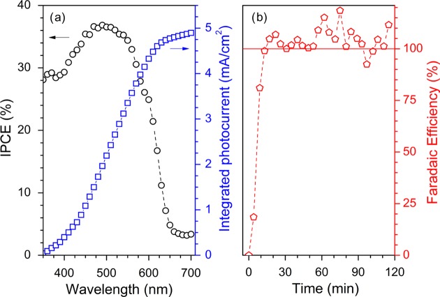
Additional photoelectrochemical characterization of the solution-processed photocathodes was focused on relevant efficiency-based features. The incident photon-to-current conversion efficiency (IPCE) value at 0 V versus RHE is higher than 35% around 500 nm (Figure 4a), where the maximum absorption of the photoactive BHJ layer occurs (Figure 1c). This indicates that more than one-third of the photons arriving at the photocathode are converted into electrons that are capable of driving HER at the catalyst/electrolyte interface. Importantly, the integrated photocurrent (4.90 mA/cm2, blue line) extracted from the IPCE data shows a good match with photocurrent values measured by linear sweep voltammetry (LSV) at 0 V versus RHE. Hydrogen evolution was directly measured by gas chromatography (GC) during a potentiostatic chronoamperometry (CA) scan at fixed potential (0 V vs RHE). The results show that after an initial transient behavior, ascribed to a delay in gas equilibration across the measurement cell, the faradaic efficiency is 100%, and this is maintained over 2 h (Figure 4b). This indicates that all of the electrons extracted at the catalyst/electrolyte interface are consumed by the H+/H2 half-reaction.
Figure 4.
Efficiency-based photoelectrochemical parameters and product analysis. (a) IPCE of the FTO/CuI/P3HT:PCBM/TiO2(aq)/Pt/PEI all solution-processed photocathodes (left axis, black circles) and integration of the IPCE response over the AM 1.5 G spectral flux (right axis, blue squares). (b) Faradaic efficiency, calculated as the ratio between the measured and the expected hydrogen content, is shown as red symbols. H2 evolution was monitored by GC during continuous photocathode operation under simulated sunlight (AM 1.5 G, 100 W/cm2) in the electrolyte solution (0.1 M H2SO4–Na2SO4 at pH 1.0).
The photoelectrochemical performance of the all solution-processed device is comparable when using either water dispersions of commercial platinum (Pt) nanopowder or other widely reported catalyst layer synthesis strategies such as an isopropanol solution of platinum on graphitized-carbon powder (VC-Pt; Vulcan) (Figure 5, red and blue solid lines, respectively). However, the need to reduce the use of precious materials prompted us to develop architectures based on earth-abundant catalysts. MoS3 has been reported as a good HER catalyst with a low overpotential,11,16 and represents a viable option toward the realization of low-cost hydrogen production systems. A dispersion of commercial MoS3 powder in water/acetone (1:2 v/v) was deposited by spin coating on top of the plasma-treated TiO2 surface, without any further postprocessing treatment. The photoelectrochemical response of the FTO/CuI/BHJ/TiO2/MoS3 photocathode is comparable with those of the photocathodes obtained with Pt-based catalysts (Figure 5). The average photocurrent (measured at 0 V vs RHE) and onset potential values are 3.94 ± 0.13 mA/cm2 and 0.57 ± 0.05 V versus RHE, respectively. Similar to the Pt-based catalyst, MoS3 tends to form clusters of amorphous particles dispersed on top of the TiO2 surface rather than a conformal layer (Figures S1 and S3). Importantly, optical absorption spectra show that the MoS3 catalyst layer does not affect light transmission across the device (Figure S4).
Figure 5.
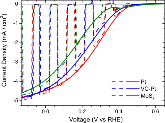
Photoelectrochemical performance of photocathode architectures with different electrocatalyst layers. Current–potential characteristics of different all solution-processed photocathode architectures (FTO/CuI/P3HT:PCBM/TiO2/catalyst) measured at pH 1 under simulated AM 1.5 G illumination (dashed lines for chopped illumination, solid lines for continuous illumination) using platinum nanopowder (Pt), VC-Pt, and Pt-free catalyst (MoS3).
A practical indicator for the evaluation of photoelectrode performance is the ideal ratiometric power-saved figure of merit, Φsaved,ideal.32 In the case of HER driven by a photocathode at Vmpp under solar power input Ps = 100 mW/cm2, with respect to an ideally nonpolarizable dark electrode (i.e., the RHE, with VRHE = 0 at any current), Φsaved,ideal is defined as
Hence, it provides information about the ability of a photocathode to achieve H2 evolution at potentials that are more positive than the thermodynamic potential of H+/H2. For the Pt case (Jmpp = 3.02 mA/cm2 and Vmpp = +0.22 V vs RHE), we obtain Φsaved,ideal = 0.67%, whereas in the case of MoS3 (Jmpp = 2.18 mA/cm2 and Vmpp = +0.17 V vs RHE), Φsaved,ideal = 0.38%. The difference comes from the larger HER overpotential exhibited by the latter catalyst, and could also be affected by a poorer alignment between the respective Fermi levels at the TiO2/MoS3 interface (Table S1).
Lastly, the temporal behavior of a photocathode is an important aspect to consider for the long-lasting exploitation of devices. We should recall that previous studies have shown that conjugated polymers, and in particular P3HT, preserve their optoelectronic properties when in contact with aqueous electrolytes.33,34 In addition, we have recently demonstrated that a thin PEI coating on top of a conformal layer of Pt catalyst helps to prevent catalyst delamination during photocathode operation and possibly limits, to some extent, electrolyte permeation toward the inner layers, thus overall improving the photocurrent stability.20 Here, we tested the same approach with the all solution-processed Pt-based photocathode. The introduction of a protective coating leads to a significant improvement in photocurrent stability. The PEI-capped devices provide 3 mA/cm2 even after 40 min of continuous operation, in contrast to less than 500 μA/cm2 for the uncovered Pt photocathode (Figure S5). Overall, an extended performance is obtained (reaching 1 mA/cm2 after 100 min of operation) with respect to the uncapped device. This can be ascribed to the chelating properties of PEI to metallic ions35,36 and metals.37 The MoS3-based device was intrinsically more stable with respect to the uncoated Pt-based one, showing about 2 mA/cm2 after 40 min of continuous operation (Figure S5). Unfortunately, a detrimental effect on photocurrent stability was observed in the PEI-capped MoS3 devices. Elucidation of the detailed reasons for such an unexpected detrimental effect is currently ongoing. In general, optimization of the stability properties of hybrid devices will require deeper and more careful optimization of the interfaces between the organic and the inorganic layers, especially under harsh electrolytic environments such as strong acids.
3. Conclusions
In conclusion, we demonstrate that a fast fabrication technique, entirely based on solution processing, can be employed for the realization of low-cost photocathodes. To the best of our knowledge, state-of-the-art performances for polymer-based photocathodes have been reported here, showing photoelectrochemical parameters that are comparable with other all solution-processed devices making use of inorganic semiconductors, such as CuInS2.38 This has been made possible by the combination of different key steps, including the use of anatase phase TiO2(aq) as the ESL, which avoids the use of high temperatures; careful optimization of the BHJ/TiO2 and TiO2/catalyst interfaces, which have a critical impact on device performance; and the development of techniques that are fully compatible with the use of earth-abundant catalysts.
Our method contributes to advancing the development of laboratory prototypes into large area, light and flexible systems for hydrogen production, employing the same techniques and fabrication facilities already developed in the field of printed organic PVs.
4. Experimental Section
4.1. Materials and Photocathode Fabrication
Photocathodes were fabricated on commercial FTO. Substrates were cleaned by subsequent ultrasonic baths with a series of solvents. CuI (Sigma-Aldrich; 97% purity) was dissolved in acetonitrile (Sigma-Aldrich, American Chemical Society (ACS) grade) at 10 g/L concentration. CuI deposition was carried out by spin coating in one single step (3000 rpm rotation speed for 60 s). rr-P3HT (purchased from Sigma-Aldrich and used without further purification, molecular weight (MW) 15 000–45 000, purity 99.995%) and fullerene derivative PCBM (purchased from Nano-C, Inc.) were individually dissolved in chlorobenzene (Sigma-Aldrich; ACS grade) and then mixed at a 1:1 wt ratio and at 25 g/L on a polymer basis. The blend solution was stirred overnight at 50 °C. The active layer was spin coated on top of the CuI layer in a two-step process (800 rpm for 3 s, followed by 1600 rpm for 60 s).
Organic-based TiOx nanoparticles were synthesized according to ref (13).
Titanium tetraisopropoxide (TTIP 97%; Sigma-Aldrich) was dissolved in a mixture of ethanol/isopropanol (5:5 mL) to provide a concentration of 0.05 mol/L. Then, concentrated HCl was added as the acid catalyst to provide a water to TTIP molar ratio of 0.82. The precursor solution was stirred for 72 h at room temperature in a sealed vial. This sol was spin coated on top of the BHJ surface at 1000 rpm for 60 s. Aqueous-based TiO2 nanoparticles were synthesized according to a modified sol–gel protocol31 that comprises a mixture of titanium TTIP (97%, Sigma-Aldrich) in ethanol and water to obtain a TTIP/ethanol/water molar ratio of 1:0.75:83. Then, 1 mL of concentrated hydrochloric acid instead of concentrated nitric acid was added as the acid catalyst and the resulting sol was refluxed under vigorous stirring for 8 h at 80 °C, finally reaching a stable milky dispersion of TiOx nanoparticles at 15% concentration in weight under a Ti-basis. A 30 s low power (60 W) oxygen plasma treatment (plasma 1) was applied to the surface of the BHJ to enhance the wettability of the aqueous-based titania dispersion. A three-step spin coating protocol was employed comprising 3 s at 200 rpm, 60 s at 1000 rpm, and 30 s at 5000 rpm. Afterward, thermal annealing under an inert atmosphere at 130 °C for 10 min was applied followed by a plasma treatment like before (plasma 2) just prior to catalyst deposition.
Commercial platinum nanopowder (Sigma-Aldrich) was dissolved in water at 1 g/L concentration in weight and sonicated for 30 min. The commercial catalyst Vulcan XC-72 (20% loading VC-Pt; Sigma-Aldrich) was dissolved in isopropanol at 1 g/L concentration in weight and sonicated for 30 min. Commercial MoS3 powder (Thermo Fisher Scientific Inc.) was dissolved in a water/acetone mixture at a volume ratio of 1:2 in the presence of 1 M NaOH to a mass concentration of 3.8 g/L. The dispersion was stirred at 70 °C for 2 h and then sonicated for 30 min. The three catalyst dispersions were spin coated at 2000 rpm for 60 s each. Branched PEI (MW 25 000 g/mol, Sigma-Aldrich) was dissolved in ethanol at 0.1% concentration and spin coated on top of the full devices at 3000 rpm for 60 s. Further details on material preparation can be found in the Supporting Information section.
4.2. Material Characterization Techniques
UV–visible transmittance was collected using a PerkinElmer LAMBDA 1050 spectrophotometer. An α-Step IQ surface profilometer was used to measure the thickness of the BHJ film. Thickness was also confirmed by SEM cross-sectional measurements using a Zeiss Supra 40 field-emission SEM instrument under an operating voltage of 5 kV and a working distance of 2 mm. WF data were obtained using a commercial Kelvin probe system (KPSP020; KP Technologies Inc.). Samples were measured in air and at room temperature and both a clean gold surface (WF = 4.8 eV) and a graphite sample (highly ordered pyrolytic graphite, WF = 4.6 eV) were used as independent references for the probe potential. X-ray powder diffraction experiments were carried out on a Bruker D8 Advance diffractometer operating in 2θ configuration for thin film analysis with Ge-monochromated Cu KR1 radiation (λ = 1.5406 Å) and a linear position-sensitive detector, with a 2θ range of 20–80° and a step size of 0.015°. Crystalline grain size was derived through Scherrer’s formula from the anatase {101} crystalline peak. Error bars in crystallite grain size and crystalline volume fraction data-points were derived by error propagation of standard deviations of XRD peak full width at half-maximum (FWHM) values and areas derived by XRD pattern fitting.
4.3. Photoelectrochemical Measurements
Photoelectrochemical measurements were carried out at room temperature in a flat-bottom fused silica cell under a three-electrode configuration using an Autolab PGSTAT302N potentiostat/galvanostat station, equipped with the Nova 1.8 (Metrohm) software package. A Pt wire was used as the counter electrode and Ag/AgCl, saturated with KCl, was used as the reference electrode. Measurements were performed in 50 mL of an aqueous solution of 0.1 M H2SO4 (Sigma-Aldrich, 99.999% purity)/0.1 M Na2SO4 (Sigma-Aldrich, purity 99.0%) at pH 1.0. Oxygen was purged from testing electrolyte solutions by continuously flowing nitrogen gas throughout the liquid volume using a porous frit for at least 30 min before starting measurements. A constant, slight nitrogen flow was maintained afterward for the whole duration of the experiments, to avoid redissolution of molecular oxygen into the electrolyte. Potential differences between the working electrode and the reference electrode were reported with respect to the RHE scale using the Nernst equation. A 300 W Xenon light source (model LS0306; LOT-QuantumDesign Ltd.), equipped with AM 1.5 G filters, was used to simulate solar illumination conditions at the glass substrate side of the samples inside the test cell.
LSV was employed to evaluate the response of the devices in the dark and under chopped illumination. Voltage was swept starting above the open circuit potential of the electrochemical cell toward cathodic potentials below 0 V versus RHE at a scan rate of 10 mV/s. Stability tests were performed by running potentiostatic CA at 0 V versus RHE, under continuous illumination, and monitoring dark current values from time to time.
For analysis of the evolved gas products, the hybrid photocathode was fixed inside a gas-tight test cell with a quartz window and illuminated from the glass substrate side by a 450 W xenon lamp (ozone-free; Osram), equipped with a KG3 filter (LOT-QuantumDesign Ltd.) and calibrated to 1 sun illumination intensity by a Si photodiode. Measurements were conducted by running CA measurements in three-electrode configuration at 0 V versus RHE at pH 1 while maintaining rapid magnetic stirring. Helium gas at 20 mL/min flow was continuously bubbled through the cell with the out-flow periodically injected into a GC (TRACE Ultra with a pulsed discharge detector; Thermo Fisher Scientific Inc.; ShinCarbon ST column; Restek) for in-line characterization of evolved hydrogen. The Pt wire counter electrode was held behind a porous ceramic frit to minimize product crossover. The GC response was calibrated within the same cell and gas flow conditions using a dedicated Pt wire under galvanostatic hydrogen evolution at known rates.
IPCE measurements were performed using a 300 W xenon lamp (Cermax PE 300 BUV) light source and a monochromator (FWHM 10 nm; Bausch & Lomb) between 350 and 700 nm. The photocathode was fixed inside a test cell equipped with a quartz window and illuminated from the glass substrate side using a shadow mask with 0.64 cm2 aperture. The photocurrent response data were collected by running CA measurements in three-electrode configuration at 0 V versus RHE and at pH 1, and were further normalized against a calibrated silicon photodiode (FDS-100; Thorlabs Inc.) to determine the IPCE values at each wavelength.
Acknowledgments
This work was supported by the EU through the Future and Emerging Technologies (FET) program under the FP7, Collaborative Project 309223 (PHOCS, Photogenerated Hydrogen by Organic Catalytic Systems).
Supporting Information Available
The Supporting Information is available free of charge on the ACS Publications website at DOI: 10.1021/acsomega.7b00558.
Experimental methods; photocathodes layers structural analysis; WF measurements; photoelectrochemical performance of photocathode architectures with different ESL layers preparation; SEM images; photocathodes optical characterization; photocathodes chronoamperometric photoelectrochemical characterization (PDF)
Author Contributions
H.C.R. planned the work and optimized the fabrication, helped by S.B. H.C.R. and S.B. carried out electrochemical characterization. E.A.S. synthesized the aqueous sol TiOx. F.F. carried out XRD experiments. M.T.M. and M.S. carried out GC and IPCE measurements. F.D.F. carried out SEM analysis. M.R.A. planned and supervised the work. All authors contributed to the interpretation of the results and to manuscript drafting.
The authors declare no competing financial interest.
Supplementary Material
References
- Facchetti A. π-Conjugated Polymers for Organic Electronics and Photovoltaic Cell Applications. Chem. Mater. 2011, 23, 733–758. 10.1021/cm102419z. [DOI] [Google Scholar]
- Dou L.; Liu Y.; Hong Z.; Li G.; Yang Y. Low-Bandgap Near-IR Conjugated Polymers/Molecules for Organic Electronics. Chem. Rev. 2015, 115, 12633–12665. 10.1021/acs.chemrev.5b00165. [DOI] [PubMed] [Google Scholar]
- Green M. A.; Emery K.; Hishikawa Y.; Warta W.; Dunlop E. D. Solar cell efficiency tables (Version 45). Prog. Photovoltaics 2015, 23, 1–9. 10.1002/pip.2573. [DOI] [Google Scholar]
- Caironi M.; Noh Y. Y.. Large Area and Flexible Electronics; John Wiley and Sons: New York, 2015; pp 439–463. [Google Scholar]
- Winther-Jensen O.; Winther-Jensen B.; MacFarlane D. R. Photostimulated electrocatalysis of water oxidation by conjugated polymers. Electrochem. Commun. 2011, 13, 307–309. 10.1016/j.elecom.2011.01.008. [DOI] [Google Scholar]
- El-Rashiedy O. A.; Holdcroft S. Photoelectrochemical Properties of Poly(3-alkylthiophene) Films in Aqueous Solution. J. Phys. Chem. 1996, 100, 5481–5484. 10.1021/jp953186a. [DOI] [Google Scholar]
- Suppes G.; Ballard E.; Holdcroft S. Aqueous photocathode activity of regioregular poly(3-hexylthiophene). Polym. Chem. 2013, 4, 5345–5351. 10.1039/c3py00143a. [DOI] [Google Scholar]
- Sprick R. S.; Jiang J.-X.; Bonillo B.; Ren S.; Ratvijitvech T.; Guiglion P.; Zwijnenburg M. A.; Adams D. J.; Cooper A. I. Tunable Organic Photocatalysts for Visible-Light-Driven Hydrogen Evolution. J. Am. Chem. Soc. 2015, 137, 3265–3270. 10.1021/ja511552k. [DOI] [PubMed] [Google Scholar]
- Lanzarini E.; Antognazza M. R.; Biso M.; Ansaldo A.; Laudato L.; Bruno P.; Metrangolo P.; Resnati G.; Ricci D.; Lanzani G. Polymer-Based Photocatalytic Hydrogen Generation. J. Phys. Chem. C 2012, 116, 10944–10949. 10.1021/jp212107f. [DOI] [Google Scholar]
- Bornoz P.; Prévot M. S.; Yu X.; Guijarro N.; Sivula K. Direct Light-Driven Water Oxidation by a Ladder-Type Conjugated Polymer Photoanode. J. Am. Chem. Soc. 2015, 137, 15338–15341. 10.1021/jacs.5b05724. [DOI] [PMC free article] [PubMed] [Google Scholar]
- Bourgeteau T.; Tondelier D.; Geffroy B.; Brisse R.; Laberty-Robert C.; Campidelli S.; de Bettignies R.; Artero V.; Palacin S.; Jousselme B. A H2-evolving photocathode based on direct sensitization of MoS3 with an organic photovoltaic cell. Energy Environ. Sci. 2013, 6, 2706–2713. 10.1039/c3ee41321g. [DOI] [PMC free article] [PubMed] [Google Scholar]
- Gustafson M. P.; Clark N.; Winther-Jensen B.; MacFarlane D. R. Organic Photovoltaic Structures as Photo-active Electrodes. Electrochim. Acta 2014, 140, 309–313. 10.1016/j.electacta.2014.03.112. [DOI] [Google Scholar]
- Haro M.; Solis C.; Molina G.; Otero L.; Bisquert J.; Gimenez S.; Guerrero A. Toward Stable Solar Hydrogen Generation Using Organic Photoelectrochemical Cells. J. Phys. Chem. C 2015, 119, 6488–6494. 10.1021/acs.jpcc.5b01420. [DOI] [Google Scholar]
- Guerrero A.; Haro M.; Bellani S.; Antognazza M. R.; Meda L.; Gimenez S.; Bisquert J. Organic photoelectrochemical cells with quantitative photocarrier conversion. Energy Environ. Sci. 2014, 7, 3666–3673. 10.1039/C4EE01775G. [DOI] [Google Scholar]
- Lai L.-H.; Gomulya W.; Berghuis M.; Protesescu L.; Detz R. J.; Reek J. N. H.; Kovalenko M. V.; Loi M. A. Organic–Inorganic Hybrid Solution-Processed H2 Evolving Photocathodes. ACS Appl. Mater. Interfaces 2015, 7, 19083–19090. 10.1021/acsami.5b04550. [DOI] [PubMed] [Google Scholar]
- Bourgeteau T.; Tondelier D.; Geffroy B.; Brisse R.; Cornut R.; Artero V.; Jousselme B. Enhancing the performances of P3HT:PCBM–MoS3 based H2 evolving photocathodes with interfacial layers. ACS Appl. Mater. Interfaces 2015, 7, 16395–16403. 10.1021/acsami.5b03532. [DOI] [PMC free article] [PubMed] [Google Scholar]
- Azevedo J.; Steier L.; Dias P.; Stefik M.; Sousa C. T.; Araujo P.; Mendes A.; Grätzel M.; Tilley S. D. On the stability enhancement of cuprous oxide water splitting photocathodes by low temperature steam annealing. Energy Environ. Sci. 2014, 7, 4044–4052. 10.1039/C4EE02160F. [DOI] [Google Scholar]
- Septina W.; Gunawan G.; Ikeda S.; Harada T.; Higashi M.; Abe R.; Matsumura M. Photosplitting of Water from Wide-Gap Cu(In,Ga)S2 Thin Films Modified with a CdS Layer and Pt Nanoparticles for a High-Onset-Potential Photocathode. J. Phys. Chem. C 2015, 119, 8576–8583. 10.1021/acs.jpcc.5b02068. [DOI] [Google Scholar]
- Fumagalli F.; Bellani S.; Schreier M.; Leonardi S.; Comas Rojas H.; Ghadirzadeh A.; Tullii G.; Savoini A.; Marra G.; Meda L.; Grätzel M.; Lanzani G.; Mayer M. T.; Antognazza M. R.; Di Fonzo F. Hybrid organic–inorganic H2-evolving photocathodes: understanding the route towards high performance organic photoelectrochemical water splitting. J. Mater. Chem. A 2016, 4, 2178–2187. 10.1039/C5TA09330A. [DOI] [Google Scholar]
- Rojas H. C.; Bellani S.; Fumagalli F.; Tullii G.; Leonardi S.; Mayer M. T.; Schreier M.; Grätzel M.; Lanzani G.; Di Fonzo F.; Antognazza M. R. Polymer-based photocathodes with a solution-processable cuprous iodide anode layer and a polyethyleneimine protective coating. Energy Environ. Sci. 2016, 9, 3710–3723. 10.1039/C6EE01655C. [DOI] [Google Scholar]
- Sun W.; Peng H.; Li Y.; Yan W.; Liu Z.; Bian Z.; Huang C. Solution-Processed Copper Iodide as an Inexpensive and Effective Anode Buffer Layer for Polymer Solar Cells. J. Phys. Chem. C 2014, 118, 16806–16812. 10.1021/jp412784q. [DOI] [Google Scholar]
- Peng Y.; Yaacobi-Gross N.; Perumal A. K.; Faber H. A.; Vourlias G.; Patsalas P. A.; Bradley D. D. C.; He Z.; Anthopoulos T. D. Efficient organic solar cells using copper(I) iodide (CuI) hole transport layers. Appl. Phys. Lett. 2015, 106, 243302 10.1063/1.4922758. [DOI] [Google Scholar]
- Shao S.; Liu J.; Zhang J.; Zhang B.; Xie Z.; Geng Y.; Wang L. Interface-Induced Crystalline Ordering and Favorable Morphology for Efficient Annealing-Free Poly(3-hexylthiophene):Fullerene Derivative Solar Cells. ACS Appl. Mater. Interfaces 2012, 4, 5704–5710. 10.1021/am3017653. [DOI] [PubMed] [Google Scholar]
- Das S.; Choi J. Y.; Alford T. L. P3HT:PC61BM based solar cells employing solution processed copper iodide as the hole transport layer. Sol. Energy Mater. Sol. Cells 2015, 133, 255–259. 10.1016/j.solmat.2014.11.004. [DOI] [Google Scholar]
- Sivula K.; Van de Krol R. Semiconducting materials for photoelectrochemical energy conversion. Nat. Rev. Mater. 2016, 1, 15010. 10.1038/natrevmats.2015.10. [DOI] [Google Scholar]
- Septina W.; Tilley D. Emerging Earth-abundant materials for scalable solar water splitting. Curr. Opin. Electrochem. 2017, 120–127. 10.1016/j.coelec.2017.03.010. [DOI] [Google Scholar]
- Bellani S.; Najafi L.; Capasso A.; Del Rio Castillo A. E.; Antognazza M. R.; Bonaccorso F. Few-layer MoS2 flakes as a hole-selective layer for solution-processed hybrid organic hydrogen-evolving photocathodes. J. Mater. Chem. A 2017, 5, 4384–4396. 10.1039/C6TA10572F. [DOI] [Google Scholar]
- Bourgeteau T.; Tondelier D.; Geffroy B.; Brisse R.; Campidelli S.; Cornuta R.; Jousselme B. All solution-processed organic photocathodes with increased efficiency and stability via the tuning of the hole-extracting layer. J. Mater. Chem. A 2016, 4, 4831–4839. 10.1039/C6TA01320A. [DOI] [Google Scholar]
- Dennler G.; Scharber M. C.; Brabec C. J. Polymer-fullerene bulk-heterojunction solar cells. Adv. Mater. 2009, 21, 1323–1338. 10.1002/adma.200801283. [DOI] [Google Scholar]
- Mezzetti A.; Fumagalli F.; Alfano A.; Iadicicco D.; Antognazza M. R.; Di Fonzo F. Stable hybrid organic/inorganic photocathodes for hydrogen evolution with amorphous WO3 hole selective contacts. Faraday Discuss. 2017, 433–448. 10.1039/C6FD00216A. [DOI] [PubMed] [Google Scholar]
- Yun Y. J.; Chung J. S.; Kim S.; Hahn S. H.; Kim E.-J. Low-temperature coating of sol–gel anatase thin films. Mater. Lett. 2004, 58, 3703–3706. 10.1016/j.matlet.2004.07.018. [DOI] [Google Scholar]
- Coridan R. H.; Nielander A. C.; Francis S. A.; McDowell M. T.; Dix V.; Chatman S. M.; Lewis N. S. Methods for Comparing the Performance of Energy-Conversion Systems for Use in Solar Fuels and Solar Electricity Generation. Energy Environ. Sci. 2015, 8, 2886–2901. 10.1039/C5EE00777A. [DOI] [Google Scholar]
- Bellani S.; Fazzi D.; Bruno P.; Giussani E.; Canesi E. V.; Lanzani G.; Antognazza M. R. Reversible P3HT/Oxygen charge transfer complex identification in thin films exposed to direct contact with water. J. Phys. Chem. C 2014, 118, 6291–6299. 10.1021/jp4119309. [DOI] [Google Scholar]
- Antognazza M. R.; Ghezzi D.; Musitelli D.; Garbugli M.; Lanzani G. A hybrid solid-liquid polymer photodiode for the bioenvironment. Appl. Phys. Lett. 2009, 94, 243501 10.1063/1.3153846. [DOI] [Google Scholar]
- Jia J.; Wu A.; Luan S. Spectrometry recognition of polyethyleneimine towards heavy metal ions. Colloids Surf., A 2014, 449, 1–7. 10.1016/j.colsurfa.2014.02.032. [DOI] [Google Scholar]
- Kislenko V. N.; Oliynyk L. P. Complex Formation of Polyethyleneimine with Copper(II), Nickel(II), and Cobalt(II) Ions. J. Polym. Sci., Part A: Polym. Chem. 2002, 40, 914–922. 10.1002/pola.10157. [DOI] [Google Scholar]
- Kang H.; Jung S.; Jeong S.; Kim G.; Lee K. Polymer-metal hybrid transparent electrodes for flexible electronics. Nat. Commun. 2015, 6, 6503 10.1038/ncomms7503. [DOI] [PMC free article] [PubMed] [Google Scholar]
- Guijarro N.; Prévot M. S.; Yu X.; Jeanbourquin X. A.; Bornoz P.; Bourée W.; Johnson M.; Le Formal F.; Sivula K. A bottom-up approach toward all-solution-processed high-efficiency Cu(In,Ga)S2 photocathodes for solar water splitting. Adv. Energy Mater. 2016, 6, 1501949 10.1002/aenm.201501949. [DOI] [Google Scholar]
Associated Data
This section collects any data citations, data availability statements, or supplementary materials included in this article.


