Abstract
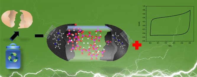
Flexible batteries and supercapacitors (SCs) are expected to play a crucial role in energy storage and management in portable electronic devices. In addition, use of materials based on renewable resources would allow for more affordable and sustainable gadgets. In this context, eggshell membranes (ESMs) represent a promising functional platform for production of high-performance electronic components. In this work, we use ESMs for preparing flexible SCs through the incorporation of carbon nanotubes and subsequent in situ polymerization of polypyrrole, producing a highly conductive nanostructure characterized by a porous surface that exhibits both faradic and nonfaradic mechanisms for charge storage. We have found that by controlling the conducting polymer/carbon derivative relative concentration, one can maximize the corresponding capacitance to attain values up to the order 564.5 mF/cm2 (areal capacitance), 24.8 F/cm3 (volumetric capacitance), and 357.9 F/g (gravimetric capacitance). These bioinspired flexible devices exhibit a capacitance retention of 60% after 4000 cycles of charge/discharge and present negligible aging even after 500 bending repetitions (at a density of current 5 mA/cm2). The successful use of ESM-based electrodes in association with carbon derivatives/conducting polymers confirm that the exploit of biological materials offers a promising perspective for the development of new ecofriendly electronic devices.
1. Introduction
The increasing limitation in the availability of fossil and conventional energy sources has encouraged the pursuit of more efficient power sources, such as photovoltaic, piezoelectric, geothermal, among others. Despite considerable progress made in that direction in recent years, the pace of development of these alternative technologies remains intermittent, and their more widespread use in practical devices will only become reality with proper energy management and storage. In this regard, the search for more efficient electrochemical devices continues to be a fundamental task.1,2 Among these, supercapacitors (SCs) stand out as specially promising alternative, not only due to their characteristic fast charge–discharge (CD) processes but also for their high power density, high cyclability, and long life when their properties are compared to those of batteries.3−5 These characteristics make SC fill an optimal operational niche apart from batteries and electrostatic capacitors, enabling the possibility of storing and delivering charges at superior levels. More recently, with the introduction of portable and wearable devices and the simultaneous rise of the “internet of things,” the development of electronics is experiencing a rapid transition from classical rigid to lightweight flexible structures.6,7 Integration of SCs in these new devices would allow for both a fast harvesting of energy and a more efficient and optimized management of its consumption. As an imperative requirement, however, these novel SCs must be lightweight, inexpensive, flexible, stretchable, and able to be adapted in the most capricious forms while preserving their function even under repeated deformation. Fibers from natural and synthetic polymers possess the ideal morphology for use in such devices, as their uniaxial structure gives them the advantage of transmitting forces along their length, reinforcing their mechanical properties while reducing the amount of material that would be otherwise required.7 These benefits go further than those from mere physical support, as fibers can be used to create porous membranes that would allow the assembly of multiple nanostructures and multifunctional hierarchical structures.8 The combination of such characteristics makes these fibers promising building blocks for designing innovative SCs. In fact, several works in the recent literature discuss the use of natural materials, such as cellulosic fibrils from wood,9−11 bacteria,12−14 and cotton,15−17 or those of synthetic polymers,18−20 such as in the case of fibers produced by electrospinning. Although these previous works exploit the benefits of using three-dimensional (3D) templates for the development of flexible SCs, there are still disadvantages associated with their production, such as the requirements of laborious procedures and, in some cases, of use of a considerable amount of toxic solvents. Considering those requirements, in the present article we describe the use of eggshell membrane (ESM) as an ecofriendly template for the assemblage of nanostructures with excellent capacitive properties. As a refined and elegant material developed by nature, ESMs exhibit a porous structure constituted by proteins that evolved to play crucial roles in the development of the chicken embryo, such as the protection conferred by the crystallization of CaCO3 and the critical proviso of adequate gas exchange.21,22 From a material science perspective, this hierarchical structure is a fascinating scaffold for the tailoring of functional nanostructures that could benefit from its good mechanical resistance, flexibility, biodegradability, and porosity and exploit the abundant presence of carboxylic, amino, and hydroxyl functional groups to incorporate active materials.23,24 In addition, one of the most attractive sustainable aspects of using ESM residues is the widespread availability of eggshell as a waste material24 from which a preformed membrane can be easily recuperated, dispensing the use of special resources for its treatment or preparation. Indeed, in recent years, ESM has been considered as a convenient biotemplate to produce self-standing composites for diverse applications, such as sensors,25−27 adsorbents for water remediation,28,29 catalysis,30−33 fuel cells,34,35 and batteries.36,37 Of particular interest to us is their use in SCs as ESM electrodes38,39 and as separators, both in their in natural40 or modified41 forms.
In this work, we propose the use of ESM as scaffolds for the development of hybrid SCs. For this goal, we decided to combine two electroactive materials, viz., multiwall carbon nanotubes (MWCNTs),42 which are known to present electrochemical double-layer capacitance, and polypyrrole (PPy), an intrinsically conducting polymer that has a faradic behavior.43 The resulting hybrid composite has some specific advantages that result from the synergistic interactions between the high power density and cycling stable CNTs and the polymer, wherein fast redox reactions are known to occur.44−47
The strategy we adopted involved modification of the membrane by the electrostatic assembly of MWCNTs on the pristine ESM, which was followed by in situ polymerization of pyrrole (Py). The ESM’s special properties allow the preparation of hybrid electrodes in a simple manner, wherein no binders are used or special chemical modifications required.
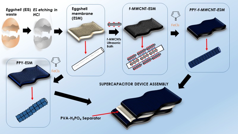
The resulting increase in the final charge storage capacity of the prepared devices relies in the relevant characteristics of these membranes, which not only offer adequate mechanical support but can also act as efficient electrolyte reservoir because of their high porosity. With this, the charge transfer processes in the devices are not confined to a single interface but actually become a bulk phenomenon. In the flexible SC devices discussed here, we employed a poly(vinyl alcohol) (PVA)–phosphoric acid (H3PO4) layer as a separator. To the best of our knowledge, this is the first time that the ESM simple architecture is exploited for the design of lightweight flexible SCs. In Figure 1, we present an illustrative flowchart of the device preparation, considering the devices prepared in the presence (PPy–f-MWCNT–ESMs) and absence of MWCNT (PPy–ESMs).
Figure 1.
Illustrative scheme for PPy–f-MWCNT–ESM devices preparation.
2. Results and Discussion
2.1. Morphology and Structure
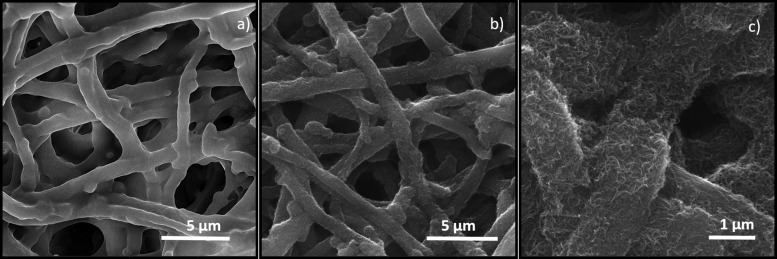
Due to the need of allowing different types of mass, gas, and liquid transfer processes for the exchange of nutrients and products, typically biomaterials have a porous and hierarchical structure. These characteristics have motivated previous works to exploit the ESM chemical composition and morphology for producing porous carbonized electrodes.38,39 Considering these examples, we have found that in a manner somewhat similar to the case of cellulose fibers,12 the ESMs themselves offer a perfect combination of chemical composition, structure, and mechanical properties for flexible electrodes. As it is possible to observe in Figure 2a, ESM (in this case, its outer membrane) exhibits a 3D porous framework constituted by microfibers (1.95 ± 1.28 μm), which are composed mainly of collagen types I, V, and X48 known to exhibit a vast number of amino, carboxylic, and hydroxyl groups, among other functional moieties. Such proteic composition can favor interaction with molecules and some charged nanostructures. As mentioned above, we have prepared mixed membranes of two types: in the first, PPy was grown directly into pristine ESM, whereas in the other, carbon nanotubes (CNTs) were first incorporated into the ESM and then the polymerization of Py was promoted.
Figure 2.
Scanning electron microscopy (SEM) images of pristine ESM (a), f-MWCNT–ESM (b), and magnified image of f-MWCNT–ESM (c).
As ESM is an electrical insulator, our main purpose for the incorporation of MWCNTs was to increase the electrical conductivity of the modified samples. For this task, we took advantage of the chemical composition of the ESM to assemble the functionalized MWCNT (f-MWCNT) on its surface under ultrasonication. At this point, it is necessary to stress that ultrasonication guarantees good dispersion of the f-MWCNTs, thus avoiding the use of surfactants that could influence the final properties of the composite or inhibit their adsorption in the ESM. In fact, ultrasonication speeds up the adsorption of f-MWCNTs on the ESM, as the associated microjets and shock waves favor the carrying of the f-MWCNTs, which will collapse on the ESM fibers surface. In that way, a combination of physical forces provided by the ultrasonication and the chemical contribution of electrostatic forces, hydrogen bonding, and hydrophobic interactions between the functional groups in the fibers and in the f-MWCNTs accounts for the continuing deposition of the latter.49 As shown in the corresponding SEM images (Figure 2b,c), although the integrity of the membrane is preserved, the surface of the modified fibers becomes rougher due to the increasing density of incorporated f-MWCNTs.
The simplicity of this process should be contrasted to the laborious procedures usually adopted to coat a nonwoven (such as paper, electrospun fibers, or cotton) matrix with MWCNTs, when a surfactant must be used to produce an ink, which is then applied with a binding polymer to the material surface, normally with the help of high-energy ultrasonication.10,50,51
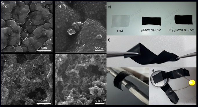
The inclusion of PPy on the ESM and f-MWCNT–ESM was carried through an in situ polymerization methodology by utilizing a 1:1 Py/FeCl3 ratio, whereas the Py concentration was varied from 0.01 to 0.08 M. As shown in Figure S1, one can note that the amount of PPy per square centimeter becomes larger with the increase in the Py concentration used. When comparing the resulting morphology of the two membranes, the most obvious difference lies in the porosity, which is almost lost in the PPy–ESM sample (Figure S2a) but preserved in the other (Figure S2b). This difference could be explained by considering that the presence of f-MWCNTs provides several carboxylic groups that possess high affinity toward intrinsically conducting polymers.52 As can be observed in Figure 3c,d, the PPy growth occurs mainly along the axial directions; in contrast, when no such groups are present, the polymer is formed in all directions, reducing the ESM porosity—see Figure 3a,b.
Figure 3.
SEM images of PPy–ESM complex (a, b) and PPy–f-MWCNT–ESM (c, d) complex at increasing scale of magnification. Digital photos of ESM, f-MWCNT–ESM, and PPy–f-MWCNT–ESM (e). Response to mechanical stimulus (f, g) and characteristic low resistance, applied as conducting wire in a circuit (h) of sample PPy–f-MWCNT–ESM.
The second feature that deserves attention is the difference in morphology, as the presence of clusters of PPy nanoparticles can be identified in the PPy–ESM samples, whereas the PPy–f-MWCNT–ESMs exhibit nanotubular structures. Such changes can be explained by the progress in polymerization process. In the beginning, the ESM adsorbs Py monomers through hydrogen bonding between the amino and hydroxyl groups,53 favoring the PPy formation. As the reaction proceeds, however, increasing number of counterions (Cl– anions) are required to balance the charge, and this must be supplied by the aqueous medium that permeates through the porous ESM. If the polymer growth is fast, the newly formed PPy nanoparticles become fused, resulting in the formation of microscopic plates that bind to the collagen fibers and encapsulate them, consequently clogging the original porous ESM structure. However, if present, f-MWCNT can serve not only as a doping agent but also as a template to guide the PPy deposition54,55 (Figure 3d), so that no intraporous clusters are formed.
The digital images shown in Figure 3e illustrate the degree of adhesion and the homogeneous distribution of CNTs (f-MWCNT–ESM) and PPy + (CNTs) (PPy–f-MWCNT–ESM) on the ESM surface. The characteristic flexibility (i.e., a superior bending and twisting capability of the resulting material) can be visualized in Figure 3f,g. The high conductivity of the PPy–f-MWCNT–ESM enables its use as contacts in simple electrical circuits, such as those comprising a battery and a light-emitting diode shown in Figure 3h.
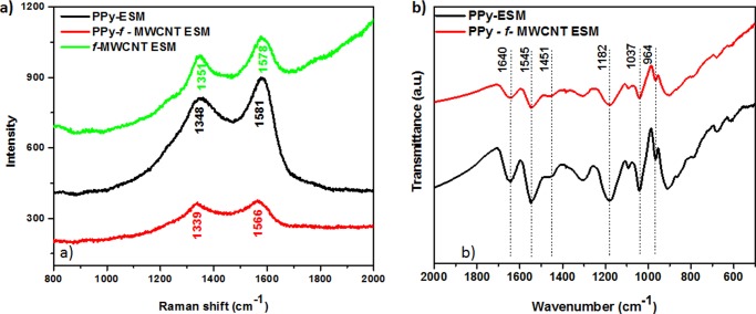
The presence of CNT, PPy, and CNT/PPy on the ESM structure was confirmed by Raman investigation (Figure 4). The corresponding f-MWCNT–ESM spectrum is characterized by a D band at 1351 cm–1 and a G band (associated with the tangential vibration modes) at 1578 cm–1. The response of the PPy–ESM sample is evidenced by the presence of peaks at 1348 cm–1 (due to the ring-stretching vibration) and 1581 cm–1 (which corresponds to the −C=C stretching vibration of the PPy backbone).56−58 It should be noted that the wavelengths of these latter peaks are higher than those of the corresponding absorptions for the PPy–f-MWCNT–ESM system (1339 and 1566 cm–1, respectively). The shift in the position of these peaks is associated with the longer conjugation length of the resulting polymeric chains,59 an evidence that a material with superior electrical response results from the CNTs/PPy interaction. The Fourier transform infrared (FTIR) spectrum shown in Figure 4b allows a better identification of the contributions from the two components. The peak at 1545 cm–1 corresponds to the stretching vibration of C=C of PPy, whereas the vibration corresponding to the C–N bond of PPy60−62 can be seen at 1456/1189 cm–1. The peaks at 1037 and 964 cm–1 are assigned to the C–H in-plane vibration band and the in-plane bending of Py,63 respectively. The additional peak identified at 1640 cm–1 characterizes the presence of amide I, a component of the ESM collagen.64
Figure 4.
Raman spectra of samples f-MWCNT–ESM, PPy–ESM, and PPy–f-MWCNT–ESM (a) and FTIR spectra of samples PPy–ESM and PPy–f-MWCNT–ESM ([Py] = 0.05 M).
2.2. Electrochemical Characterization of the Devices
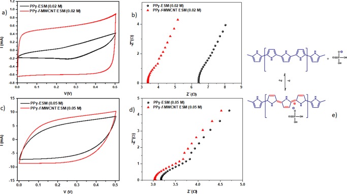
The presence of CNTs affects the electrochemical behavior of the resulting device in terms of its transport and polarization characteristics. We compared the C–V curves and impedance spectra of the samples prepared in both the absence and presence of CNTs using different concentrations of Py. The corresponding voltammograms and R–X diagrams, which are shown in Figure 5, provide relevant information about the influence of the additives used (CNT and PPy) on the overall response of the device.
Figure 5.
Comparison of voltammograms of samples PPy–ESM and PPy–f-MWCNT–ESM using 0.02 M of Py (a) and 0.05 M (c) at scan rate of 50 mV/s and corresponding impedance spectrum using 0.02 M (b) and 0.05 M (d) and corresponding scheme for charge storage mechanism of CNT/PPy in H3PO4/PVA electrolyte (e).
Comparing the C–V curves, it is possible to identify that the presence of CNT improves the electrochemical performance of the device (because the specific capacitance is proportional to the area enclosed by the curve)—particularly in terms of the maximum current observed and the more rectangular curve shape, typical of an electric double-layer capacitor signature. Examining Figure 5a,c, one can see that the CNT influence is stronger for the sample prepared using a lower Py concentration (0.02 M). As a consequence, the competition established between PPy and CNT tends in favor of the CNT behavior at a lower concentration of the conducting polymer, as expected. On the other hand, as shown in Figure 5c, minimal change in the C–V is observed for samples prepared using a high concentration of the conducting polymer, confirming that the good coverage provided by PPy (as shown in the SEM images) results in a higher level of conductivity and a lower CNT relative contribution on the overall response.
The more rectangular shape of the C–V curves for the samples containing f-MWCNT suggests a capacitive behavior.65 However, the corresponding C–V curves for PPy–f-MWCNT–ESM have become more prolate (“cone-shaped”) due to the presence of the incorporated PPy chains,66 as shown in Figure 5c.
Examining the impedance (Figure 5b,d), one can observe that the samples containing CNTs exhibit superior electrical properties: the intersection of Z″ with the x axis (which corresponds to the bulk resistance value) is lower for samples in which f-MWCNTs are present, irrespective of the Py concentration used. However, this difference in the electrical response between samples prepared in the absence and presence of f-MWCNT is minimized in the case of a higher PPy content (Figure 5d).
These effects contribute to the reduction in the IR drop (i.e., the negligible voltage drop associated with the internal resistance of the sample), which is of the order of 3 Ω for the PPy−f-MWCNT−ESM samples. This characterizes a material with a superior electrical performance (such as fast charge accumulation) that can be associated to a low resistance for charge circulation and piling up at the electrodes.
In Figure 5e, we present a schematic view of the charge storage process occurring in the CNT/PPy samples in the presence of H3PO4/PVA: as H3PO4 is dissociated into H+ and H2PO4– in the gel (the latter thus becoming the dominant species), when PPy is p-doped for the first time, the Cl– anions are replaced by H2PO4– counter ions to balance the charge. To better investigate the (faradic or nonfaradic) storage mechanisms that prevail in the absence/presence of CNTs, we examined the variation in the maximum current observed in the C–V curves with the scan rate υ, by assuming the relationship
| 1 |
where C is a parameter that depends on the electrode area and on the intrinsic properties of the device, whereas b is associated with the specific dominant mechanism for charge accumulation. In particular, b = 1 characterizes a surface-limited process in which both double layer charging and pseudocapacitive behavior are dominant, whereas b = 0.5 characterizes a diffusion process.9 The value of b can be obtained from the slope of the log(I) versus log(scan rate) curve. In Figure 6, we present the corresponding curves for the samples of interest. As one can see, a stronger variation in the b value is observed for samples prepared in the presence of a lower concentration of Py (0.02 M), with a smaller slope (0.55) being found for the sample prepared by direct PPy deposition on the supporting ESM, wherein a diffusion-dependent process is favored.
Figure 6.
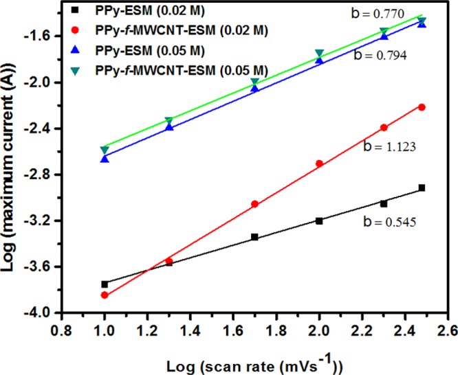
Dependence of current I(V) as a function of different scan rate for samples PPy–ESM and PPy–f-MWCNT–ESM (0.02 and 0.05 M).
Hence, a capacitive surface process is dominant for the sample in which CNTs are incorporated on the ESM before the PPy deposition, with a slope value of the order of 1. However, the slope is essentially the same for the samples prepared in the presence of a larger Py concentration (0.05 M), irrespective of whether the CNTs are present or not, indicating that a larger amount of incorporated PPy dampens the CNT contribution to the charge storage mechanism of diffusion-controlled and capacitive-controlled processes. Thus, in this case, the overall process tends to be dominated by mixed diffusion-controlled and capacitive mechanisms, and the slope of the curves is 0.77, a value that can be associated with an increase in the CD current, characterizing the superior electrical properties of PPy–f-MWCNT–ESM-based electrodes. For comparison, we fabricated a SC based only on f-MWCNT–ESM. For these SCs, as determined from the C–V diagram (Figure S3a), due to the high impedance (Figure S3b), a negligible capacitance is a strong indication that the electrochemical properties of the ESM-based SCs are in fact critically dependent on the presence of the conducting polymer.
2.3. Optimization of Charge Storage Mechanisms
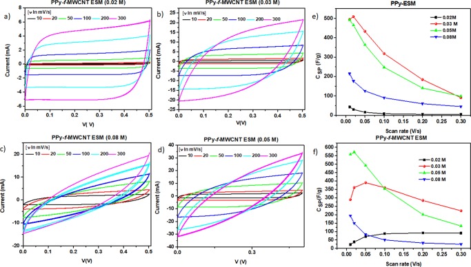
The previous results indicate that PPy/CNTs composites are an essential component of flexible SCs based on the ESM support because of the capacitive processes occurring in the mesoporous structure of the covered membrane and the improved electrical properties (as revealed by impedance spectra measurements). In addition, the relative amount of incorporated PPy also plays a role in determining the characteristics of the final device. As observed, although the capacitive properties of CNTs are evident at low PPy concentration, a diffusion-controlled behavior takes place with increasing concentration of the conducting polymer. As result of the competition established between capacitive and diffusion-dependent processes, one can explore the existence of an “optimum” PPy–f-MWCNT relative concentration at which both properties would be ideally balanced. In this direction, we have prepared SCs of PPy–f-MWCNT–ESM, wherein the Py concentration was varied in the 0.02–0.08 M range. The corresponding cyclic voltammograms are shown in Figure 7, where it is possible to identify the general trend of an increase in the current with the increment in the scan voltage ratio.
Figure 7.
Dependence of current I(V) as function of different scan rate for PPy–f-MWCNT–ESM (0.02 M (a), 0.03 M (b), 0.05 M (c), and 0.08 M (d)) and specific capacitance for different scan rate for PPy–ESM (e) and PPy–f-MWCNT–ESM (f).
Note that at lower scan rate, the curves obtained for all the samples present a rectangular shape that is progressively modified to a more oblate form as the scan rate is increased.4 This change is more evident for the samples prepared in the presence of a higher amount of PPy; hence, one can expect that the ESM SC capacitive behavior tends to be progressively affected once the concentration of incorporated conducting polymer reaches a critical range.
As a general behavior, the specific capacitance tends to be strongly affected by changes in the scan rate due to the characteristic time for ion migration in the material. As the scan rate increases, there is a progressive reduction in the ion concentration on the surface of the electrodes, defining the existence of a limiting mass transfer step, which leads to a decrease in the specific capacitance. On the other hand, the highly conductive supports allow an efficient access for electrons and ions, facilitating the occurrence of fast redox reactions at higher scan rates. As one can see in Figure 7e, the general behavior of the samples prepared using pristine PPy is to exhibit a diminishing specific capacitance as the scan rate increases. At a relatively low polymer concentration, the PPy/CNT samples typically present an increase in the capacitance (see Figure 7f) due to the prevalence of the highly conductive CNTs/PPy nanofibrous structure. This behavior changes as the polymer concentration increases and the contribution of redox processes becomes favored. It is worth noting that in the absence of CNT and an increase in the Py concentration, the best performance is attained in samples containing 0.03 M, as shown in Figure 7e: the fast decrease in the capacitance with the scan rate variation at a higher Py concentration (0.05 M) is an evidence that the presence of PPy in high enough concentrations contributes to the inhibition of charge separation, with a consequent decrease in the overall efficiency of the charge transport and separation. On the other hand, the best performance of the samples prepared in the presence of PPy/CNT is obtained when using the intermediate Py concentration (0.05 M), whereas the behavior of the samples with a lower polymer content indicates that the high conductivity of the support leads to an increasing capacitance at higher scan rates.67 When analyzing the data presented in Figure 7, one can see as a general feature that for equivalent values of the scan rate and voltage, the maximum value attained by the current initially increases with the relative amount of incorporated PPy, an indication of a progressive improvement in the electrochemical properties of the devices. However, the maximum value of the current becomes smaller for the sample prepared with the highest Py concentration (0.08 M), whose C–V curve presents a more accentuated cone shape, characterizing a limiting condition for electrochemical performance of the device.
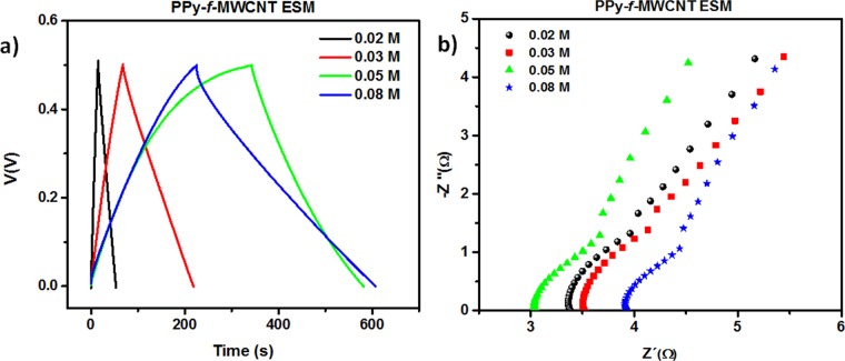
In addition, we performed CD experiments using a fixed 0.5/–0.5 mA current level, with an applied potential in the 0.0–0.5 V range (Figure 8a). As one can see, the total time taken to complete a CD cycle initially increases with the amount of PPy incorporated into the device, but a smaller time is registered for the 0.08 M sample due to the reduction in the available sites for charge distribution and accumulation. For all curves, the typical value of the IR drop signature (i.e., the abrupt change in the CD curve in the transition from charge-to-discharge process) is negligible, a fact that can be associated with the contribution of the CNTs for the electrical properties of the template (lower internal resistance). This result is consistent with the information gathered from both the morphological analysis and the corresponding voltammograms.
Figure 8.
(a) CD curves for samples of PPy–f-MWCNT–ESM at increasing PPy concentration. (b) R–X diagram of the corresponding samples.
As for the electrical properties, as shown in Figure 8b for 0.02, 0.03, and 0.05 M samples, the bulk resistance is of the order of 3 Ω, with an increase to the 4 Ω range being verified for the sample containing 0.08 M Py. The minimal variation in the bulk resistance of sample indicates that PPy introduces improved electrical properties for the sample in the explored concentration range. To examine this in more detail, we summarized in Table 1 the capacitances of the resulting devices based on the PPy active layer (PPy weight) and whole weight (gravimetric capacitance), area (CA), and volume (Cv) at a current density of 0.5 mA/cm2 (the corresponding equations are described in the Supporting Information).
Table 1. Comparison of Capacitances of PPy–f-MWCNT–ESM at Increasing PPy Concentration.
| Py concentration (M) | CSP active layer (F/g) | CSP whole device (F/g) | CA (mF/cm2) | CV (F/cm3) |
|---|---|---|---|---|
| 0.02 | 134.2 | 43.0 | 87.5 | 4.3 |
| 0.03 | 384.2 | 122.8 | 249.0 | 9.6 |
| 0.05 | 357.9 | 153.2 | 369.5 | 15.7 |
| 0.08 | 224.3 | 155.0 | 546.5 | 24.8 |
The specific capacitance (Csp) of the active material, which goes through a maximum of 384.2 F/g for the sample prepared using a 0.03 M Py solution, decreases when the PPy content is further increased (224.3 F/g for the 0.08 M sample). A different behavior is observed for the capacitance of the whole device (i.e., when an ESM layer is present), which reaches a saturating value close to 153 F/g when Py concentrations equal or above 0.05 M were used. As for the areal CA and volumetric (Cv) capacitance, both increase with an increment in the polymer content, with the devices prepared using a 0.08 M Py solution exhibiting the highest values (546.5 mF/cm2 and 24.8 F/cm3, respectively). Hence, considering these results and after analyzing the corresponding mechanical resistance of the samples, we suggest that the use of 0.05 M Py solutions offers the best compromise between good electrochemical properties and adequate flexibility, which would result in an optimized device performance.
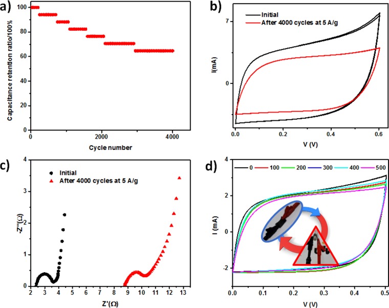
Indeed, important functional characteristics to be considered in the design of usable SCs are their capacitance retention and bending resistance, which are essential requirements for their practical use in long-life flexible storage devices. For investigating the retention capacity of 0.05 M PPy–f-MWCNT–ESM SCs, we performed successive CD cycles in which the current was varied in the 5 to −5 A/g range. The observed variation in the specific capacitance is shown in Figure 9a.
Figure 9.
(a) Capacitance retention of PPy–f-MWCNT–ESM samples (PPy 0.05 M), (b) influence of the cycling degradation of the corresponding C–V diagram, (c) corresponding R–X diagrams for pristine and degraded samples, and (d) C–V diagrams of devices after 500 cycles of bending.
The “aging” of the devices can be determined by examining the changes in their C–V curve along this CD process. At first, one can expect that it should occur at an interfacial exchange of anions between the polymer and the phosphate-based electrolyte due to the initial difference in the corresponding concentrations. After an equilibrium condition is reached, a typical profile of degradation begins to be observed. The continuous use of the device returns values for the capacitance retention of the order of 60% after 4000 test cycles (Figure 9a), a value that compares favorably relative to those of SCs based on PPy immersed in liquid electrolytes.45 Corresponding C–V curves at 50 mV/s (shown in Figure 9b) reveal the resulting degradation after 4000 cycles at 5 A/g. The impedance data (shown in Figure 9c) reveal that aging induces an increase in the internal resistance of the samples, confirming the degradation identified in the C–V curves.
In addition to testing the mechanical flexibility and performance resistance of the devices after repeated folding and unfolding cycles, we examined the possible degrading of their electrochemical characteristics after successive treatment with bending assays. As shown in Figure 9d, the voltammogram of the 0.05 M PPy–f-MWCNT–ESM device remains essentially the same after repeated mechanical assays, with no detectable change in the prevailing charge storage mechanisms. In this manner, the 0.05 M PPy–f-MWCNT–ESM device complies with a stringent requirement for the practical use of flexible SCs.
One could observe that the specific capacitance of a device, a defining characteristic of its performance, usually exhibits a strong dependence on the adopted electrochemical setup (e.g., whether a two- or three-electrode configuration is adopted, or a solid or liquid electrolyte is used), operating scan rate, and applied current density. As a consequence, when evaluating different experimental systems, one should be careful in taking adequate balance of these critical parameters. In Table 2, we compare the overall characteristics of the 0.05 and 0.08 M PPy–f-MWCNT–ESMs, such as their specific areal and volumetric and gravimetric capacitances, to those of similar SCs recently discussed in the literature. As one can observe, the 0.08 M bioinspired SC introduced in the present work shows both areal and gravimetric capacitances that are higher than those of other flexible devices based on templates composed by pure conducting materials (such as graphene68,69 or CNTs70,71). The value for its volumetric capacitance C–V is only surpassed by that of the device produced with a thick poly(3,4-ethylenedioxythiophene) (PEDOT)–poly(styrene sulfonate) (PSS)–graphene layer, in which the amount of active material present is greater and which operates at a higher potential window. It is an additional noteworthy point that superior results were obtained for the PPY–f-MWCNT–ESM devices when operating under more moderate conditions, viz., low voltage window and low current density; a lesser degradation should accompany its repeated operation under this situation, allowing for an increase in the lifetime of the corresponding device.
Table 2. Comparison of Capacitances of PPy–f-MWCNT–ESM with Those of Other Reported Devices in the Literature.
| device | CSP whole device (F/g) | CV (F/cm3) | CA (mF/cm2) | potential window (V) | electrolyte | I (mA/cm2) | ref |
|---|---|---|---|---|---|---|---|
| graphene/MoS2 | N/A | 19.4 | 70 | 0–0.8 | H2SO4/PVA | 0.3 | (72) |
| reduced graphene oxide/PPy/cellulose | N/A | 8.5 | 510 | 0–0.8 | H3PO4/PVA | 0.1 | (9) |
| PPy-filter paper | N/A | N/A | 420 | 0–0.8 | H3PO4/PVA | 1.0 | (11) |
| PEDOT–CNT | 13.4 | 18.0 | 354 | 0–1.2 | LiCl/PVA | 1.0 | (70) |
| graphene–PEDOT/PSS | 52.7 | 49.9 | 448 | 0–1.0 | H3PO4/PVA | 10 mV/s | (69) |
| CNT/polyaniline hydrogel | N/A | N/A | 184 | –0.2 to 0.7 | H2SO4/PVA | 1.0 | (71) |
| PPy–f-MWCNT–ESM 0.05 M | 153.2 | 15.7 | 370 | 0–0.5 | H3PO4/PVA | 0.5 | this work |
In summary, the PPy–f-MWCNT–ESM SCs discussed here appear as promising bioinspired devices, with competitive operational performance if one considers the high values of their areal and volumetric and gravimetric capacitive characteristics. One should observe that these SCs were prepared using a widely available resource usually classified as a waste material, an additional comparative advantage for their possible use as a highly efficient and cost-effective alternative for the design of flexible energy storage devices.
3. Conclusions
We have examined the use of ESM, a usually discarded material of biological origin, as a template for the development of flexible solid-state SCs through the successive incorporation of CNTs and PPy. These hybrid devices have shown promising operational characteristics in terms of cyclability, electrochemical behavior, mechanical flexibility, and production costs. The comparison of their performance parameters with those of similar devices discussed in the literature places the PPy–f-MWCNT–ESM SCs in the frontier of highly efficient energy storage devices, with the additional advantage of combining low production cost with ecofriendly processing. In fact, the ESM macroporous structure can be exploited not only in applications involving conducting polymers, but it could also be used as a general platform for the assembly of metallic nanoparticles, carbon nanostructures, metal oxides, among others.
In summary, our results indicate that ESM porous structure can be considered as a binder-free and sustainable natural product with promising possibilities of application in energy storage devices due to its characteristic stability, flexibility, low cost, and large availability of sites for the incorporation of additives.
4. Experimental Section
4.1. Materials
All eggs used were purchased from the local market (Juazeiro, Brazil). Py, ferric chloride (FeCl3), MWCNT (diameter of 6–9 nm × length of 5 μm), and PVA (MW 86–145 kDa) were acquired from Sigma-Aldrich. H3PO4, ethanol, nitric acid (HNO3), and hydrochloric acid (HCl) were obtained from the Brazilian companies Sigma-Vetec, Dinâmica, and Êxodo Científica, respectively. All of the chemicals were of analytical grade and used as received, except for Py, which was distilled twice under reduced pressure before use. The ultrahigh purity water employed in all of the experiments was obtained from a Millipore water system.
4.2. ESM Etching
After being broken and drained, the fresh eggshells were washed several times with deionized water until complete removal of the yolk and albumen residues. They were then placed in a 1 M HCl solution for 2 h under constant stirring. Subsequently, the ESM was manually removed and washed several times in an acidic solution, until complete removal of CaCO3. Finally, the ESMs were removed from the acid solution and washed several times with deionized water until neutral pH was obtained.
4.3. MWCNT Assembly on ESM
First, the MWCNTs were functionalized by refluxing them in a 1:3 HCl/HNO3 acidic mixture at 130 °C for 5 h. After allowing to cool at room temperature, the MWCNT suspension was vacuum filtered and washed with generous amounts of deionized water until the drained liquid had a pH of ∼7. Finally, the f-MWCNTs were dried at room conditions for 24 h. To assemble the f-MWCNT on the ESM fibers, rectangular pieces of ESM were immersed in a 0.1 mg/mL f-MWCNT ethanol dispersion and sonicated during three consecutive periods of 30 min, which were intercalated by rinsing with deionized water (due to the characteristic porosity degree of support, the required diffusion of CNTs into the structure is favored by ultrasonic dispersion, which can be considered49 as a high-energy process for CNT incorporation). Finally, the resulting f-MWCNT–ESMs were rinsed several times with deionized water to remove unattached nanotubes and then dried at room temperature.
4.4. Py Polymerization on ESM and f-MWCNT–ESM
We coated both pristine ESMs and f-MWCNT–ESMs with layers of PPy through an in situ chemical polymerization using a 1:1 monomer-to-oxidant ratio. First, the sample of interest (ESM or f-MWCNT–ESM) was immersed in 25 mL of a precooled 1 M HCl solution containing an equivalent amount of Py (0.02, 0.03, 0.05, and 0.08 M) at 5 °C, which was stirred for 30 min. Then, 25 mL of solution of FeCl3 solution (1:1 oxidant-to-monomer ratio) in 1 M of HCl with a corresponding concentration of monomer (0.02, 0.03, 0.05, and 0.08 M) was added in a dropwise manner, with the complete polymerization being allowed to occur for 2 h at 5 °C. Finally, the modified samples (PPy–ESM or PPy–f-MWCNT–ESM) were washed several times with deionized water and kept in deionized water until use.
4.5. Fabrication of PPy–ESM and PPy–f-MWCNT–ESM Semisolid State Symmetric SCs
An aqueous PVA–H3PO4 gel electrolyte was prepared by dissolving 10% w/v of PVA in deionized water at 85 °C, with the resulting suspension being maintained under constant stirring until becoming clear. Subsequently, H3PO4 (10 mL of 85 wt % in aqueous solution) was introduced and the solution vigorously stirred for 30 min. After cooling, the solution was cast on a metal plate covered with parafilm and allowed to dry for 24 h at room temperature at a relative humidity of 35% to form a thin membrane. To assemble the SC, two 1 cm2 square pieces of PPy–ESM or PPy–f-MWCNT–ESM that will serve as electrodes were immersed in a 10% w/v H3PO4 aqueous solution for 10 min. Finally, when the electrodes were removed from the solution and the excess humidity wiped, a PVA–H3PO4 membrane was sandwiched between them under a transversally established pressure of 10 N/cm2.
4.6. Characterization Techniques
We have used SEM to characterize the morphological features of all samples by employing a FEG-SEM MIRA 3 (Tescan, Czech Republic). Due to the high electrical conductivity of the samples, no previous metal-sputtering treatment was necessary (except for the pure ESM, where a fine gold layer was deposited). Raman spectra were obtained in the 800–2000 cm–1 region by using a microscopic confocal Raman spectrometer (LabRAM Aramis; HORIBA Jobin Yvon, France), with a 633 nm He–Ne laser. The electrochemical testing of the prototype symmetric SCs was carried in a two-electrode configuration. The devices were mounted in a Solartron 12962A sample holder between two carbon cloth electrodes. All electrochemical (cyclic voltammetry, galvanostatic CD, and electrochemical impedance) measurements were carried out at room temperature using Autolab PGSTAT302N (Metrohm, Switzerland). FTIR measurements were performed using the KBr method in IR Prestige-21 Fourier Transform Infra-Red Spectrometer (Shimadzu, Japan).
Acknowledgments
This work was partially supported by INFO INCT Institute and the Brazilian agencies FINEP, CAPES, FAPESB, FACEPE, and CNPq. J.J.A.-E. would like to thank CNPq and FACEPE for a postdoctoral fellowship. The authors would like to thank Romário da Silva (UFPE) for his help in acquiring the SEM images.
Supporting Information Available
The Supporting Information is available free of charge on the ACS Publications website at DOI: 10.1021/acsomega.7b00329.
Mass density of active material deposited on ESM membrane; SEM low-magnification images of PPy–ESM and PPy–f-MWCNT–ESM surface; C–V and R–X diagrams of a flexible f-MWCNT–ESM SC; SC calculations (PDF)
(PDF)
The authors declare no competing financial interest.
Supplementary Material
References
- Winter M.; Brodd R. J. What are batteries, fuel cells, and supercapacitors?. Chem. Rev. 2004, 104, 4245–4270. 10.1021/cr020730k. [DOI] [PubMed] [Google Scholar]
- Simon P.; Gogotsi Y. Materials for electrochemical capacitors. Nat. Mater. 2008, 7, 845–854. 10.1038/nmat2297. [DOI] [PubMed] [Google Scholar]
- Miller J. R.; Simon P. Electrochemical capacitors for energy management. Science 2008, 321, 651–652. 10.1126/science.1158736. [DOI] [PubMed] [Google Scholar]
- Wang J.-G.; Yang Y.; Huang Z.-H.; Kang F. Rational synthesis of MnO2/conducting polypyrrole@carbon nanofiber triaxial nano-cables for high-performance supercapacitors. J. Mater. Chem. 2012, 22, 16943–16949. 10.1039/c2jm33364c. [DOI] [Google Scholar]
- Wang J.-G.; Kang F.; Wei B. Engineering of MnO2-based nanocomposites for high-performance supercapacitors. Prog. Mater. Sci. 2015, 74, 51–124. 10.1016/j.pmatsci.2015.04.003. [DOI] [Google Scholar]
- Zhan Y.; Mei Y.; Zheng L. Materials capability and device performance in flexible electronics for the Internet of Things. J. Mater. Chem. C 2014, 2, 1220–1232. 10.1039/C3TC31765J. [DOI] [Google Scholar]
- Zeng W.; Shu L.; Li Q.; Chen S.; Wang F.; Tao X. M. Fiber-based wearable electronics: a review of materials, fabrication, devices, and applications. Adv. Mater. 2014, 26, 5310–5336. 10.1002/adma.201400633. [DOI] [PubMed] [Google Scholar]
- Teo W.-E.; Ramakrishna S. Electrospun nanofibers as a platform for multifunctional, hierarchically organized nanocomposite. Compos. Sci. Technol. 2009, 69, 1804–1817. 10.1016/j.compscitech.2009.04.015. [DOI] [Google Scholar]
- Wan C.; Jiao Y.; Li J. Flexible, highly conductive, and free-standing reduced graphene oxide/polypyrrole/cellulose hybrid papers for supercapacitor electrodes. J. Mater. Chem. A 2017, 5, 3819–3831. 10.1039/C6TA04844G. [DOI] [Google Scholar]
- Ge D.; Yang L.; Fan L.; Zhang C.; Xiao X.; Gogotsi Y.; Yang S. Foldable supercapacitors from triple networks of macroporous cellulose fibers, single-walled carbon nanotubes and polyaniline nanoribbons. Nano Energy 2015, 11, 568–578. 10.1016/j.nanoen.2014.11.023. [DOI] [Google Scholar]
- Yuan L.; Yao B.; Hu B.; Huo K.; Chen W.; Zhou J. Polypyrrole-coated paper for flexible solid-state energy storage. Energy Environ. Sci. 2013, 6, 470–476. 10.1039/c2ee23977a. [DOI] [Google Scholar]
- Wang F.; Kim H.-J.; Park S.; Kee C.-D.; Kim S.-J.; Oh I.-K. Bendable and flexible supercapacitor based on polypyrrole-coated bacterial cellulose core-shell composite network. Compos. Sci. Technol. 2016, 128, 33–40. 10.1016/j.compscitech.2016.03.012. [DOI] [Google Scholar]
- Wang X.; Kong D.; Zhang Y.; Wang B.; Li X.; Qiu T.; Song Q.; Ning J.; Song Y.; Zhi L. All-biomaterial supercapacitor derived from bacterial cellulose. Nanoscale 2016, 8, 9146–9150. 10.1039/C6NR01485B. [DOI] [PubMed] [Google Scholar]
- Liu R.; Ma L.; Huang S.; Mei J.; Xu J.; Yuan G. A flexible polyaniline/graphene/bacterial cellulose supercapacitor electrode. New J. Chem. 2017, 41, 857–864. 10.1039/C6NJ03107B. [DOI] [Google Scholar]
- Zhu L.; Wu L.; Sun Y.; Li M.; Xu J.; Bai Z.; Liang G.; Liu L.; Fang D.; Xu W. Cotton fabrics coated with lignosulfonate-doped polypyrrole for flexible supercapacitor electrodes. RSC Adv. 2014, 4, 6261–6266. 10.1039/c3ra47224h. [DOI] [Google Scholar]
- Liu L.; Weng W.; Zhang J.; Cheng X.; Liu N.; Yang J.; Ding X. Flexible supercapacitor with a record high areal specific capacitance based on a tuned porous fabric. J. Mater. Chem. A 2016, 4, 12981–12986. 10.1039/C6TA04911G. [DOI] [Google Scholar]
- Huang S.; Chen P.; Lin W.; Lyu S.; Chen G.; Yin X.; Chen W. Electrodeposition of polypyrrole on carbon nanotube-coated cotton fabrics for all-solid flexible supercapacitor electrodes. RSC Adv. 2016, 6, 13359–13364. 10.1039/C5RA24214B. [DOI] [Google Scholar]
- Zhao C.; Shu K.; Wang C.; Gambhir S.; Wallace G. G. Reduced graphene oxide and polypyrrole/reduced graphene oxide composite coated stretchable fabric electrodes for supercapacitor application. Electrochim. Acta 2015, 172, 12–19. 10.1016/j.electacta.2015.05.019. [DOI] [Google Scholar]
- Miao F.; Shao C.; Li X.; Lu N.; Wang K.; Zhang X.; Liu Y. Flexible solid-state supercapacitors based on freestanding electrodes of electrospun polyacrylonitrile@polyaniline core-shell nanofibers. Electrochim. Acta 2015, 176, 293–300. 10.1016/j.electacta.2015.06.141. [DOI] [Google Scholar]
- Liang J.; Su S.; Fang X.; Wang D.; Xu S. Electrospun fibrous electrodes with tunable microstructure made of polyaniline/multi-walled carbon nanotube suspension for all-solid-state supercapacitors. Mater. Sci. Eng., B 2016, 211, 61–66. 10.1016/j.mseb.2016.04.014. [DOI] [Google Scholar]
- Park S.; Choi K. S.; Lee D.; Kim D.; Lim K. T.; Lee K.-H.; Seonwoo H.; Kim J. Eggshell membrane: Review and impact on engineering. Biosyst. Eng. 2016, 151, 446–463. 10.1016/j.biosystemseng.2016.10.014. [DOI] [Google Scholar]
- Baláž M. Eggshell membrane biomaterial as a platform for applications in materials science. Acta Biomater. 2014, 10, 3827–3843. 10.1016/j.actbio.2014.03.020. [DOI] [PubMed] [Google Scholar]
- Nakano T.; Ikawa N.; Ozimek L. Chemical composition of chicken eggshell and shell membranes. Poult. Sci. 2003, 82, 510–514. 10.1093/ps/82.3.510. [DOI] [PubMed] [Google Scholar]
- Wei Z.; Xu C.; Li B. Application of waste eggshell as low-cost solid catalyst for biodiesel production. Bioresour. Technol. 2009, 100, 2883–2885. 10.1016/j.biortech.2008.12.039. [DOI] [PubMed] [Google Scholar]
- Mohammad-Rezaei R.; Razmi H.; Dehgan-Reyhan S. Preparation of graphene oxide doped eggshell membrane bioplatform modified Prussian blue nanoparticles as a sensitive hydrogen peroxide sensor. Colloids Surf., B 2014, 118, 188–193. 10.1016/j.colsurfb.2014.01.020. [DOI] [PubMed] [Google Scholar]
- Liu W.; Wu H.; Li B.; Dong C.; Choi M. M.; Shuang S. Immobilization of platinum nanoparticles and glucose oxidase on eggshell membrane for glucose detection. Anal. Methods 2013, 5, 5154–5160. 10.1039/c3ay40327k. [DOI] [Google Scholar]
- Gao Y.; Li X.; Gong J.; Fan B.; Su Z.; Qu L. Polyaniline nanotubes prepared using fiber mats membrane as the template and their gas-response behavior. J. Phys. Chem. C 2008, 112, 8215–8222. 10.1021/jp711601f. [DOI] [Google Scholar]
- Liu B.; Huang Y. Polyethyleneimine modified eggshell membrane as a novel biosorbent for adsorption and detoxification of Cr (VI) from water. J. Mater. Chem. 2011, 21, 17413–17418. 10.1039/c1jm12329g. [DOI] [Google Scholar]
- Guo X.; Zhang F.; Peng Q.; Xu S.; Lei X.; Evans D. G.; Duan X. Layered double hydroxide/eggshell membrane: An inorganic biocomposite membrane as an efficient adsorbent for Cr (VI) removal. Chem. Eng. J. 2011, 166, 81–87. 10.1016/j.cej.2010.10.010. [DOI] [Google Scholar]
- Liang M.; Su R.; Huang R.; Qi W.; Yu Y.; Wang L.; He Z. Facile in situ synthesis of silver nanoparticles on procyanidin-grafted eggshell membrane and their catalytic properties. ACS Appl. Mater. Interfaces 2014, 6, 4638–4649. 10.1021/am500665p. [DOI] [PubMed] [Google Scholar]
- Liu J.-K.; Luo C.-X.; Wang J.-D.; Yang X.-H.; Zhong X.-H. Controlled synthesis of silver phosphate crystals with high photocatalytic activity and bacteriostatic activity. CrystEngComm 2012, 14, 8714–8721. 10.1039/c2ce25604e. [DOI] [Google Scholar]
- Mallampati R.; Valiyaveettil S. Eggshell membrane-supported recyclable catalytic noble metal nanoparticles for organic reactions. ACS Sustainable Chem. Eng. 2014, 2, 855–859. 10.1021/sc4004899. [DOI] [Google Scholar]
- Tang Q.; Wu J.; Tang Z.; Li Y.; Lin J.; Huang M. Flexible and macroporous network-structured catalysts composed of conducting polymers and Pt/Ag with high electrocatalytic activity for methanol oxidation. J. Mater. Chem. 2011, 21, 13354–13364. 10.1039/c1jm11857a. [DOI] [Google Scholar]
- Ma M.; You S.; Qu J.; Ren N. Natural eggshell membrane as separator for improved coulombic efficiency in air-cathode microbial fuel cells. RSC Adv. 2016, 6, 66147–66151. 10.1039/C6RA13052F. [DOI] [Google Scholar]
- Dong D.; Wu Y.; Zhang X.; Yao J.; Huang Y.; Li D.; Li C.-Z.; Wang H. Eggshell membrane-templated synthesis of highly crystalline perovskite ceramics for solid oxide fuel cells. J. Mater. Chem. 2011, 21, 1028–1032. 10.1039/C0JM03061A. [DOI] [Google Scholar]
- Chung S.-H.; Manthiram A. Eggshell membrane-derived polysulfide absorbents for highly stable and reversible lithium–sulfur cells. ACS Sustainable Chem. Eng. 2014, 2, 2248–2252. 10.1021/sc500452j. [DOI] [Google Scholar]
- Meng X.; Deng D. Trash to treasure: Waste eggshells used as reactor and template for synthesis of Co9S8 nanorod arrays on carbon fibers for energy storage. Chem. Mater. 2016, 28, 3897–3904. 10.1021/acs.chemmater.6b01142. [DOI] [Google Scholar]
- Li Z.; Zhang L.; Amirkhiz B. S.; Tan X.; Xu Z.; Wang H.; Olsen B. C.; Holt C.; Mitlin D. Carbonized Chicken Eggshell Membranes with 3D Architectures as High-Performance Electrode Materials for Supercapacitors. Adv. Energy Mater. 2012, 2, 431–437. 10.1002/aenm.201100548. [DOI] [Google Scholar]
- Geng J.; Wu H.; Al-Enizi A. M.; Elzatahry A. A.; Zheng G. F. Freestanding eggshell membrane-based electrodes for high-performance supercapacitors and oxygen evolution reaction. Nanoscale 2015, 7, 14378–14384. 10.1039/C5NR04603C. [DOI] [PubMed] [Google Scholar]
- Yu H. J.; Tang Q. Q.; Wu J. H.; Lin Y. Z.; Fan L. Q.; Huang M. L.; Lin J. M.; Li Y.; Yu F. D. Using eggshell membrane as a separator in supercapacitor. J. Power Sources 2012, 206, 463–468. 10.1016/j.jpowsour.2012.01.116. [DOI] [Google Scholar]
- Liu X.; Yin C.; Yang J.; Liang M.; Wei J.; Zhang Z.; Wang H.; Wang Q. Controllable preparation of an eggshell membrane supported hydrogel electrolyte with thickness-dependent electrochemical performance. J. Mater. Chem. A 2016, 4, 17933–17938. 10.1039/C6TA07341G. [DOI] [Google Scholar]
- Ji H.; Zhao X.; Qiao Z.; Jung J.; Zhu Y.; Lu Y.; Zhang L. L.; MacDonald A. H.; Ruoff R. S. Capacitance of carbon-based electrical double-layer capacitors. Nat. Commun. 2014, 5, 3317 10.1038/ncomms4317. [DOI] [PubMed] [Google Scholar]
- Ramya R.; Sivasubramanian R.; Sangaranarayanan M. Conducting polymers-based electrochemical supercapacitors—progress and prospects. Electrochim. Acta 2013, 101, 109–129. 10.1016/j.electacta.2012.09.116. [DOI] [Google Scholar]
- de Oliveira H. P.; Sydlik S. A.; Swager T. M. Supercapacitors from Free-Standing Polypyrrole/Graphene Nanocomposites. J. Phys. Chem. C 2013, 117, 10270–10276. 10.1021/jp400344u. [DOI] [Google Scholar]
- de Oliveira A. H. P.; de Oliveira H. P. Carbon nanotube/polypyrrole nanofibers core-shell composites decorated with titanium dioxide nanoparticles for supercapacitor electrodes. J. Power Sources 2014, 268, 45–49. 10.1016/j.jpowsour.2014.06.027. [DOI] [Google Scholar]
- de Oliveira A. H. P.; Nascimento M. L. F.; de Oliveira H. P. Carbon Nanotube@MnO2@Polypyrrole Composites: Chemical Synthesis, Characterization and Application in Supercapacitors. Mater. Res. 2016, 19, 1080–1087. 10.1590/1980-5373-MR-2016-0347. [DOI] [Google Scholar]
- Peng C.; Zhang S.; Jewell D.; Chen G. Z. Carbon nanotube and conducting polymer composites for supercapacitors. Prog. Nat. Sci. 2008, 18, 777–788. 10.1016/j.pnsc.2008.03.002. [DOI] [Google Scholar]
- Torres F. G.; Troncoso O. P.; Piaggio F.; Hijar A. Structure–property relationships of a biopolymer network: The eggshell membrane. Acta Biomater. 2010, 6, 3687–3693. 10.1016/j.actbio.2010.03.014. [DOI] [PubMed] [Google Scholar]
- Lou K.; Zhu Z.; Zhang H.; Wang Y.; Wang X.; Cao J. Comprehensive studies on the nature of interaction between carboxylated multi-walled carbon nanotubes and bovine serum albumin. Chem.–Biol. Interact. 2016, 243, 54–61. 10.1016/j.cbi.2015.11.020. [DOI] [PubMed] [Google Scholar]
- Gao J.; Hu M.; Li R. K. Y. Ultrasonication induced adsorption of carbon nanotubes onto electrospun nanofibers with improved thermal and electrical performances. J. Mater. Chem. 2012, 22, 10867–10872. 10.1039/c2jm00035k. [DOI] [Google Scholar]
- Mercante L. A.; Pavinatto A.; Iwaki L. E.; Scagion V. P.; Zucolotto V.; Oliveira O. N. Jr.; Mattoso L. H.; Correa D. S. Electrospun polyamide 6/poly (allylamine hydrochloride) nanofibers functionalized with carbon nanotubes for electrochemical detection of dopamine. ACS Appl. Mater. Interfaces 2015, 7, 4784–4790. 10.1021/am508709c. [DOI] [PubMed] [Google Scholar]
- McCullough L. A.; Dufour B.; Matyjaszewski K. Polyaniline and polypyrrole templated on self-assembled acidic block copolymers. Macromolecules 2009, 42, 8129–8137. 10.1021/ma901560k. [DOI] [Google Scholar]
- Johnston J. H.; Kelly F. M.; Moraes J.; Borrmann T.; Flynn D. Conducting polymer composites with cellulose and protein fibres. Curr. Appl. Phys. 2006, 6, 587–590. 10.1016/j.cap.2005.11.067. [DOI] [Google Scholar]
- Peng C.; Jin J.; Chen G. Z. A comparative study on electrochemical co-deposition and capacitance of composite films of conducting polymers and carbon nanotubes. Electrochim. Acta 2007, 53, 525–537. 10.1016/j.electacta.2007.07.004. [DOI] [Google Scholar]
- Chen G. Z.; Shaffer M. S.; Coleby D.; Dixon G.; Zhou W.; Fray D. J.; Windle A. H. Carbon nanotube and polypyrrole composites: coating and doping. Adv. Mater. 2000, 12, 522–526. . [DOI] [Google Scholar]
- Stejskal J.; Trchova M.; Bober P.; Moravkova Z.; Kopecky D.; Vrnata M.; Prokes J.; Varga M.; Watzlova E. Polypyrrole salts and bases: superior conductivity of nanotubes and their stability towards the loss of conductivity by deprotonation. RSC Adv. 2016, 6, 88382–88391. 10.1039/C6RA19461C. [DOI] [Google Scholar]
- Bober P.; Liu J.; Mikkonen K. S.; Ihalainen P.; Pesonen M.; Plumed-Ferrer C.; von Wright A.; Lindfors T.; Xu C. L.; Latonen R. M. Biocomposites of Nanofibrillated Cellulose, Polypyrrole, and Silver Nanoparticles with Electroconductive and Antimicrobial Properties. Biomacromolecules 2014, 15, 3655–3663. 10.1021/bm500939x. [DOI] [PubMed] [Google Scholar]
- Lei Y. H.; Ohtsuka T.; Sheng N. Corrosion protection of copper by polypyrrole film studied by electrochemical impedance spectroscopy and the electrochemical quartz microbalance. Appl. Surf. Sci. 2015, 357, 1122–1132. 10.1016/j.apsusc.2015.09.053. [DOI] [Google Scholar]
- Zhong J.; Gao S.; Xue G. B.; Wang B. Study on Enhancement Mechanism of Conductivity Induced by Graphene Oxide for Polypyrrole Nanocomposites. Macromolecules 2015, 48, 1592–1597. 10.1021/ma502449k. [DOI] [Google Scholar]
- Hazarika J.; Kumar A. Controllable synthesis and characterization of polypyrrole nanoparticles in sodium dodecylsulphate (SDS) micellar solutions. Synth. Met. 2013, 175, 155–162. 10.1016/j.synthmet.2013.05.020. [DOI] [Google Scholar]
- da Silva F. A. G.; Queiroz J. C.; Macedo E. R.; Fernandes A. W. C.; Freire N. B.; da Costa M. M.; de Oliveira H. P. Antibacterial behavior of polypyrrole: The influence of morphology and additives incorporation. Mater. Sci. Eng., C 2016, 62, 317–322. 10.1016/j.msec.2016.01.067. [DOI] [PubMed] [Google Scholar]
- Wang J.-G.; Yang Y.; Huang Z.-h.; Kang F. MnO2/polypyrrole nanotubular composites: reactive template synthesis, characterization and application as superior electrode materials for high-performance supercapacitors. Electrochim. Acta 2014, 130, 642–649. 10.1016/j.electacta.2014.03.082. [DOI] [Google Scholar]
- Wang J.-G.; Wei B.; Kang F. Facile synthesis of hierarchical conducting polypyrrole nanostructures via a reactive template of MnO2 and their application in supercapacitors. RSC Adv. 2014, 4, 199–202. 10.1039/C3RA45824E. [DOI] [Google Scholar]
- Zhao Y.-H.; Chi Y.-J. Characterization of collagen from eggshell membrane. Biotechnology 2009, 8, 254–258. 10.3923/biotech.2009.254.258. [DOI] [Google Scholar]
- Dai Z.; Peng C.; Chae J. H.; Ng K. C.; Chen G. Z. Cell voltage versus electrode potential range in aqueous supercapacitors. Sci. Rep. 2015, 5, 9854 10.1038/srep09854. [DOI] [PMC free article] [PubMed] [Google Scholar]
- Wang J. P.; Xu Y. L.; Wang J.; Du X. F.; Xiao F.; Li J. B. High charge/discharge rate polypyrrole films prepared by pulse current polymerization. Synth. Met. 2010, 160, 1826–1831. 10.1016/j.synthmet.2010.06.020. [DOI] [Google Scholar]
- Lang X.; Hirata A.; Fujita T.; Chen M. Nanoporous metal/oxide hybrid electrodes for electrochemical supercapacitors. Nat. Nanotechnol. 2011, 6, 232–236. 10.1038/nnano.2011.13. [DOI] [PubMed] [Google Scholar]
- Li N.; Lv T.; Yao Y.; Li H.; Liu K.; Chen T. Compact graphene/MoS2 composite films for highly flexible and stretchable all-solid-state supercapacitors. J. Mater. Chem. A 2017, 5, 3267–3273. 10.1039/C6TA10165H. [DOI] [Google Scholar]
- Liu Y.; Weng B.; Razal J. M.; Xu Q.; Zhao C.; Hou Y.; Seyedin S.; Jalili R.; Wallace G. G.; Chen J. High-performance flexible all-solid-state supercapacitor from large free-standing graphene-PEDOT/PSS films. Sci. Rep. 2015, 5, 17045 10.1038/srep17045. [DOI] [PMC free article] [PubMed] [Google Scholar]
- Soni R.; Anothumakkool B.; Kurungot S. 1D Alignment of PEDOT in a Buckypaper for High-Performance Solid Supercapacitors. ChemElectroChem 2016, 3, 1329–1336. 10.1002/celc.201600229. [DOI] [Google Scholar]
- Zeng S.; Chen H.; Cai F.; Kang Y.; Chen M.; Li Q. Electrochemical fabrication of carbon nanotube/polyaniline hydrogel film for all-solid-state flexible supercapacitor with high areal capacitance. J. Mater. Chem. A 2015, 3, 23864–23870. 10.1039/C5TA05937B. [DOI] [Google Scholar]
- Li N.; Lv T.; Yao Y.; Li H.; Liu K.; Chen T. Compact graphene/MoS 2 composite films for highly flexible and stretchable all-solid-state supercapacitors. J. Mater. Chem. A 2017, 5, 3267–3273. 10.1039/C6TA10165H. [DOI] [Google Scholar]
Associated Data
This section collects any data citations, data availability statements, or supplementary materials included in this article.


