Abstract
In this article, tannic acid (TA), as an earth-abundant natural polymer, has been creatively proposed as a desirable organic anode material for lithium ion batteries (LIBs). Most importantly, it has been observed that the substitution of different concentrations of lithium bis(trifluoromethylsulfonyl)imide (LiTFSI) for lithium hexafluorophosphate (LiPF6) can significantly restrain the dissolution of TA. This fact implies that LiTFSI, especially at high concentrations, is beneficial to accelerate electrochemical kinetics, enlarge the specific capacity, improve the rate performance, and prolong the cycling life for organic LIBs.
1. Introduction
Rechargeable lithium ion batteries (LIBs) have been recently found to be one of the promising renewable energy storage devices. They have been widely used in various fields such as portable electronic devices, state grid, and energy storage devices for electric or hybrid electric vehicles because of their high energy density and long cycling life. To pursue higher energy density, larger power density, and safeness to meet the high power demand for an electric vehicle, it is extremely essential to explore secure battery materials with a desirable capacity and rate performance.1−5 However, most of the electrode materials especially for anodes in LIBs are predominately occupied by inorganic compounds with limited theoretical specific capacities and restricted structural variability.6−8 In addition, such wanton depletion of inorganic elements would also inevitably bring about resource scarcity and environmental concern. Therefore, it is highly desirable to develop organic materials for energy storages with enhanced performances in a cheap, sustainable, and environment-friendly manner.
Until now, organic materials (polymers or small molecules), including organosulfur compounds,9 free radical compounds,10,11 carbonyl compounds,12−14 nonconjugated redox polymers, and so forth,15,16 have been attempted for LIBs because of their structural diversity, chemical and physical stability, and mechanical softness. On the basis of the redox reaction mechanism, these organics exhibited high specific capacities with speedy kinetic characteristics. However, most of them were derived from chemical feed stocks with high cost issues and terrible environmental concerns. Even though several natural materials have been presented for LIBs by our group and our counterparts,17,18 it is still a challenge to further enrich the abundance of natural organics for their substantial applications in LIBs.
To push organic electrode materials into practical applications in LIBs, besides an emphasis on specific capacity (SC), research to improve the rate capability and cycling stability is also a significant concern. Because of their nonpolar nature, these organics would inevitably dissolve into the nonaqueous electrolyte, which results in loss of capacity, poor rate capability, and short cycling life.19−21 To suppress the dissolution phenomenon, several strategies such as the fabrication of quasisolid state cells with polymer electrolyte,22 the application of porous substrates to load or anchor active materials,23 and the transformation or solidification of organics into polymers24 have been proposed. However, most of the above-mentioned procedures involved in these strategies are always complex, time-consuming, and still fail to meet the practical demands. Meanwhile, it cannot be neglected that the components of an electrolyte (salts, solvents, and additives) also play vital roles in controlling the transfer dynamics of charged species and the correlated accumulation performance. For instance, lithium bis(trifluoromethylsulfonyl)imide (LiTFSI) has superior advantages in terms of safety, ionic conductivity, and thermal stability over those of commonly used lithium hexafluorophosphate (LiPF6);25 LiTFSI forms a better and stable solid electrolyte interphase (SEI) layer as well.26,27 More recently, it has been demonstrated that LiTFSI can efficiently inhibit the dissolution and diffusion of polysulfide species for lithium–sulfur batteries.28−30 Inspired by this success, we tried to explore the possibility of using LiTFSI to effectively restrain the dissolution of organic materials in LIBs. Most importantly, the effect of the concentration of LiTFSI on the Li-ion storage behavior for tannic acid (TA) was investigated in detail.
Hence, this article provides evidence for the use of TA extracted from woods for various applications including food, mordant, medication, and so forth31,32 as a promising anode material for LIBs by virtue of the abundance of oxygen-containing functionalities. Furthermore, it was proved that the salt alteration from LiPF6 to LiTFSI could efficiently suppress the dissolution of TA, accelerate the electrochemical kinetic for charge accumulation, and eventually lead to a prominent enhancement in storage performance (storage capacity, rate capability, and cycling stability).
2. Results and Discussion
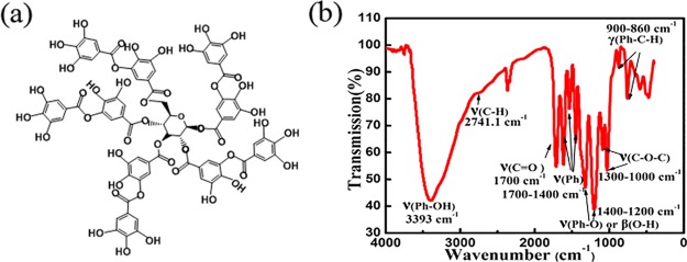
Figure 1a shows the molecular structure of TA. It is found that TA contains a large variety of oxygen-containing functionalities including polyphenol, quinone, and ketone groups, which can be confirmed from the Fourier transform infrared (FTIR) spectrum, as shown in Figure 1b. In detail, the strong peak at 3393 cm–1 can be attributed to the existence of a polyphenolic hydroxyl moiety (Ph–OH). The weak shoulder at 2741.1 cm–1 is ascribed to the stretching of a C–H group. The peaks near the 1700 cm–1 region might have originated from carbonyl stretching (C=O). The peaks at 1700–1400 cm–1 can be assigned to the vibrations of the benzene ring. The peaks at 1400–1200 cm–1 can be indexed to the O–H deformation of the carboxyl group (O=C–O–H). The peaks ranging from 1300 to 1000 cm–1 are due to the stretching of carbohydrate or alcoholic bonds (C–O–C or C–O). The wavenumbers from 900 to 860 cm–1 might have resulted from the plane vibrations of aromatic C–H, benzene, and alkyl benzene bonds. This structural information implies the existence of redox functionalities and the resulting potential for ion accumulation.
Figure 1.
(a) Typical structure model of TA. (b) FTIR spectrum of TA.
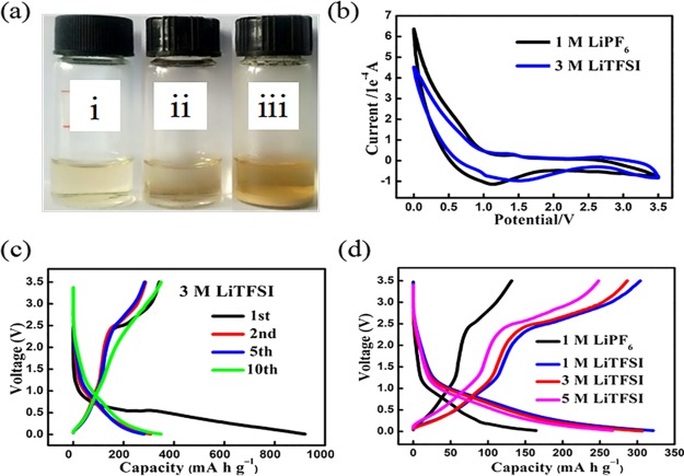
To probe the dissolution behavior of TA in various electrolytes, photographic observations were conducted (shown in the Experimental Section). As shown in Figure 2a, TA can be easily dissolved into the mixture solvent (ethylene carbonate/diethylcarbonate [EC/DEC]) to form a clear solution (bottle i). If the same amount of TA is added to 1 M LiPF6, most of the TA gets dissolved, forming a turbid solution (bottle ii). Most interestingly, a large amount of TA is precipitated at the bottom of the vessel because of the addition of LiTFSI (bottle iii). This discrepancy in the dissolving capacity suggests that the addition of LiTFSI can effectively suppress the dissolution of TA into nonpolar electrolytes (EC/DEC).
Figure 2.
(a) Photograph of dissolution of TA in (i) ethylene carbonate/diethylcarbonate (EC/DEC) solvent, (ii) 1 M LiPF6, and (iii) 1 M LiTFSI; (b) cyclic voltammograms of TA in 1 M LiPF6 and 3 M LiTFSI in the potential range from 0 to 3.5 V (vs Li+/Li) at a scan rate of 1 mV s–1; (c) charge–discharge profiles of TA in 3 M LiTFSI at a current density of 10 mA g–1; and (d) second charge–discharge profiles of TA in different electrolytes at a current density of 10 mA g–1.
To evaluate the electrochemical performance of TA in different electrolytes, cyclic voltammograms (CVs) were performed with a half cell system, where TA was used as the active material and lithium foil worked as both the reference electrode and the counter electrode, respectively (Figures 2b and S2). As demonstrated in Figure 2b, reduction peaks centered at 1.1 and 1.5 V are observed for TA in 1 M LiPF6 and 3 M LiTFSI, respectively, during the cathodic scan from 3.5 to 0 V. Similar reaction peaks are also observed in 1 M LiTFSI and 5 M LiTFSI. Accompanying by the inconspicuous oxidation peaks during the anodic scans, the reduction peaks imply the potential application of TA as the anode material for lithium ion accumulation.33 The current increase below 1 V was attributed to the insertion/extraction of solvated lithium ions into/from the electrode, accompanied by a sharp current increase. In addition, the galvanostatic charge–discharge profiles were also examined (Figures 2c,d and S3). As shown in Figure 2c, TA experiences a sharp voltage drop to 1.0 V and follows a gentle slope from 1.0 to 0.1 V with a specific discharge capacity of 900 mA h g–1 in 3 M LiTFSI during the first discharge. After the intercalation of lithium ions, TA releases a capacity of 312 mA h g–1 with an initial Coulombic efficiency (CE) of 34.6%. Such irreversible capacity loss might be ascribed to electrolyte decomposition, the formation of SEI, and partial dissolution of TA, which are common phenomena for LIB anode materials at the first cycle.34 After that, the lithium ion insertion and extraction processes become relatively reversible, with a capacity of 306.83 mA h g–1 and a CE of 93.4%. Similar tendencies are also found in other electrolytes containing LiTFSI (Figure S3). On the contrary, TA presents poorly discharged SCs of 376.67 and 164.16 mA h g–1 for the first and second cycles in 1 M LiPF6. Combined with the summarized charge–discharge behavior during the second cycling test (Figure 2d), the discrepancies in lithium ion storage solidify that LiTFSI works more efficiently to inhibit the dissolution of TA than LiPF6 does. To further illuminate the differences in morphology after lithiation, scanning electron microscopy (SEM) was performed (Figure S1). It can be clearly seen that after lithiation the original granular TA particle with a size of 300–600 nm accumulated and boundaries faded away because of its dissolution and lithiation in electrolyte. After 30 cycles, a solid polymer film was formed.
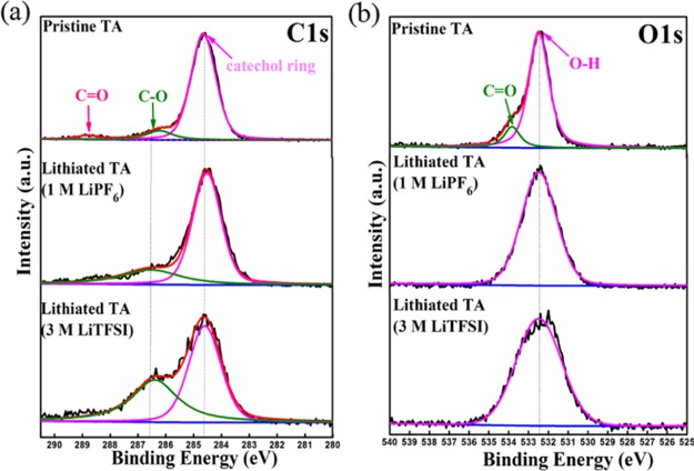
To further understand the lithium ion storage mechanism, FTIR spectra of lithiated TA in different electrolytes were recorded. As elucidated in Figure 3, after the discharging process, the peaks located at 1700 and 1300 cm–1, assigned to C=O stretching and C–O–C symmetric stretching in the pristine TA framework, disappeared, implying the successful insertion of lithium ions. In addition, the intensity of the in-plane bend of C–O–H of the hydroxyl group at 1506 cm–1 strengthened, accompanied by the intercalation of lithium ions. A band at 1341 cm–1 indexed to the stretch of C–O was shown at lithiated TA in 1 M LiTFSI and 5 M LiTFSI, but it strengthened at lithiated TA in 3 M LiTFSI, implying a more complete reduction and the intercalation of more lithium ions of TA in 3 M LiTFSI than in 1 M LiTFSI and 5 M LiTFSI. Furthermore, ex situ X-ray photoelectron spectroscopy (XPS) spectra were also recorded and analyzed. As shown in Figure 4, some differences are observed in the collected C1s and O1s spectra between the pristine and lithiated electrodes. The peaks at 284.7 eV correspond to the catechol ring. The peak located at 288.6 eV (C=O) in the pristine TA framework disappeared after the intercalation of lithium ions, thus indicating the consumption of carbonyl groups. The peak located at 286.5 eV assigned to C–O increased in strength at the same time. The above analysis proved that the transformation from ester carbonyl groups to C–O was finished during the initial stage of the first lithiation process. C–O in lithiated TA in 3 M LiTFSI is strengthened more than that in 1 M LiPF6, accounting for the more complete reduction and the intercalation of more lithium ions with TA in 3 M LiTFSI. As for the O1s spectrum (Figure 4b), the peak corresponding to C=O centered at 533.9 eV also disappeared in the lithiated state, which was consistent with the C1s spectra.
Figure 3.
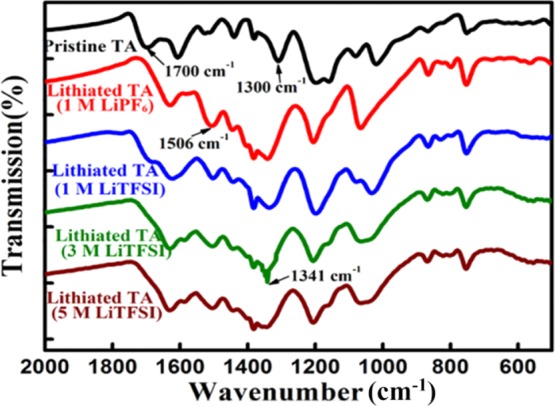
FTIR spectra of pristine TA and lithiated TA in different electrolytes (1 M LiPF6, 1 M LiTFSI, 3 M LiTFSI, and 5 M LiTFSI).
Figure 4.
XPS spectra of (a) C1s and (b) O1s of pristine TA electrodes and lithiated TA electrodes recovered from the dismantled cells.
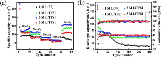
Furthermore, the rate capability and the cycling stability of TA in different electrolytes were also investigated (Figure 5a,b). Two important correlations were observed: (1) LiTFSI has a positive effect on enhancing the capacity and improving the cycling stability. In detail, the SCs of TA in other electrolytes containing LiTFSI are always higher than that in LiPF6 at the same current density (Figure 5a). However, over 250 cycles, the retained SC in LiTFSI systems (approximately 100 mA h g–1) is also higher than that in LiPF6 (26.5 mA h g–1) (Figure 5b). (2) The optimization of the concentration of LiTFSI can affect the Li-ion storage behavior of TA. For example, TA delivers much higher SCs and rate capabilities in 3 M LiTFSI than in 1 M LiTFSI and 5 M LiTFSI (Figure 5a). The SCs in 3 M LiTFSI fluctuate with the variation in current density: 306.33 mA h g–1 (10 mA g–1), 245.17 mA h g–1 (20 mA g–1), and 133.67 mA h g–1 (40 mA g–1). Furthermore, a comparatively high capacity retention is also observed for TA in 3 M LiTFSI. Hence, it is deduced that the charge transfer behavior of organic materials can be controlled by changing the counterions or the concentration of salts in the electrolyte.
Figure 5.
(a) Rate capabilities of TA at current densities from 10 to 80 mA g–1 in different electrolytes and (b) cycling performance of TA at a constant current of 40 mA g–1 in different electrolytes.
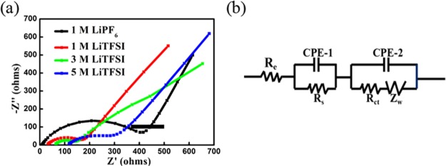
To further elucidate the electrochemical kinetics, electrochemical impedance spectroscopy (EIS) was recorded. Figure 6a shows the Nyquist plots of TA in different electrolytes. Besides the intercepts on the Z′ axis, which represent the internal resistance (Re, e.g., electrolyte resistance, contact resistances between particles and/or between the electrode and the current collector), two semicircles and an inclined line are found on the impedance curves. According to the equivalent circuit model (Figure 6b), the semicircle at high frequencies can be assigned to the resistance (Rs) and constant phase element (CPE-1) of the SEI film. The semicircle at medium frequencies can be ascribed to the charge transfer resistance (Rct) and a nonideal constant phase element (CPE-2) of the electrode/electrolyte interface. The inclined line in the low-frequency region can be considered the Warburg impedance (Zw) caused by the diffusion of Li ions in the electrode materials.35,36 After fitting, the obtained parameters are summarized in Table S1. It has been observed that electrolytes containing LiTFSI have faster electrochemical kinetics than those containing LiPF6. Most impressively, TA presents the smallest Rs and Rct values (1.507 × 10³ and 82.47 Ω) in 3 M LiTFSI compared to those in the other electrolytes, implying an excellent electrochemical performance of TA in 3 M LiTFSI solution.
Figure 6.
(a) Electrochemical impedance spectra of TA in different electrolytes (1 M LiPF6, 1 M LiTFSI, 3 M LiTFSI, and 5 M LiTFSI). (b) Equivalent circuit model for electrochemical impedance spectroscopy (EIS).
3. Conclusions
Through the integration of chemical analyses with electrochemical characterizations, TA has been validated as a promising anode material for LIBs, benefiting from the abundant existence of oxygen-containing functionalities and the correlated redox reactions. Most impressively, using LiTFSI instead of LiPF6 can both improve the electrochemical kinetics of TA and inhibit the dissolution of TA in organic media, resulting in a significant enhancement in energy storage (high specific capacity, excellent rate capability, and a stable long cycling life). It is envisioned that this work will not only push forward the exploration of organic electrode materials from natural resources but also pioneer research on electrolytes to solve the dissolution issues in organic energy storage devices.
4. Experimental Section
4.1. Preparations of Electrolytes
EC and DEC with a volume ratio of 4:6 were mixed together to form the solvent. Then, different amounts of salt [lithium bis(trifluoromethanesulfonyl)imide (LiN(SO2CF3)2, LiTFSI) or lithium hexafluorophosphate (LiPF6)] were dissolved in the mixture to form electrolytes with different concentrations (1 M LiTFSI, 3 M LiTFSI, 5 M LiTFSI, and 1 M LiPF6).
4.2. Assembly of Batteries
For the preparation of working electrodes, a certain amount of TA (Sigma-Aldrich), conducting carbon (Super P carbon black from Alfa Aesar), and binder (polytetrafluoroethylene, PTFE) were mixed with a mass ratio of 6.5:3:0.5 using a pestle and mortar followed by pressing on a current collector (copper foil). After drying in vacuum, the as-prepared working electrodes, pure Li metal, and Celgard membrane (3501) were used as the cathode, anode, and separator, respectively, to fabricate coin-type (2032) batteries with different electrolytes (1 M LiTFSI, 3 M LiTFSI, 5 M LiTFSI, and 1 M LiPF6).
4.3. Characterization and Electrochemical Tests
To illustrate the differences in dissolution, the same amount of TA (30 mg) was added to EC/DEC, 1 M LiPF6, and 1 M LiTFSI in the same volume (3 mL), which were labeled as i, ii, and iii, respectively. The FTIR spectrum was measured on a Shimadzu IR Prestige-21 FTIR spectrophotometer. The CV curves were recorded using a CHI630D electrochemical analyzer. The discharge and charge measurements were taken using a Neware battery test system. The morphologies of the electrode before and after lithiation were characterized using an environmental SEM (FEI, QuanTA-200F). The elemental compositions of the products were characterized using XPS (Thermo-VG; ESCALAB 250) with an Al Kα (1486.6 eV) X-ray source. EIS measurements were taken using a Princeton PARSTAT 2273 electrochemical workstation over a frequency range of 100 mHz to 100 kHz with an amplitude of 10 mV. For the calculation of all gravimetric capacities/currents, only the mass of the active material was taken into account. The gravimetric capacitance of a single electrode was calculated according to the following equation
where Cg (mA h g–1) is the gravimetric specific capacitance, I (mA) is the charge/discharge current, t (s) is the charge/discharge time, and Δm (mg) is the mass loading of active materials.
Acknowledgments
This project was supported by the Natural Science Foundation of China (51663016, 21403295, and U1303191), the National Key Technology Research and Development Program of the Ministry of Science and Technology of China (2015BAD14B06), and the Natural Science Foundation of Jiangxi Province (2016BAB203075 and 20162BCB23015).
Supporting Information Available
The Supporting Information is available free of charge on the ACS Publications website at DOI: 10.1021/acsomega.6b00504.
SEM images, electrochemical tests, and the fitted values for EIS analysis (PDF)
The authors declare no competing financial interest.
Supplementary Material
References
- Armand M.; Tarascon J.-M. Building better batteries. Nature 2008, 451, 652–657. 10.1038/451652a. [DOI] [PubMed] [Google Scholar]
- Liu H.; Li W.; Shen D.; Zhao D.; Wang G. Graphitic carbon conformal coating of mesoporous TiO2 hollow spheres for high-performance lithium ion battery anodes. J. Am. Chem. Soc. 2015, 137, 13161–13166. 10.1021/jacs.5b08743. [DOI] [PubMed] [Google Scholar]
- Reddy M. V.; Rao G. V. S.; Chowdari B. V. R. Metal oxides and oxysalts as anode materials for Li ion batteries. Chem. Rev. 2013, 113, 5364–5457. 10.1021/cr3001884. [DOI] [PubMed] [Google Scholar]
- Lee S.-Y.; Choi K.-H.; Choi W.-S.; Kwon Y. H.; Jung H.-R.; Shin H.-C.; Kim J. Y. Progress in flexible energy storage and conversion systems, with a focus on cable-type lithium-ion batteries. Energy Environ. Sci. 2013, 6, 2414–2423. 10.1039/c3ee24260a. [DOI] [Google Scholar]
- Wang Y.; Liu B.; Li Q.; Cartmell S.; Ferrara S.; Deng Z. D.; Xiao J. Lithium and lithium ion batteries for applications in microelectronic devices: A review. J. Power Sources 2015, 286, 330–345. 10.1016/j.jpowsour.2015.03.164. [DOI] [Google Scholar]
- Etacheri V.; Marom R.; Elazari R.; Salitra G.; Aurbach D. Challenges in the development of advanced Li-ion batteries: A review. Energy Environ. Sci. 2011, 4, 3243–3262. 10.1039/c1ee01598b. [DOI] [Google Scholar]
- Whittingham M. S. Ultimate limits to intercalation reactions for lithium batteries. Chem. Rev. 2014, 114, 11414–11443. 10.1021/cr5003003. [DOI] [PubMed] [Google Scholar]
- Obrovac M. N.; Chevrier V. L. Alloy negative electrodes for Li-ion batteries. Chem. Rev. 2014, 114, 11444–11502. 10.1021/cr500207g. [DOI] [PubMed] [Google Scholar]
- Deng S.-R.; Kong L.-B.; Hu G.-Q.; Wu T.; Li D.; Zhou Y.-H.; Li Z.-Y. Benzene-based polyorganodisulfide cathode materials for secondary lithium batteries. Electrochim. Acta 2006, 51, 2589–2593. 10.1016/j.electacta.2005.07.045. [DOI] [Google Scholar]
- Janoschka T.; Hager M. D.; Schubert U. S. Powering up the future: Radical polymers for battery applications. Adv. Mater. 2012, 24, 6397–6409. 10.1002/adma.201203119. [DOI] [PubMed] [Google Scholar]
- Jähnert T.; Hager M. D.; Schubert U. S. Application of phenolic radicals for antioxidants, as active materials in batteries, magnetic materials and ligands for metal-complexes. J. Mater. Chem. A 2014, 2, 15234–15251. 10.1039/c4ta03023k. [DOI] [Google Scholar]
- Wang S.; Wang L.; Zhu Z.; Hu Z.; Zhao Q.; Chen J. All organic sodium-ion batteries with Na4C8H2O6. Angew. Chem., Int. Ed. 2014, 53, 5892–5896. 10.1002/anie.201400032. [DOI] [PubMed] [Google Scholar]
- Lee M.; Hong J.; Kim H.; Lim H.-D.; Cho S. B.; Kang K.; Park C. B. Organic nanohybrids for fast and sustainable energy storage. Adv. Mater. 2014, 26, 2558–2565. 10.1002/adma.201305005. [DOI] [PubMed] [Google Scholar]
- Zhong H.; Wang G.; Song Z.; Li X.; Tang H.; Zhou Y.; Zhan H. Organometallic polymer material for energy storage. Chem. Commun. 2014, 50, 6768–6770. 10.1039/c4cc01572j. [DOI] [PubMed] [Google Scholar]
- Chen H.; Armand M.; Courty M.; Jiang M.; Grey C. P.; Dolhem F.; Tarascon J.-M.; Poizot P. Lithium salt of tetrahydroxybenzoquinone: Toward the development of a sustainable Li-ion battery. J. Am. Chem. Soc. 2009, 131, 8984–8988. 10.1021/ja9024897. [DOI] [PubMed] [Google Scholar]
- Song Z.; Zhou H. Towards sustainable and versatile energy storage devices: An overview of organic electrode materials. Energy Environ. Sci. 2013, 6, 2280–2301. 10.1039/c3ee40709h. [DOI] [Google Scholar]
- Hu P.; Wang H.; Yang Y.; Yang J.; Lin J.; Guo L. Renewable-biomolecule-based full lithium-ion batteries. Adv. Mater. 2016, 28, 3486–3492. 10.1002/adma.201505917. [DOI] [PubMed] [Google Scholar]
- Zhu H.; Yin J.; Zhao X.; Wang C.; Yang X. Humic acid as promising organic anodes for lithium/sodium ion batteries. Chem. Commun. 2015, 51, 14708–14711. 10.1039/c5cc04772b. [DOI] [PubMed] [Google Scholar]
- Yao M.; Yamazaki S.-I.; Senoh H.; Sakai T.; Kiyobayashi T. Crystalline polycyclic quinone derivatives as organic positive-electrode materials for use in rechargeable lithium batteries. Mater. Sci. Eng., B 2012, 177, 483–487. 10.1016/j.mseb.2012.02.007. [DOI] [Google Scholar]
- Liang Y.; Zhang P.; Yang S.; Tao Z.; Chen J. Fused heteroaromatic organic compounds for high-power electrodes of rechargeable lithium batteries. Adv. Energy Mater. 2013, 3, 600–605. 10.1002/aenm.201200947. [DOI] [Google Scholar]
- Liang Y.; Zhang P.; Chen J. Function-oriented design of conjugated carbonyl compound electrodes for high energy lithium batteries. Chem. Sci. 2013, 4, 1330–1337. 10.1039/c3sc22093a. [DOI] [Google Scholar]
- Hanyu Y.; Honma I. Rechargeable quasi-solid state lithium battery with organic crystalline cathode. Sci. Rep. 2012, 2, 453. 10.1038/srep00453. [DOI] [PMC free article] [PubMed] [Google Scholar]
- Kwon M.-S.; Choi A.; Park Y.; Cheon J. Y.; Kang H.; Jo Y. N.; Kim Y.-J.; Hong S. Y.; Joo S. H.; Yang C.; Lee K. T. Synthesis of ordered mesoporous phenanthrenequinone-carbon via π–π interaction-dependent vapor pressure for rechargeable batteries. Sci. Rep. 2014, 4, 7404. 10.1038/srep07404. [DOI] [PMC free article] [PubMed] [Google Scholar]
- Song Z.; Zhan H.; Zhou Y. Anthraquinone based polymer as high performance cathode material for rechargeable lithium batteries. Chem. Commun. 2009, 4, 448–450. 10.1039/b814515f. [DOI] [PubMed] [Google Scholar]
- Kalhoff J.; Bresser D.; Bolloli M.; Alloin F.; Sanchez J.-Y.; Passerini S. Enabling LiTFSI-based electrolytes for safer lithium-ion batteries by using linear fluorinated carbonates as (Co) solvent. ChemSusChem 2014, 7, 2939–2946. 10.1002/cssc.201402502. [DOI] [PubMed] [Google Scholar]
- Lewandowski A.; Świderska-Mocek A. Ionic liquids as electrolytes for Li-ion batteries—An overview of electrochemical studies. J. Power Sources 2009, 194, 601–609. 10.1016/j.jpowsour.2009.06.089. [DOI] [Google Scholar]
- Lahiri A.; Borisenko N.; Borodin A.; Olschewski M.; Endres F. Characterisation of the solid electrolyte interface during lithiation/delithiation of germanium in an ionic liquid. Phys. Chem. Chem. Phys. 2016, 18, 5630–5637. 10.1039/c5cp06184a. [DOI] [PubMed] [Google Scholar]
- Suo L.; Hu Y.-S.; Li H.; Armand M.; Chen L. A new class of solvent-in-salt electrolyte for high-energy rechargeable metallic lithium batteries. Nat. Commun. 2013, 4, 1481. 10.1038/ncomms2513. [DOI] [PubMed] [Google Scholar]
- Shin E. S.; Kim K.; Oh S. H.; Cho W. I. Polysulfide dissolution control: The common ion effect. Chem. Commun. 2013, 49, 2004–2006. 10.1039/c2cc36986a. [DOI] [PubMed] [Google Scholar]
- Zhang Y. Z.; Liu S.; Li G. C.; Li G. R.; Gao X. P. Sulfur/polyacrylonitrile/carbon multi-composites as cathode materials for lithium/sulfur battery in the concentrated electrolyte. J. Mater. Chem. A 2014, 2, 4652–4659. 10.1039/c3ta14914e. [DOI] [Google Scholar]
- Özacar M.; Soykan C.; Şengil İ. A. Studies on synthesis, characterization, and metal adsorption of mimosa and valonia tannin resins. J. Appl. Polym. Sci. 2006, 102, 786–797. 10.1002/app.23944. [DOI] [Google Scholar]
- Özacar M.; Şengil İ. A.; Türkmenler H. Equilibrium and kinetic data, and adsorption mechanism for adsorption of lead onto valonia tannin resin. Chem. Eng. J. 2008, 143, 32–42. 10.1016/j.cej.2007.12.005. [DOI] [Google Scholar]
- Lan T.; Qiu H.; Xie F.; Yang J.; Wei M. Rutile TiO2 mesocrystals/reduced graphene oxide with high-rate and long-term performance for lithium-ion batteries. Sci. Rep. 2015, 5, 8498. 10.1038/srep08498. [DOI] [PMC free article] [PubMed] [Google Scholar]
- Wang H.-G.; Yuan S.; Si Z.; Zhang X.-B. Multi-ring aromatic carbonyl compounds enabling high capacity and stable performance of sodium-organic batteries. Energy Environ. Sci. 2015, 8, 3160–3165. 10.1039/c5ee02589c. [DOI] [Google Scholar]
- Xu J.; Jeon I.-Y.; Seo J.-M.; Dou S.; Dai L.; Baek J.-B. Edge-selectively halogenated graphene nanoplatelets (XGnPs, X = Cl, Br, or I) prepared by ball-milling and used as anode materials for lithium-ion batteries. Adv. Mater. 2014, 26, 7317–7323. 10.1002/adma.201402987. [DOI] [PubMed] [Google Scholar]
- Hu L.; Ren Y.; Yang H.; Xu Q. Fabrication of 3D hierarchical MoS2/polyaniline and MoS2/C architectures for lithium-ion battery applications. ACS Appl. Mater. Interfaces 2014, 6, 14644–14652. 10.1021/am503995s. [DOI] [PubMed] [Google Scholar]
Associated Data
This section collects any data citations, data availability statements, or supplementary materials included in this article.


