Abstract
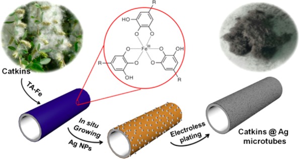
Catkin, a natural hollow fiber, is used as a template to fabricate light, flexible, and electrically conductive silver microtubes with a high aspect ratio. The template is functionalized with tannic acid (TA)–Fe coordination complexes. Because of the metal ion chelating ability and reducibility of TA, silver nanoparticles (Ag NPs) can be formed in situ on the fiber’s surface. The as-formed Ag NPs can act as nucleation sites in subsequent electroless silver plating, leading to the formation of a compact and uniform silver coating on the microtube. The coating is constructed by densely packed Ag NPs of only 15 ± 5 nm in diameter. Because of the tight accumulation and small size of the Ag NPs, the resulting silver-coated microtubes, without any post-treatment, show an electrical resistivity of 1500 mΩ·cm at a bulk density of 0.6 g·cm–3. We find that the in situ formed nucleation sites and the stirring speed in the electroless plating play important roles in the formation of a silver coating with a high electrical conductivity. This method may be extended to fabricate conductive nanocoatings on other substrates.
1. Introduction
Owing to their ideal conductivity and ability to adopt different shapes,1 flexible conductive materials have found applications in stretchable displays,2,3 sensors,4−6 electromagnetic shielding,7,8 antistatic,9,10 and so on. Generally, flexible conductive materials are made by coating metallic layers on flexible substrates, such as polymer fibers,11,12 rubbers,13 and even biomaterials.4,14 Because of its ease of reduction,15 moderate cost, and high electrical conductivity, silver is an ideal candidate for use as a metal coating material. A variety of methods have been reported for the synthesis of silver coatings on different substrates. Among these methods, electroless plating11,12,16−18 is one of the most effective because of its relatively low cost, simple equipment, and ability to fabricate uniform coatings. Nevertheless, the large size of the resultant nanoparticles (NPs) and the organic stabilizers capped on the particle surface after electroless plating lead to high junction resistance. To achieve high conductivity, post-treatments like thermal sintering,7 electrical sintering,19 and microwave radiation20,21 are necessary.
Previously, we reported the fabrication of conductive Ag NPs films on various polydopamine-modified substrates and developed a simple method to rapidly sinter Ag NPs in an electrolyte solution at room temperature.16 However, the strategy has disadvantages, e.g., the surface modification process is time-consuming and dopamine is expensive. Tannic acid (TA) is a natural polyphenol containing a central glucose core that is completely esterified with gallic acid dimers (its molecular structure is shown in Figure S1). The abundant phenolic hydroxyl groups endow TA with antioxidative and metal ion chelating abilities. TA can also be used as a green reducing agent for fabricating noble metal NPs because of its reducibility.22−24 Recently, Caruso et al. reported a rapid and low-cost strategy for the preparation of robust coatings on various substrates through the one-step assembly of TA–Fe coordination complexes.25−27 Similar to polydopamine chemistry, the strategy of using TA–Fe coordination complexes has been applied to various surface modification processes.28,29
Willows (scientific name: Salix babylonica Linn.) are well-known woody plants widely distributed throughout the northern hemisphere. They bear compact unisexual inflorescences called catkins. Willow catkins possess unique characteristics, such as having good flexibility and being fluffy and light. The main chemical composition of the willow catkin is cellulose.37 Similar to other biological fibers, the surface of catkin is hydrophobic because of the existence of a vegetable wax layer. Removing the wax layer from the catkin surface can expose hydroxyl groups and improve the catkin’s hydrophilicity. The surface hydroxyl groups can form intermolecular hydrogen bonds with TA, which is advantageous for anchoring TA–Fe coordination complexes on the surface.38 Herein, we demonstrate the preparation of light, flexible, and electrically conductive microtubes using hollow catkin fibers as the template. The catkin surface was modified by TA–Fe coordination complexes, and Ag NPs were formed in situ on the surface as the nucleation sites for subsequent electroless plating. We found that the nucleation sites and a high stirring speed during electroless plating play important roles for the formation of a dense silver coating constructed of small Ag NPs on the surface of the fiber. The resultant microtubes show good conductivity even without post-treatment. The procedure is simple and low-cost and may be applied to various substrates for the formation of conductive silver coatings.
2. Results and Discussion
2.1. Morphology and Structure
The fabrication process is schematically shown in Figure 1. The natural catkin fiber was first modified by TA–Fe coordination complexes. The color of the fibers changed from bright white to light blue. Because of the metal ion chelating ability and reducibility of TA, the as-formed Catkins@TA–Fe could bind Ag+ on the fiber’s surface in AgNO3 solution; then, the Ag+ is reduced to form Ag NPs on the fiber. Because of the formation of the Ag NPs, the fibers were pale brown. The in situ formed Ag NPs, which we termed the seed layer, act as nucleation sites in subsequent electroless plating. Finally, a compact Ag NP coating was formed on the fiber surface, and silvery gray colored microtubes with obvious metallic luster were obtained.
Figure 1.
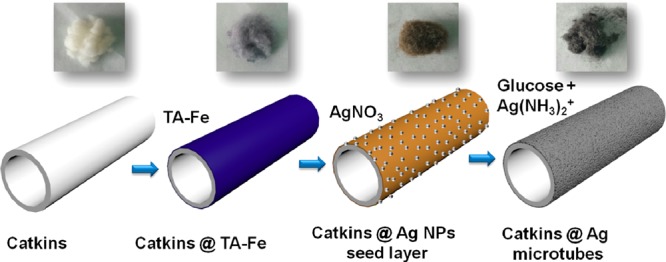
Schematic illustration of the synthesis of silver microtubes using catkin fibers as the template. Photos show the color change of the fibers during the preparation.
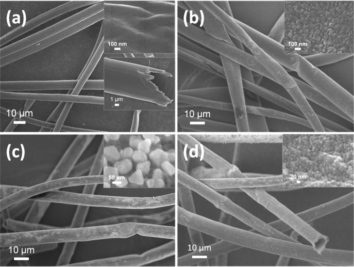
Figure 2 shows the change in morphology of the fibers during the modification. The pristine catkin exhibits a microtubular structure with a diameter of 6–10 μm, a wall thickness of 0.5–1 μm, and a smooth external surface (Figure 2a). After it is modified by TA–Fe, the outer surface of the fiber becomes rough due to the formation of TA–Fe coordination complexes (Figure 2b). The in situ formed Ag NPs on the Catkins@Ag NP seed layer have an average diameter of about 70 nm (Figure 2c). As shown in Figure S2, the morphology of the Catkins@Ag NP seed is affected by the reaction time. The quantity and particle size of the Ag NPs increased with the reaction time. To ensure the formation of a uniform silver coating in the subsequent step, the optimal time for the growth of Ag NPs is 12 h. Figure 2d shows that a compact silver coating is formed on the fiber surface after electroless plating. The silver coating is relatively smooth and is composed of tiny Ag NPs densely packed to cover the fiber surface completely. The diameter of the small Ag NPs on the final Catkins@Ag microtubes is only 15 ± 5 nm. The morphology variation combined with the color changes of the fibers suggested that a compact and uniform silver coating was formed on the catkin surface.
Figure 2.
SEM images of (a) original catkins, (b) Catkins@TA–Fe, (c) Catkins@Ag NP seed layer, and (d) Catkins@Ag microtubes. Insets are magnified images.
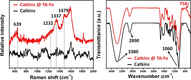
The change in composition was confirmed by Raman (Figure 3a) and FT-IR (Figure 3b) spectra, further indicating the successful surface modification of the fiber by TA–Fe. In the Raman spectra, new characteristic peaks of Catkins@TA–Fe at 1232, 1337, and 1479 cm–1 correspond to catechol ring vibrations, indicating the presence of TA. The peak at 639 cm–1 is due to the bidentate chelation of Fe3+ by the phenolic oxygen of catechol, which has been used as an indicator of the presence of TA–Fe coordination.30 In the FT-IR spectra, the peaks at 3380, 2890, and 1060 cm–1 correspond to OH, CH2 groups, and the C–O–C bond from the glucosidic units, respectively, and they are characteristic peaks of cellulose.39 The new peak of Catkins@TA–Fe at 758 cm–1 corresponds to multisubstituted aromatic rings in TA.31
Figure 3.
(a) Raman and (b) FT-IR spectra of catkins and Catkins@TA–Fe.
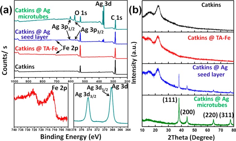
XPS results are displayed in Figure 4a. For both Catkins@TA–Fe and Catkins@Ag NP seed layer, the Fe 2p signal is detected. The high-resolution Fe 2p spectrum of Catkins@TA–Fe shows a main peak at a binding energy of about 711 eV with a 2p peak separation of about 14–16 eV, confirming the presence of Fe3+ species and the formation of TA–Fe coordination complexes on the fiber surface.27 The strong signals of Ag at 368 eV are detected for both the Catkins@Ag NP seed layer and Catkins@Ag microtubes. In the high-resolution of Ag 3d spectrum of Catkins@Ag microtubes, peaks at 368 and 374 eV correspond to Ag 3d5/2 and Ag 3d3/2, respectively, confirming the presence of Ag in a metallic state.11
Figure 4.
(a) XPS spectra and (b) XRD patterns of the various fibers.
XRD (Figure 4b) was used to further investigate the crystalline structure. The original catkins have diffraction peaks at approximately 15.0°, 17.0°, and 22.5°, corresponding to the typical (11̅0), (110), and (200) crystal planes of cellulose I.32 These peaks still appears in Catkins@TA–Fe and Catkins@Ag NP seed layer. Along with the formation of the Ag NPs, new peaks appear at 38.1°, 44.3°, 64.4°, and 77.4°, assigned to the (111), (200), (220), and (311) crystal faces of face-centered cubic (fcc) Ag (JCPDS no. 04-0783).29 The XRD peaks of silver in Catkins@Ag microtubes are more intense, whereas the diffraction peaks of cellulose I almost disappeared, implying that the fiber surface was totally coated with a compact silver coating.
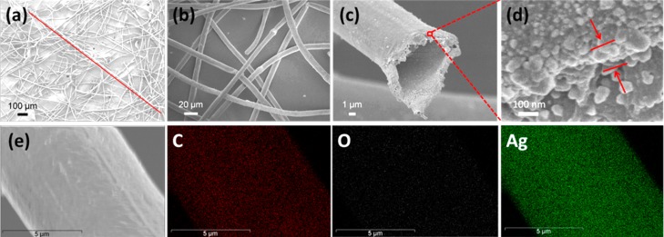
The obtained Catkins@Ag microtubes remain fluffy and exhibit a smooth surface and hollow structure with a high aspect ratio (photo in Figure 1 and SEM images in Figure 5). Typically, a microtube is about 1.7 mm in length, as shown in Figure 5a. The aspect ratio is more than 170. From Figure 5c, it can be seen that Ag NPs are also formed on the inner surface of the hollow fibers. According to thermogravimetric analysis, the amount of Ag loading is determined to be 77 wt % from the differences in weight loss (Figure S3). The thickness of the silver coating is about 130 nm (Figure 5d). The composition of Catkins@Ag microtubes was also surveyed by EDS. As shown in Figure 5e, C, O, and Ag are detected, and the intense and uniform green color illustrates that abundant Ag is well-distributed on the fiber surface. We also conducted UV–vis analysis of Ag NPs from the various fibers in solution. As shown in Figure S5, the plasmon band of Ag NPs at 429 nm suggested the formation of a Ag NP seed layer. The blue shift in the absorption peak to 407 nm after electroless silver plating is consistent with the decrease in size of newly formed Ag NPs.40 In addition, the increase in the peak width of the blue-shifted absorption peak might be ascribed to the superposition of two peaks (429 and 407 nm), indicating the existence of both large Ag seeds and small electroless plating-produced Ag NPs in the final nanocoatings.
Figure 5.
SEM images of the resultant Catkins@Ag microtubes showing their (a) high aspect ratio, (b) smooth surface, and (c) hollow structure. The line in (a) indicates a continuous microtube in the image. (d) Cross-sectional SEM images of Catkins@Ag microtubes. (e) Elemental mapping images of Catkins@Ag microtubes.
2.2. Electrically Conductive Properties
From the above-mentioned results, a uniform silver coating composed of densely packed small Ag NPs was formed on the fiber surface. The high aspect ratio of the microtube is benificial for constructing conductive networks, and the densely packed small Ag NPs also help to reduce the junction resistance between the nanoparticles. Interestingly, the electric conductivity of the silver microtubes is good enough for them to be applied as flexible and lightweight conductive materials without any post-treatment.
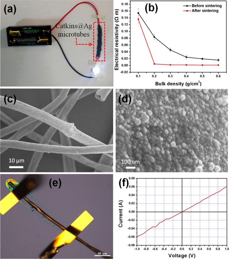
As shown in Figure 6a, the obtained Catkins@Ag microtubes can act as a part of an electrical circuit to light an LED when the required voltage is supplied. Because of the fluffy nature of the prepared microtubes, the electrical resistivity of the microtubes depends on the bulk density of the samples, as shown in Figure 6b. The increase in the bulk density of Catkins@Ag microtubes leads to an obvious decrease in the electrical resistivity. The electrical resistivity does not decrease noticeably with a further increase in the bulk density. This is because an increase in the bulk density will result in more contact among the fibers; thus, more conductive paths will be constructed. When the microtubes are compressed to a certain degree, a nearly complete conductive network will be formed. Further compression of the microtubes has no obvious effect on the conductive path.
Figure 6.
(a) Photo of the Catkins@Ag microtubes used directly as a conductor for an electrical circuit to power an LED. (b) Effects of bulk density and sintering on the electrical resistivity of the Catkins@Ag microtubes. (c, d) SEM images of Catkins@Ag microtubes after sintering. (e) Optical microscope photograph and (f) corresponding I–V curve of a single Catkins@Ag microtube.
Generally, post-treatments are necessary to achieve high conductivity after electroless plating.7,16 A dramatic decrease in the electrical resistivity of the Ag coating will result since the post-treatment helps to remove the organic stabilizer capped on the Ag NPs and make the Ag NPs fuse to form a dense coating. For example, a 4 orders of magnitude increase in the electrical conductivity has been realized after sintering the Ag NP coating.16 Herein, the electrical resistivity is 1.5 × 10³ mΩ·cm at a bulk density of 0.6 g·cm–3. After being sintered at 200 °C for 2 h, the morphology of the silver coating does not show an obvious change (Figure 6c,d), and the electrical resistivity decreases to 1.1 × 10² mΩ·cm at a bulk density of 0.6 g·cm–3, showing only a 1 order of magnitude change. The results indicate that the post-treatment has a less dramatic effect on increasing the electrical conductivity compared with that in previous studies.7,16 We also studied the electrical conductivity of a single Catkins@Ag microtube. As shown in Figure 6e, the two ends of a single Catkins@Ag microtube were connected using a micromanipulator 6150 probe station. The corresponding I–V curve (Figure 6f) shows that the single microtube has excellent electrical conductivity. The calculated electrical resistivity is about 0.7 mΩ·cm.
The electrical resistivity of Catkins@Ag microtubes and some other conductive silver-plated materials reported are listed in Table 1. Obviously, the Ag NPs that we prepared have a smaller size than those reported according to the SEM images provided in the literature, even though accurate data were not given. Using the pressing plate method, which is mentioned in previous reports,11,33,34 the measured electrical resistivity of the microtube tablet was as low as 0.33 mΩ·cm, showing a competitive electrical conductivity. There are seveal reasons for the good electrical conductivity of our samples. First, the diameter of the Ag NPs on the microtubes is only approximately 15 ± 5 nm. The smaller the nanoparticles, the larger the specific surface area, which is beneficial for the mutual contact of the Ag NPs. Second, the small Ag NPs are densely packed, resulting in a complete silver coating with fewer defects on the fiber suface. Third, the thickness of the organic stabilizer (in this case, gluconic acid) capped on the particle surface after electroless plating is only 2 nm (Figure S4). Compared with our previous work, in which the capped stabilizer was about 10 nm thick,16 the organic layer is too thin to significantly impair the electrical conductivity of the obtained silver coating.
Table 1. Electrical Resistivity of Catkins@Ag Microtubes Compared to That of Other Silver-Plated Materials.
2.3. Effect Factors on Morphologies and Electrically Conductive Properties
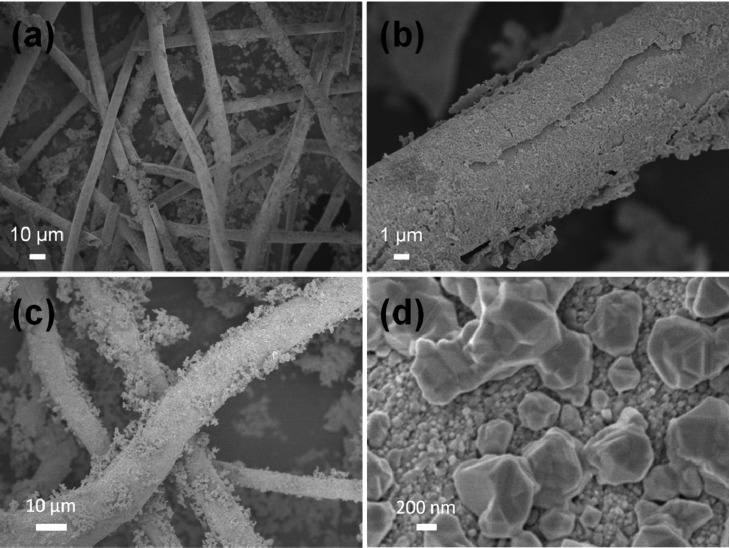
In this study, two factors are important for the formation of a compact and uniform silver coating on the fiber surface. First, the formation of the Ag NP seed layer is indispensable. In the control experiment, Catkins@TA–Fe was directly treated by electroless plating without the formation of the seed layer of Ag NPs. The SEM images (Figure 7a,b) indicate the obtained Ag coating is incompact and nonuniform, and the coating is also discontinuous with a poor adhesion to the fiber. The electrical resistivity of the obtained samples increased to 2.3 × 10⁵ mΩ·cm at a bulk density of 0.6 g·cm–3, much higher than that of 1.5 × 10³ mΩ·cm for the Catkins@Ag microtubes mentioned above. The significant differences in the morphology and conductivity are due to the in situ formed Ag NPs being reduced by TA on the fiber surface; these can act as nucleation sites, which are beneficial to the growth of new Ag NPs in the subsequent electroless plating process. The Ag NP seeds can concentrate Ag+ on the fiber surface, thus facilitating heterogeneous nucleation and growth of the Ag NPs. The Ag NPs formed during electroless plating tend to grow around the seeds and eventually cover the whole surface. Therefore, the seed layer of Ag NPs has an anchoring effect, which helps to form a continuous and closely adhered silver coating.
Figure 7.
(a, b) SEM images of silver-coated catkin fibers directly prepared by electroless plating without Ag NPs seeds. (c, d) SEM images of silver-coated catkin fibers prepared by electroless plating under slow stirring.
Second, the stirring speed was another important factor that might be easily neglected. We found that vigorous stirring (1200 rpm) could prevent the aggregation of Ag NPs and help the Ag NPs to pack densely. In a control experiment where the reaction was performed under slow stirring (200 rpm), the SEM image in Figure 7c shows that lots of silver aggregates deposit on the fiber surface loosely. The high-magnification image (Figure 7d) also exhibits the appearance of large Ag particles on top of the silver coating. The electrical resistivity of the obtained samples was 8.1 × 10⁴ mΩ·cm at a bulk density of 0.6 g·cm–3, 1 order of magnitude larger than that of the Catkins@Ag microtubes. The high stirring speed can improve the diffusion conditions to preserve a relatively stable concentration of Ag(NH3)2+, and the balance between nucleation and growth of Ag NPs can be maintained; this is favorable for the formation of a uniform and dense Ag NP coating.
3. Conclusions
In summary, a uniform and compact silver nanocoating constructed by densely packed Ag NPs with an average diameter of about 15 ± 5 nm was prepared on a TA–Fe modified catkin fiber surface. Reduction of Ag NP seeds by TA before electroless plating and a high stirring speed are important for the formation of a dense silver coating. The resulting silver-coated microtubes remained fluffy and lightweight, have a hollow structure and high aspect ratio, and show good conductivity without any post-treatment. This electroless plating strategy for the fabricatation of a dense silver coating holds remarkable potential in the field of light and flexible conductive materials.
4. Experimental Section
4.1. Materials
Catkins were collected in Beijing, China. TA (ACS grade) and AgNO3 (ACS grade) were purchased from Alfa Aesar. Phosphate buffered saline (PBS) solution (pH 7.4) was obtained from Beijing Dingguo Changsheng Biotechnology Co., Ltd. Glucose (99%) and FeCl3 (97%) were purchased from Sigma-Aldrich. Aqua ammonia (25 wt %) and acetone were obtained from Beijing Chemical Works. All of the chemicals were used as received without further purification. Deionized water was used throughout.
4.2. Modification of Catkins
Catkins were washed by ethanol to remove impurities and sonicated in acetone for 4 h to remove the vegetable wax. After that, the cakins were washed several times with ethanol and water, followed by vacuum filtering and drying in an oven at 60 °C for 10 h. The clean catkins (40 mg) were dispersed in TA aqueous solution (60 mL, 1.2 mg/mL). Then, a FeCl3 aqueous solution (1.8 mL, 10 mg/mL) was added into the suspension under vigorous stirring, with a sudden color change from faint yellow to dark blue. After being stirred for 1 min, PBS solution (60 mL, pH 7.4) was added to make the pH value of the reaction solution around 7. Then, the suspension was vacuum filtered and cleaned with water several times. The modified cakins, denoted Catkins@TA–Fe, were collected and vacuum dried at 60 °C for 3 h. The color of the fibers changed to light blue.
4.3. Preparation of Catkins@Ag NP Seed Layer
Catkins@TA–Fe (30 mg) was dispersed in a AgNO3 solution (50 mL, 0.9 wt %) and stirred for 12 h. After that, the suspension was vacuum filtered. The product was washed by water and dried at 60 °C for 5 h. The color changed to pale brown, indicating the formation of Ag NPs on the fiber surface.
4.4. Synthesis of Catkins@Ag Microtubes
Dilute aqua ammonia (ca. 2 wt %) was slowly dropped into a AgNO3 aqueous solution (20 mL, 1.7 wt %) under stirring until the solution became transparent. Then, Catkins@Ag NP seed layer were added into the solution, which was stirred for 2 min to form a uniform suspension. After that, a glucose solution (2 mL, 2 wt %) was slowly (ca. 0.1 mL/min) added into the suspension under vigorous stirring (1200 rpm) for 4 h. Finally, the precipitates were vacuum filtered, washed with water, and dried under vacuum at 60 °C for 5 h. The final color of the Catkins@Ag microtubes was silvery gray with obvious metallic luster. The sintering of Catkins@Ag microtubes was performed in a furnace at 200 °C for 2 h.
4.5. Measurement of the Electrical Resistivity
The microtubes were uniformly pressed in a tube to prepare the specimen for electrical resisitivity measurements. By adjusting the mass of products added, samples with different bulk densities were prepared. The electrical resistance of the samples was measured to calculate their electrical resistivity according to the following equation: ρ = Rs/L, where ρ is the electrical resistivity of the sample, R is the resistance value of the sample, and s and L are the cross-sectional area and length of the sample, respectively. Otherwise, the microtubes were pressed into a tablet using a tablet press under a pressure of 10 MPa.11,33,34 A four-point probe resistivity measurement system (RTS-9, Guangzhou, China) was used to measure the electrical resistivity of the tablets. All values were averaged over five individual measurements.
For the electrical resistivity measurement of a single Catkins@Ag microtube, water was used to disperse Catkins@Ag microtubes. The suspension was dropped on a silicon plate and dried. A micromanipulator 6150 probe station was used to connect the two ends of a single microtube. Then, the I–V curve of the microtube was measured to calculate its electrical resistivity according to the above-mentioned equation: ρ = Rs/L.
4.6. Characterization
XPS measurements were carried out with a Thermo Scientific ESCALab 250Xi using 200 W monochromated Al Kα radiation. Powder XRD tests were performed on a Empyrean X-ray diffractometer using Cu Kα radiation. SEM and EDS measurements were performed on a JSM-7500F (JEOL, Japan) field-emission scanning electron microscope at an accelerating voltage of 5 kV. FT-IR spectra were obtained on a BRUKER TENSOR 27 (KBr disk) FT-IR spectrophotometer. Raman spectra were obtained on a DXR Raman microscope (Thermo Fisher Scientific Inc.). UV–vis absorption spectra were measured on a TU1901 spectrophotometer. I–V characteristics were measured using a Keithley 4200-SCS system and a micromanipulator 6150 probe station under air. TGA was carried out on a Q600 system (TA Instruments) at a heating rate of 10 °C/min from 30 to 800 °C in a nitrogen atmosphere with a flow rate of 100 mL/min.
Acknowledgments
The authors thank the NSFC (nos. 51522308 and 21421061) for financial support of this work. We thank Prof. Huanli Dong and Dr. Qingyuan Li from ICCAS for help with electrical resistivity measurements.
Supporting Information Available
The Supporting Information is available free of charge on the ACS Publications website at DOI: 10.1021/acsomega.7b00039.
Schematic of TA–Fe coordination complexes; SEM micrographs of Catkins@Ag NP seed layer at different growing stages; thermogravimetric analysis data for Catkins@TA–Fe and Catkins@Ag microtubes; TEM micrographs of Ag NPs; and UV–vis analysis data for Catkins, Catkins@Ag NP seed layer, and Catkins@Ag microtubes (PDF)
The authors declare no competing financial interest.
Supplementary Material
References
- Pasta M.; La Mantia F.; Hu L.; Deshazer H. D.; Cui Y. Aqueous Supercapacitors on Conductive Cotton. Nano Res. 2010, 3, 452–458. 10.1007/s12274-010-0006-8. [DOI] [Google Scholar]
- Gelinck G. H.; Huitema H. E.; van Veenendaal E.; Cantatore E.; Schrijnemakers L.; van der Putten J. B.; Geuns T. C.; Beenhakkers M.; Giesbers J. B.; Huisman B. H.; Meijer E. J.; Benito E. M.; Touwslager F. J.; Marsman A. W.; van Rens B. J.; de Leeuw D. M. Flexible Active-matrix Displays and Shift Registers Based on Solution-processed Organic Transistors. Nat. Mater. 2004, 3, 106–110. 10.1038/nmat1061. [DOI] [PubMed] [Google Scholar]
- Sekitani T.; Nakajima H.; Maeda H.; Fukushima T.; Aida T.; Hata K.; Someya T. Stretchable Active-matrix Organic Light-emitting Diode Display Using Printable Elastic Conductors. Nat. Mater. 2009, 8, 494–499. 10.1038/nmat2459. [DOI] [PubMed] [Google Scholar]
- Wei Y.; Chen S.; Lin Y.; Yuan X.; Liu L. Silver Nanowires Coated on Cotton for Flexible Pressure Sensors. J. Mater. Chem. C 2016, 4, 935–943. 10.1039/C5TC03419A. [DOI] [Google Scholar]
- Wu J.; Zhou D.; Looney M. G.; Waters P. J.; Wallace G. G.; Too C. O. A Molecular Template Approach to Integration of Polyaniline into Textiles. Synth. Met. 2009, 159, 1135–1140. 10.1016/j.synthmet.2009.01.054. [DOI] [Google Scholar]
- Yan C.; Wang J.; Kang W.; Cui M.; Wang X.; Foo C. Y.; Chee K. J.; Lee P. S. Highly Stretchable Piezoresistive Graphene–nanocellulose Nanopaper for Strain Sensors. Adv. Mater. 2014, 26, 2022–2027. 10.1002/adma.201304742. [DOI] [PubMed] [Google Scholar]
- Kardarian K.; Busani T.; Osório I.; Domingos H.; Igreja R.; Franco R.; Cortez J. Sintering of Nanoscale Silver Coated Textiles, a New Approach to Attain Conductive Fabrics for Electromagnetic Shielding. Mater. Chem. Phys. 2014, 147, 815–822. 10.1016/j.matchemphys.2014.06.025. [DOI] [Google Scholar]
- Chung D. D. L. Electromagnetic Interference Shielding Effectiveness of Carbon Materials. Carbon 2001, 39, 279–285. 10.1016/S0008-6223(00)00184-6. [DOI] [Google Scholar]
- Hu Y.; Wang W.; Xu L.; Yu D. Surface Modification of Keratin Fibers Through Step-growth Dithioldiacrylate Thiol-ene Click Reactions. Mater. Lett. 2016, 178, 159–162. 10.1016/j.matlet.2016.04.180. [DOI] [Google Scholar]
- Kan C. W. Evaluating Antistatic Performance of Plasma-treated Polyester. Fibers Polym. 2007, 8, 629–634. 10.1007/BF02876001. [DOI] [Google Scholar]
- Wang W.; Li R.; Tian M.; Liu L.; Zou H.; Zhao X.; Zhang L. Surface Silverized Meta-Aramid Fibers Prepared by Bio-inspired Poly(dopamine) Functionalization. ACS Appl. Mater. Interfaces 2013, 5, 2062–2069. 10.1021/am302956h. [DOI] [PubMed] [Google Scholar]
- Yu D.; Mu S.; Liu L.; Wang W. Preparation of Electroless Silver Plating on Aramid Fiber with Good Conductivity and Adhesion Strength. Colloids Surf., A 2015, 483, 53–59. 10.1016/j.colsurfa.2015.07.021. [DOI] [Google Scholar]
- Du W.; Zou H.; Tian M.; Zhang L.; Wang W. Electrically Conductive Acrylonitrile–butadiene Rubber Elastomers Prepared by Dopamine–induced Surface Functionalization and Metallization. Polym. Adv. Technol. 2012, 23, 1029–1035. 10.1002/pat.2006. [DOI] [Google Scholar]
- Liu S.; Hu M.; Yang J. A facile Way of Fabricating a Flexible and Conductive Cotton Fabric. J. Mater. Chem. C 2016, 4, 1320–1325. 10.1039/C5TC03679H. [DOI] [Google Scholar]
- Chen D.; Qiao X.; Qiu X.; Chen J. Synthesis and Electrical Properties of Uniform Silver Nanoparticles for Electronic Applications. J. Mater. Sci. 2009, 44, 1076–1081. 10.1007/s10853-008-3204-y. [DOI] [Google Scholar]
- Long Y.; Wu J.; Wang H.; Zhang X.; Zhao N.; Xu J. Rapid Sintering of Silver Nanoparticles in an Electrolyte Solution at Room Temperature and Its Application to Fabricate Conductive Silver Films Using Polydopamine as Adhesive Layers. J. Mater. Chem. 2011, 21, 4875–4881. 10.1039/c0jm03838e. [DOI] [Google Scholar]
- Galhenage R. P.; Xie K.; Diao W. J.; Tengco J. M. M.; Seuser G. S.; Monnier J. R.; Chen D. A. Platinum–ruthenium Bimetallic Clusters on Graphite: a Comparison of Vapor Deposition and Electroless Deposition Methods. Phys. Chem. Chem. Phys. 2015, 17, 28354–28363. 10.1039/C5CP00075K. [DOI] [PubMed] [Google Scholar]
- Kobayashi Y.; Salgueirino-Maceira V.; Liz-Marzan L. M. Deposition of Silver Nanoparticles on Silica Spheres by Pretreatment Steps in Electroless Plating. Chem. Mater. 2001, 13, 1630–1633. 10.1021/cm001240g. [DOI] [Google Scholar]
- Allen M. L.; Aronniemi M.; Mattila T.; Alastalo A.; Ojanpera K.; Suhonen M.; Seppa H. Electrical Sintering of Nanoparticle Structures. Nanotechnology 2008, 19, 175201–175204. 10.1088/0957-4484/19/17/175201. [DOI] [PubMed] [Google Scholar]
- Perelaer J.; de Gans B. J.; Schubert U. S. Ink-jet Printing and Microwave Sintering of Conductive Silver Tracks. Adv. Mater. 2006, 18, 2101–2104. 10.1002/adma.200502422. [DOI] [Google Scholar]
- Perelaer J.; Klokkenburg M.; Hendriks C. E.; Schubert U. S. Microwave Flash Sintering of Inkjet-Printed Silver Tracks on Polymer Substrates. Adv. Mater. 2009, 21, 4830–4834. 10.1002/adma.200901081. [DOI] [PubMed] [Google Scholar]
- Dadosh T. Synthesis of Uniform Silver Nanoparticles with a Controllable Size. Mater. Lett. 2009, 63, 2236–2238. 10.1016/j.matlet.2009.07.042. [DOI] [Google Scholar]
- Yi Z.; Li X.; Xu X.; Luo B.; Luo J.; Wu W.; Yi Y.; Tang Y. Green, Effective Chemical Route for the Synthesis of Silver Nanoplates in Tannic Acid Aqueous Solution. Colloids Surf., A 2011, 392, 131–136. 10.1016/j.colsurfa.2011.09.045. [DOI] [Google Scholar]
- Rainville L.; Dorais M. C.; Boudreau D. Controlled Synthesis of Low Polydispersity Ag@SiO2 Core–shell Nanoparticles for Use in Plasmonic Applications. RSC Adv. 2013, 3, 13953–13960. 10.1039/c3ra41677a. [DOI] [Google Scholar]
- Ejima H.; Richardson J. J.; Liang K.; Best J. P.; van Koeverden M. P.; Such G. K.; Cui J.; Caruso F. One-step Assembly of Coordination Complexes for Versatile Film and Particle Engineering. Science 2013, 341, 154–157. 10.1126/science.1237265. [DOI] [PubMed] [Google Scholar]
- Guo J.; Ping Y.; Ejima H.; Alt K.; Meissner M.; Richardson J. J.; Yan Y.; Peter K.; von Elverfeldt D.; Hagemeyer C. E.; Caruso F. Engineering Multifunctional Capsules through the Assembly of Metal–Phenolic Networks. Angew. Chem., Int. Ed. 2014, 53, 5546–5551. 10.1002/anie.201311136. [DOI] [PubMed] [Google Scholar]
- Rahim M. A.; Ejima H.; Cho K. L.; Kempe K.; Müllner M.; Best J. P.; Caruso F. Coordination–driven Multistep Assembly of Metal–polyphenol Films and Capsules. Chem. Mater. 2014, 26, 1645–1653. 10.1021/cm403903m. [DOI] [Google Scholar]
- Huang S.; Li X.; Jiao Y.; Shi J. Fabrication of a Superhydrophobic, Fire-Resistant, and Mechanical Robust Sponge upon Polyphenol Chemistry for Efficiently Absorbing Oils/Organic Solvents. Ind. Eng. Chem. Res. 2015, 54, 1842–1848. 10.1021/ie504812p. [DOI] [Google Scholar]
- Shen H.; Duan C.; Guo J.; Zhao N.; Xu J. Facile in situ Synthesis of Silver Nanoparticles on Boron Nitride Nanosheets with Enhanced Catalytic Performance. J. Mater. Chem. A 2015, 3, 16663–16669. 10.1039/C5TA04188K. [DOI] [Google Scholar]
- Fan L.; Ma Y.; Su Y.; Zhang R.; Liu Y.; Zhang Q.; Jiang Z. Green Coating by Coordination of Tannic Acid and Iron Ions for Antioxidant Nanofiltration Membranes. RSC Adv. 2015, 5, 107777–107784. 10.1039/C5RA23490E. [DOI] [Google Scholar]
- Ozawa H.; Haga M. A. Soft Nano–wrapping on Graphene Oxide by Using Metal–organic Network Films Composed of Tannic Acid and Fe Ions. Phys. Chem. Chem. Phys. 2015, 17, 8609–8613. 10.1039/C5CP00264H. [DOI] [PubMed] [Google Scholar]
- Jin H.; Zha C.; Gu L. Direct Dissolution of Cellulose in NaOH/thiourea/urea Aqueous Solution. Carbohydr. Res. 2007, 342, 851–858. 10.1016/j.carres.2006.12.023. [DOI] [PubMed] [Google Scholar]
- Fu Y.; Liu L.; Zhang L.; Wang W. Highly Conductive One-dimensional Nanofibers: Silvered Electrospun Silica Nanofibers via Poly(dopamine) Functionalization. ACS Appl. Mater. Interfaces 2014, 6, 5105–5112. 10.1021/am5002663. [DOI] [PubMed] [Google Scholar]
- Wang W.; Cheng W.; Tian M.; Zou H.; Li L.; Zhang L. Preparation of PET/Ag Hybrid Fibers Via a Biomimetic Surface Functionalization Method. Electrochim. Acta 2012, 79, 37–45. 10.1016/j.electacta.2012.06.063. [DOI] [Google Scholar]
- Lin W.; Xi X.; Yu C. Research of Silver Plating Nano-graphite Filled Conductive Adhesive. Synth. Met. 2009, 159, 619–624. 10.1016/j.synthmet.2008.12.003. [DOI] [Google Scholar]
- Shao Q.; Bai R.; Tang Z.; Pang H.; Yan W.; Sun J.; Ren M. Preparation of Silver-deposited Aromatic Polysulfonamide Fibers with Excellent Performance via Electroless Nanoplating Using a Chlorine-aided Silver Activation System. Ind. Eng. Chem. Res. 2015, 54, 11302–11311. 10.1021/acs.iecr.5b02657. [DOI] [Google Scholar]
- Cronk Q. C. B.; Needham I.; Rudall P. J. Evolution of Catkins: Inflorescence Morphology of Selected Salicaceae in an Evolutionary and Developmental Context. Front. Plant Sci. 2015, 6, 1030. 10.3389/fpls.2015.01030. [DOI] [PMC free article] [PubMed] [Google Scholar]
- Lee H.; Scherer N. F.; Messersmith P. B. Single-molecule mechanics of mussel adhesion. Proc. Natl. Acad. Sci. U. S. A. 2006, 103, 12999–13003. 10.1073/pnas.0605552103. [DOI] [PMC free article] [PubMed] [Google Scholar]
- Suflet D. M.; Chitanu G. C.; Popa V. I. Phosphorylation of Polysaccharides: New Results on Synthesis and Characterisation of Phosphorylated Cellulose. React. Funct. Polym. 2006, 66, 1240–1249. 10.1016/j.reactfunctpolym.2006.03.006. [DOI] [Google Scholar]
- Cao Y.; Zheng R.; Ji X.; Liu H.; Xie R.; Yang W. Syntheses and Characterization of Nearly Monodispersed, Size-Tunable Silver Nanoparticles over a Wide Size Range of 7–200 nm by Tannic Acid Reduction. Langmuir 2014, 30, 3876–3882. 10.1021/la500117b. [DOI] [PubMed] [Google Scholar]
Associated Data
This section collects any data citations, data availability statements, or supplementary materials included in this article.


