

Abstract
Through nanochannels are created in the polymer/hybrid films by irradiating swift heavy ions followed by selective chemical etching of the amorphous latent track caused by irradiation. The dimensions of the nanochannels are varied from 30 to 100 nm by either using small (lithium) and large (silver) size of swift heavy ions with high energy (80 MeV) or by embedding few percentage of two-dimensional nanoparticle in the polymer matrix. The side walls of the nanochannels are grafted with polystyrene using the free radicals created during irradiation. Polystyrene graft is functionalized by tagging sulfonate group in the benzene ring of polystyrene to make the nanochannels conducting and hydrophilic. The proof of grafting and functionalization is shown through various spectroscopic techniques. The relaxation behavior and thermal stability of graft polymer within the nanochannel are shown through different thermal measurements. Nanoclay in nanohybrid nucleates the piezoelectric phase in the polymer matrix whose extent is further increased in grafted and functionalized specimen. Functionalized nanochannels exclusively facilitate proton conducting, whereas the remaining part of the film is electroactive, making it as a smart membrane. Greater water uptake, ion exchange capacity (IEC), high activation energy (8.3 × 10³ J mol–1), and high proton conduction (3.5 S m–1) make these functionalized nanohybrid film a superior membrane. Membrane electrode assembly has been made to check the suitability of these membranes for fuel cell application. Open circuit voltage and potential are significantly high for nanohybrid membrane (0.6 V) as compared to pure polymer (0.53 V). Direct methanol fuel cell testing using the membrane assembly exhibit a considerable high power density of ∼400 W m–2, making these developed membranes suitable for fuel cell application and providing the ability to replace standard membrane like Nafion, as the methanol permeability is low, thus raising the higher selectivity parameter of the nanohybrid membrane.
Introduction
Working on fuel cell has the potential to become an important energy conversion technology over the last four decades. It has come mostly from ion conducting polymer membranes. The current state-of-the-art proton electrolyte membrane is Nafion, a DuPont product that was developed in the late 1960s.1,2 It is still the yardstick of ion-conducting membrane material for several electrochemical applications, e.g., low-temperature fuel cells, chloro-alkali electrolysis, and redox-flow batteries. It stands for the family of perfluorosulfonic acids comprising poly(tetrafluoro ethylene) as the backbone with perfluorinated side chains of different lengths attached to the backbone through ether linkages and terminated by sulfonic (−SO3M) cation (M+) exchanging groups.3 Nafion membrane has numerous major drawbacks, especially the membrane properties and its complexity and cost of fuel cell systems, leading to lower cell efficiency and potential.4 In view of the fact that the membrane properties, difficulty in processing, and cost of fuel cell systems are closely related, there is an apparent need for optimized or conceptually new types of membrane.5,6 Apart from Nafion, new ionomer polymeric materials have played a minor role in increasing the cell performance. Diluted liquid methanol is used as fuel in direct methanol fuel cells (DMFCs), a subcategory of proton exchange fuel cells, normally at less than 90 °C as the source of protons. Ease of transport (methanol as fuel), energy density, and rationally stable liquid at all of the environmental conditions are the main benefits of this system. Swift heavy ion (SHI) irradiation is a unique technique for inducing physical and chemical changes in bulk polymeric films. It induces a continuous trail of ionizations and excitations at the atomic level. It is interesting to visualize modifications such as chain scission, cross-linking, and structural alteration after SHI bombardment on polymers.7 Controlled SHI irradiation with fixed linear energy transfer (LET) is responsible for structural modification, latent track formation, track dimension, and ultimately development of a porous membrane after selective etching of the predominantly amorphous ion tracks.8 This capability permits the optical visualization of the ion paths, which is considered as the identification of the projectile. The physical and chemical changes (e.g., chain scission, cross-linking, electric, and dielectric properties) of different polymers have been reviewed depending on LET.9,10 As a general rule, the bombardment of SHI on polymers creates damage zones along its path and forms a latent track due to its large electronic energy deposition.11,12 The track diameter depends on the mass and energy of the ions. In most macromolecules, the latent tracks can easily be chemically etched, and it is a well-known method to produce channels of varying diameter and length in polymeric materials in a controlled way. The latent tracks (or highly damaged cylindrical zones) are predominantly amorphous in nature and can be used to initiate a phase transformation that modifies, removes, or grafts materials along the channels. Poly(vinylidene fluoride) (PVDF) and its copolymers are a thermoplastic polymer of technological importance because of their distinctive pyroelectricity (found by Bergman in 1971)13 and piezoelectric (discovered by Kawai in 1969)14 properties, controlled porosity, biocompatibility, outstanding membrane-forming capability, among others.15−17 Copolymers of vinylidene fluoride with chlorotrifluoroethylene (CTFE) are one of the most important PVDF copolymers. PVDF is more polar with respect to its copolymers; on the other hand, copolymers have a considerably higher crystallinity, resulting in a larger piezoelectric responses.18 Poly(vinylidene fluoride) (PVDF) and its varying copolymers can crystallize into at least five distinct crystal polymorphs designated as α, β, γ, δ, and ε phases, resulting in different ferroelectric properties.19 Compared with the nonpolar α polymorph, the polar β and γ phases have attracted much attention because of their exclusive physical properties and potential applications. To prepare a polymeric porous membrane with suitable mechanical strength, pore size, pore continuity, and for specific fine separation procedure still remain a challenge, which are presently applied in different separation processes (such as ultrafiltration, microfiltration and reverse osmosis) and energy field (fuel cell membrane and Li-ion batteries). Nanohybrids made from PVDF and homogeneously dispersed inorganic layered silicates have the potential to generate smart membrane because of its piezoelectric β-phase.20 In our previous work, where nanochannels have been created only using silicon (Si+7) as swift heavy ions with different fluences followed by chemical etching ultimately developed a fuel cell membrane through grafting and sulfonation in those nanopores.21 In this work, we first prepare nanochannels using two different ions with varying sizes to see the effect of channel size on fuel cell membrane using the CTFE copolymer. Finally, superior alternative proton exchange membranes for fuel cells have been developed.
Results and Discussion
Preparation of Nanochannels Using SHI
High-energy ion beam–polymer matrix interaction has been used to create nanochannels, and Li/Ag ions are irradiated on poly(vinylidene fluoride-co-chlorotrifluoro ethylene) and its nanohybrids with layered silicate with a fluence of 5 × 10⁷ ions cm–2. The passing of swift heavy ions (SHIs) through the polymer film melts the surrounding matrix and a large amount of energy is deposited, which, in turn, aligns the electron cloud more or less perpendicular to the irradiation direction and extends the formation of latent tracks (damaged zone to a cylinder along the ion path), predominantly amorphous in nature. The dimension of the so-called latent track depends on the physical and chemical nature of the matrix polymer, size of SHI, and linear energy transfer (LET).26 The nanometer dimensions through the channels are fabricated using SHI followed by the selective chemical etching of the amorphous track. Black holes indicated by the arrows designate the channels as evident from the surface morphology of irradiated and etched specimens of CTFE and its nanohybrid (Figure 1a). Interestingly, the dimension of the channels is significantly higher in Ag-irradiated specimen as compared to Li-irradiated sample, whereas the channel diameter is considerably less in nanohybrid vis-à-vis pure CTFE for a particular ion. The distribution of channel size is shown in Figure 1b, which compares the irradiation effect by Li vs Ag (small and large ions effect) and pure CTFE vs nanohybrid (significance of nanoparticle). The average channel diameter is 30 ± 5 nm using Li ions irradiated CTFE as opposed to 15 ± 3 nm in a nanohybrid at 5 × 10⁷ ions cm–2 fluence, whereas the dimensions become much larger of 110 ± 2 nm of neat CTFE vis-à-vis 60 ± 7 nm for NH at the same fluence. Further, the distribution of nanochannel is quite narrow in a nanohybrid as compared to pure CTFE both for small- and large-ion beams. This strongly indicates that the nanoparticle, homogeneously dispersed inorganic layered silicates, restricts the growth of latent track during its transition through the polymer film (Figure 1b). As our approach critically depends on the development of nanochannels, this has also been corroborated through transmission electron microscopy (TEM) (Figure 1c) and atomic force microscopy (AFM) (Figure 1d), showing distinct channels in SHI-irradiated species as indicated by the arrows. The distribution of nanochannel diameters has been shown in the Supporting Figure S1 with the mean diameter of 175 ± 5 nm against the size of 200 ± 7 nm as observed through the TEM for Ag-irradiated CTFE. Needless to say, neat CTFE and its nanohybrid have no channel before etching (left side of scanning electron microscopy (SEM) images in Figure 1a). The good spherulitic pattern is clear in pristine CTFE, whereas nanohybrid (NH) exhibits a needle-like morphology presumably due to the structural change (α to β crystalline phase conversion in the presence of nanoclay).27 However, nanochannels having a larger diameter are generated using a bigger size Ag ion for irradiation as compared to a smaller channel diameter using Li ion, whereas nanoclay reduces the size of the nanochannel with a moderately uniform and narrower distribution.
Figure 1.

(a) SEM images of pure CTFE and NH thin film before and after SHI irradiation at 5 × 10⁷ ions cm–2 fluence with two different (80 MeV Li3+ and 120 MeV Ag11+) ions, followed by etching, of the indicated specimens. (b) Distribution of nanochannels at two different indicated ions both for pristine CTFE and its nanohybrid. The distribution becomes narrowed down in the nanohybrid. (c) TEM images of CTFE-e irradiation with 108Ag ions. The arrows indicate the holes of the etched specimen. (d) AFM topograph (5 × 5 μm2) of CTFE-e surfaces after etching at a fluence of 5 × 10⁷ ions cm–2. The arrows show the position of the nanochannels.
Grafting and Ionomers within the Nanochannels
Irradiation of swift heavy ions is known to create free radicals in the polymer chains, as the energy deposition is very high as compared to the carbon–carbon bond energy of the polymer.28 As SHI passes through the bulk polymer, it is expected that free radicals are formed in the entire polymer matrix and etching out of the amorphous latent track exposes the free radicals inside the wall of the nanochannels.29 In other words, bulk free radicals become uncovered after etching out of the amorphous zone, whereas the surface free radicals turn out to be inactive after oxidation in air. This is to mention that the samples are kept in atmospheric condition for quite some time before the performance of etching experiment. However, the free radicals in the channel walls are available for polymerization reaction with vinyl monomer like styrene. The schematic of polymerization within the nanochannel is shown in Figure 2a, which indicates the location and extent of polymerization both in Li- and Ag-irradiated specimens. A shorter channel diameter in the Li-irradiated samples has less grafting against considerable grafting in the Ag-irradiated specimens. This is to mention that the bigger dimension of Ag ion creates large-size nanochannels against the formation of smaller-diameter nanochannels in the Li-ions-irradiated species. Moreover, the filling out of the nanochannels after grafting is confirmed through the TEM and AFM images of a thin slice of grafted specimens in which the nanochannels (holes) are no longer observed, instead white spots are clearly visible, especially the AFM images establishing the tagging of polystyrene within the nanochannels (Figure 2b,c). Further, the grafted species are sulfonated using chlorosulfonic acid and the chemical grafting and subsequent functionalizations are confirmed through various spectroscopic techniques. The intense bands at 1645 and 1540 cm–1 are attributable to the stretching vibrations for the aromatic rings,30 indicating grafting of polystyrene with CTFE chain, whereas two new peaks at 1270 and 1145 cm–1 corresponding to the asymmetric and symmetric S=O stretching vibrations,31 respectively, confirm the sulfonation in the grafted specimens (Figure 2d). This is to mention that the above peaks are categorically absent in pure CTFE and NH samples before irradiation, and sulfonated polystyrene shows the peaks at 1215 and 1145 cm–1. The substantial shift from 1215 → 1270 and 1145 → 1161 cm–1 after sulfonation in this case is presumably due to the restricted conformation of sulfonate groups in polystyrene graft in a confined geometry within the nanochannels. Further, the bands at 840 and 1230 cm–1 in NH indicate β- and γ-crystalline phase, respectively, against the characteristic band at 764 cm–1 for α-phase in pure PVDF (Figure 2d).32 The intensities of β- and γ-crystalline bands increase after grafting and sulfonation presumably due to orientation of the chain in the confined space within the nanochannel.20,291H NMR spectra of pure CTFE and resulting CTFE-g-s and NH-g-s membranes are shown in Figure 2e, which indicates two distinguished peaks (a and b at δ = 2.3 and 2.8 ppm), corresponding to P(VDF-co-CTFE), are attributed to the head-to-head (H–H) and head-to-tail (H–T) arrangements of the VDF sequence.33 The appearance of chemical shift at 8.2 ppm (d) is attributable to the −SO3H group of the polystyrene-grafted CTFE (CTFE-g-s). Further, two chemical shifts (c and e) appear in the region of 6.1 and 8.8 ppm after functionalization presumably due to the greater number of sulfonate group attached to polystyrene-grafted CTFE/NH membrane.20 However, the degree of sulfonation (DS %) has been calculated from the ratio of the integral peak areas of c, d, e, and a, b using eq 3, which indicates a noticeably higher sulfonation for nanohybrid (NH-g-s) (38%) in comparison to CTFE-g-s (25%). Further, three new peaks appeared at 6.9, 7.1, and 7.4 ppm in both grafted and sulfonated CTFE/NH specimens due to aromatic protons of polystyrene side chain. However, greater grafting and sulfonation are noticed in nanohybrid vis-à-vis pure CTFE both from NMR and Fourier transform infrared (FTIR) measurements. In addition, π → π* transition of the olefinic bond present in the organically modified nanoclay in nanohybrid is noticed at 255 nm against no absorption peak for pure CTFE (Figure 2f).34 Interestingly, a wide band at ∼380 nm is observed both for CTFE-g-s and NH-g-s membranes due to n → π* transition of the sulfonate group, whereas a broader absorption band for nanohybrid also indicates a greater grafting and subsequent functionalization as compared to pure CTFE. It is worth mentioning that pure polystyrene, prepared using benzoyl peroxide initiator, shows the peak at 260 nm (Supporting Figure S2), and the red shift of ∼20 nm in this case may be due to constrained conformation of polystyrene chain within the nanochannels.21,35 However, all of the spectroscopic techniques, viz., FTIR, NMR, and UV–vis demonstrate grafting and sulfonation in the CTFE chain within the nanochannels and considerably greater degree of grafting and sulfonation occur in nanohybrid as compared to pure CTFE due to a large number of free radicals available in the nanohybrid vis-à-vis pure CTFE after irradiation. The proof of sulfonation and distribution of nanochannels have been shown through energy-dispersive system (EDS) mapping (Supporting Figures S6–S11) and compared with that of pure polymer. The details of the elements present before and after sulfonation along with their percentage contribution are presented in the Supporting Table S1. Sulfur is only present after sulfonation, and the higher relative abundance of sulfur in functionalized nanohybrid is evident from the table. This is to mention that free radicals caused by SHI are stabilized in nanohybrid in the presence of nanoparticle, whereas it causes chain session in pure CTFE.36
Figure 2.

(a) Schematics showing the dimension of nanochannels followed by grafting within the channel and subsequent sulfonation in (i) Li ions irradiated species with lower dimension and (ii) Ag ions irradiated species with bigger dimension. (b) TEM micrograph of grafted species (CTFE-g membrane) showing closer of the nanochannels due to grafting. (c) AFM surface morphology of grafted species (CTFE-g) irradiated at a fluence of 5 × 10⁷ ions cm–2. (d) FTIR spectra of CTFE and its nanohybrid before and after functionalization, (i) pure CTFE, (ii) CTFE grafted and sulfonated (CTFE-g-s) sample, (iii) pristine NH, and (iv) irradiated and functionalized nanohybrid (NH-g-s). (e) 1H NMR spectra of pristine CTFE, CTFE-g-s, and NH-g-s specimens irradiated at a fluence of 5 × 10⁷ ions cm–2 with Ag ions. (f) Absorption spectra neat CTFE, neat NH, CTFE-g-s, and NH-g-s samples. The vertical line indicate the peak position.
Relaxation and Thermal Stability of Grafted Species within Nanochannel
The functionalized membranes are dried under reduced pressure overnight at 60 °C to check their thermal stability and relaxation behavior. The loss of polymer weight was monitored under the heating program and the degradation temperatures of CTFE and its nanohybrid are found to be 388 and 320 °C, respectively, considering the degradation temperature corresponding to a 5% weight loss (Figure 3a). Interestingly, grafted and functionalized membranes exhibit three stages of degradation with the initial weight loss of around 220–260 °C range due to the decomposition of sulfonic acid group (−SO3H),37 whereas the second weight loss temperature of ∼320 °C is due to the degradation of polystyrene graft followed by the degradation of CTFE main chain around 350 °C. Further, a temperature scan in differential scanning calorimetry (DSC) clearly shows the glass transition temperature at 100 °C, corresponding to the Tg of polystyrene, both in graft and functionalized CTFE irradiated with Li and Ag (Figure 3b). Moreover, a prominent second-order phase transition (Tg) in Ag-irradiated CTFE as compared to Li-irradiated species indicates greater grafting in the Ag-irradiated system vis-à-vis Li-irradiated CTFE under same fluence. Silver ions, being bigger in size, create a larger diameter latent track, and the infusion of a greater number of free radicals in the nanochannels by their high linear energy transfer (LET) thereby causes a greater grafting as compared to Li-ion-irradiated specimens in similar condition.38 This is to mention that pure CTFE does not show any glass transition in the temperature range mentioned. However, polystyrene graft within a very small nanochannel (30–100 nm diameters) can relax at appropriate temperature. The melting behavior of CTFE and its nanohybrid is presented in Figure 3c before and after irradiation and functionalization showing a considerable decrease in the melting temperature after grafting both for CTFE and nanohybrid due to a greater interaction between CTFE and polystyrene chain. SHI irradiation promotes amorphization in polymeric systems. The heat of fusion (ΔH) decreases drastically from 35 to 6.5 and 30.2 to 16.7 J g–1 before and after grafting and functionalization for neat CTFE and nanohybrid, respectively, also indicating good interactions between grafted species and matrix polymer. Pristine CTFE shows a double melting endotherm due to melt recrystallization,34,35,39 and the melting temperature (Tm) decreases after graft copolymerization followed by sulfonation, whereas higher Tm of nanohybrid has been explained from the γ-phase formation in the presence of nanoparticle (layered silicate) together with some β-phase as commonly induced by nanoclay.22,29,40
Figure 3.

(a) Thermogravimetric analysis (TGA) thermograms of pristine CTFE, CTFE-g-s, pure nanohybrid, and its grafted+sulfonated (NH-g-s) samples. (b) DSC first run endotherms of neat CTFE and grafted CTFE irradiated with as-indicated two different ions. (c) DSC thermograms of pure CTFE, CTFE-g-s with Ag ions irradiation, pristine NH, and NH-g-s with same ions irradiation during first heating at a heating rate of 10° min–1. (d) Experimental data for nitrogen permeability of different indicated membranes. The irradiation was done with Ag ions both for CTFE and its nanohybrid.
Now, it is well known that the gas permeability of nanohybrid is slightly less vis-à-vis neat polymer because of the increased tortuosity of the path in the presence of dispersed two-dimensional nanoclay in the polymer matrix.21,41 Gas permeation measurement has been performed to understand the through pores arising from SHI bombardment and its changes after chemical etching and subsequent grafting. The lower permeability of nanohybrid (82 barrer) as compared to pure CTFE (112 barrer) is explained from the greater tortuous path in the presence of nanoclay, whereas very high permeability of 390 and 326.7 barrer for etched CTFE and NH, respectively, clearly indicate the formation through channels as discussed above (Figure 3d). A slightly lower permeability of etched nanohybrid is due to its smaller dimension of its nanochannel as opposed to bigger diameter nanochannel in CTFE as reported in Figure 1a. Further, the permeability significantly decreases after grafting of polystyrene to 227.6 and 214 barrer for CTFE-g and NH-g, respectively, primarily due to the packing of the nanochannels after grafting. This is to mention that the permeability of grafted specimen is considerably higher than that of unirradiated specimens (pristine CTFE and NH), and the phenomenon is explained from the greater orientation of grafted species within the nanochannel, which maintains sufficient void inside the channel. However, the relaxation and orientation of grafted specimens are evident from the thermal and permeability measurement, which can be utilized for better electrical conduction through nanochannel for fuel cell membrane application.
Structural Alteration Due to Grafting and Functionalization
XRD was employed to understand the change in structure in the presence of nanoparticle in nanohybrid and subsequently the effect of swift heavy ions, grafting, and functionalization on the structure. The XRD pattern of pure CTFE is similar to the PVDF structure and exhibits peaks at 17.9, 19.9, and 26.5° corresponding to (020), (111), and (120)/(021) nonpolar α-crystalline polymorph (TGTG)42 (Figure 4a), respectively. The incorporation of modified nanoclay into CTFE matrix provides a shoulder at a 2θ value of 20.1° corresponding to (200/110) planes of polar β-crystalline phase (TTTT) due to greater interactions between nanoclay platelet and CTFE chain.36,43 In other words, the clay platelets are sandwiched by two β-crystal sheets due to the nucleating effect of nanoclay. Interestingly, the β-peak intensity increases after grafting within the nanochannels, which further increases after sulfonation in the polystyrene graft. Further, silver-irradiated functionalized specimen exhibits a higher β-phase as compared to Li-irradiated and functionalized membrane. However, the β-phase fraction has been quantified using deconvolution of XRD peaks (Figure 4b) and found to be 78% in Ag-irradiated and functionalized membrane (NH-g-s) against 35% in unirradiated nanohybrid (NH). The deconvolution of the other specimens (before and after irradiation along with functionalized specimens) is shown in the Supporting Figure S3. This is to mention that β-phase is the electroactive and/or piezoelectric phase whose percentage increment strongly indicates the formation of piezoelectric smart membrane using a nanohybrid and subsequent functionalization of SHI irradiated specimen. A similar higher β-phase fraction has been reported by Garain et al. using the transparent and flexible Ce(III) complex.44
Figure 4.

(a) XRD patterns of pristine CTFE, NH, Li and Ag ions irradiated NH-g-s, and NH-g-s with the exposure at a fluence of 5 × 10⁷ ions cm–2. (b) Deconvoluted peaks with Ag ions irradiated sample of NH-g-s showing different crystalline phases. The “*” mark indicates the amorphous phase of CTFE polymer and other phase are mentioned in the curve.
Electrochemical and Electrical Behavior of Functionalized Membranes
Apart from the morphological and thermal stability, proton conductivity, water uptake, ion exchange capacity (IEC), and methanol permeability are the key properties of a good membrane. To accomplish good conductivity, high acid loading is desirable, particularly when the grafting and ionomer are chemically attached with the main chain.45−47 The proton conductivity of the functionalized membranes is measured in the temperature range of 25–80 °C. All of the four functionalized membranes exhibit higher conductivity at higher temperature, showing the semiconducting nature of all of the membranes of the order of S m–1 (Figure 5a). Functionalized nanohybrid membranes show considerably higher conductivities as compared to functionalized CTFE, whereas silver-irradiated and subsequently functionalized membranes, both of CTFE and NH, show higher conductivities as compared to Li-irradiated membranes mainly because of greater sulfonation in the nanohybrid and silver-irradiated specimens. However, a high proton conductivity of 3.5 S m–1 is achieved for NH-g-s at 25 °C. It should be mentioned that Nafion 117 standard membrane exhibits the proton conductivity value of 9.5 S m–1.48 Activation energies (Ea) are calculated from the slopes of the plot and shown in the Supporting Figure S4 and the values are presented in Table 1, which shows that the higher values for nanohybrid membranes as compared to CTFE and slightly higher value of Ag-irradiated specimen vis-à-vis Li-irradiated functionalized membrane is due to greater sulfonation as discussed earlier. Water uptake (WU) is an important criterion in determining the performance of a proton exchange membrane, as water is required as the mobile phase to assist proton conductivity. Nanohybrid membrane shows higher water uptake as compared to functionalized CTFE membrane, whereas the Ag-irradiated specimen shows a greater water uptake than Li-irradiated and functionalized membrane (Table 1). Ion exchange capacity (IEC) is another vital parameter, which can control both its water uptake and conductivity of a fuel cell membrane. The considerably high value of IEC for Ag-irradiated and functionalized membrane is reported as compared to Li-irradiated membrane along with the high value of nanohybrid membrane vis-à-vis pure CTFE membrane (Table 1). As IEC and WU increase from 0.30 to 0.41 mol kg–1 and 10 to 20% for the nanohybrid membrane, respectively, the proton conductivity of the membrane increases significantly from 1.22 to 3.46 S m–1 for CTFE-g-s-Li and NH-g-s-Ag specimens. It is evident that the higher content of hydrophilic components and a large number of exchangeable protons from −SO3H groups in the nanohybrids as compared to CTFE is ultimately responsible for the greater efficiency of the nanohybrid membrane. Similar proton conductivity up to 3.4 S m–1 at 50 °C was reported in the radiation-grafted poly(ethylene-co-tetrafluoro ethylene).49 Moreover, lower methanol permeability (P) is another criterion of a good membrane for DMFC fuel cell. Methanol cross-over is measured for different samples and reported in Table 1. Results clearly demonstrate that NH-g-s-Ag membrane has the lowest methanol cross-over of 4.43 × 10⁻¹⁰ m2 s–1, exhibiting an all round better performance. Similar low permeability of 2.05 × 10⁻¹¹ m2 s–1 and moderate proton conductivity of 1.73 S m–1 is reported in montmorillonite clay nanohybrid membranes of sulfonated poly(ether ether ketone).50 However, the selectivity parameters (SPs), considered as the efficiency of a membrane as calculated from the ratio of conductivity and methanol permeability (κm/P), show higher values for functionalized nanohybrid membranes ((0.27 × 10¹⁰ and 0.78 × 10¹⁰ S s m–3 for NH-g-s-Li and NH-g-s-Ag, respectively) and Ag-irradiated specimen and subsequently functionalized membrane (0.56 × 10¹⁰ and 0.78 × 10¹⁰ S s m–3 for CTFE-g-s-Ag and NH-g-s-Ag, respectively) as compared to pure CTFE and Li-irradiated membrane (Table 1). It is also noticed that SP values increase at a higher operating temperature and the increment is higher for Ag-irradiated functionalized membranes. Additionally, nanohybrid exhibits a higher SP value against CTFE-based membrane primarily attributed to the dispersion of inorganic filler present in the NH, which, in turn, forms a tortuous path along with the comparatively smaller nanochannel dimension as opposed to easy permeation and bigger dimension nanochannel in the CTFE systems.
Figure 5.

(a) Conductivities as a function of temperatures measured using electrochemical impedance spectroscopy of different functionalized membranes irradiated at a fluence of 5 × 10⁷ ions cm–2. (b) I–V characteristic curves for pure CTFE, CTFE-g-s, and NH-g-s specimens at two different ions (lithium and silver). (c) Schematic diagram of the conducting channel. The arrows indicate the nanochannel side wall and red spheres represent sulfonation in the grafted polymer chains.
Table 1. Water Uptake (WU), Ion Exchange Capacity (IEC), Proton Conductivity (κm), Activation Energy (Ea), Methanol Permeability (P), and Selectivity Parameter (SP) Values for Different Membranes.
| membrane | WU (%) | IEC (mol kg–1) | κm (S m–1) | Ea (×103 J mol–1) | P (×10–10 m2 s–1) | SP (×1010 S s m–3) |
|---|---|---|---|---|---|---|
| CTFE-g-s-Li | 10 | 0.30 | 1.22 | 7.9 | 4.64 | 0.26 |
| NH-g-s-Li | 15 | 0.32 | 1.74 | 8.1 | 6.27 | 0.27 |
| CTFE-g-s-Ag | 18 | 0.38 | 2.55 | 8.2 | 4.54 | 0.56 |
| NH-g-s-Ag | 20 | 0.41 | 3.46 | 8.3 | 4.43 | 0.78 |
Current–voltage (I–V) characteristics curves of CTFE and its nanohybrids before and after grafting and functionalization using Li and Ag ions exposed specimens are shown in Figure 5b. As expected, pristine CTFE exhibits almost zero current both at positive and negative bias, indicating its insulating behavior, whereas irradiated and functionalized membranes demonstrate a systematic increase in current with applied voltage. CTFE-g-s and NH-g-s films using Li irradiation display a current of 4 and 6 nA at a bias voltage of 9 V, respectively. On the other hand, functionalized CTFE and its nanohybrid films irradiated with Ag ions at the same fluence exhibit a higher current of 10 and 16 nA, respectively. Now, it is important to discuss why the silver-irradiated sample exhibits a higher current than the lithium-irradiated sample. Silver ions, being bigger in size, generate bigger diameter channels and a greater number of free radical due to their higher LET, which, in turn, facilitates a greater degree of grafting and sulfonation within the nanochannels. Moreover, the electrical conduction in a nanohybrid is considerably higher than that in CTFE due to large number of stable free radical generation in the presence of a nanoclay, which creates greater grafting and subsequent sulfonation, causing more conduction through the nanochannels in the nanohybrid vis-à-vis CTFE. However, the creation of grafting and subsequent functionalization is presented in a diagram in Figure 5c. Further, the I–V curves are slightly asymmetric especially at a higher bias voltage possibly due to the effective contact areas of the heterojunctions available within the side wall of the nanochannels (Figure 5c). It is worth mentioning that conduction takes place only through the nanochannels and the remaining part of the film remains insulated and piezoelectric, giving rise to the creation of a smart membrane.
Membrane Electrode Assembly (MEA) and Efficiency of Fuel Cell
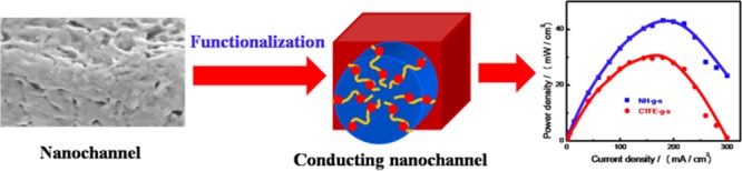
A fuel cell is an electrochemical converter that generates energy using chemical as the fuel. More specifically, a direct methanol fuel cell (DMFC) is a category of proton electrolyte membrane fuel cell that utilizes methanol as a fuel to produce electricity without the use of any reforming unit. Methanol is oxidized at the anode, generating protons, electrons, and carbon dioxide. The proton is transported through the polymeric electrolyte membrane from the anode to the cathode and then combines with oxygen and electron to complete the redox reaction following the membrane electrode assembly like the one give in Figure 6a. Proton transport through the membrane is very crucial for a fuel cell following hydration of the membrane electrode assembly (MEA). The performances of the polystyrene grafted and sulfonated specimens of CTFE copolymer and its nanohybrid membranes are measured by recording the polarization curves in DMFCs, which show a higher potential for nanohybrid vis-à-vis CTFE (Figure 6b). Open circuit voltage (OCV) is found to be 0.6 V for NH-g-s functionalized membrane, higher than the value of CTFE-g-s (0.53 V). Needless to mention that the standard Nafion membrane has the value of 0.68 V in a similar condition of measurement (Supporting Figure S5). Nyquist plot for the membranes (both functionalized pure polymer and nanohybrid) are shown in the Supporting Figure S12. High OCV value of NH as compared to CTFE membrane lies on greater sulfonation in the β-phase in the presence of nanoclay, which assists in better proton conduction through the ionic nanochannel and enhances the performance of the fuel cell. Direct methanol fuel cell performance using the conducting nanochannel membranes (CTFE-g-s and NH-g-s) demonstrates maximum power densities of 300 and 440 W m–2 at the current density of 3.0 × 10³ A m–2 (Figure 6b). A thinner membrane with lower resistance displays advanced fuel cell performance.51 Wootthikanokkhan et al. have reported the proton exchange membranes made by blending poly(vinylidene fluoride) with sulfonated poly(ether ether ketone) and applied in DMFC performance having thermal stability at high temperature.52
Figure 6.

(a) Membrane electrode assembly (MEA) pattern using grafted and functionalized membrane prepared through accelerator for the measurement of a direct methanol fuel cell (DMFC); the membranes used are CTFE-g-s and NH-g-s irradiated with Ag ions. (b) DMFC performance curves for MEAs made with indicated membranes. The efficacy of the nanohybrid membrane is higher than that of pure polymer.
Therefore, ion beam irradiation leads to the formation of free radicals in the polymer chains whose extent is higher in nanohybrid. The surface free radical gets oxidized with air, but the bulk free radicals remain active after etching to create the nanochannel. Those active radical can initiate grafting on CTFE/hybrid samples followed by ionomer formation. The selectivity parameters, the degree of sulfonation and water uptake, are considered for higher efficiency of fuel cell especially for nanohybrid, showing superior efficacy of the membrane for a fuel cell as compared to standard Nafion.
Conclusions
Nanometer dimension amorphous latent tracks have been created in CTFE copolymer and its hybrid with layered silicates by irradiating swift heavy ions. Through nanochannels are fabricated by selective etching of those amorphous tracks that are further grafted with polystyrene using the free radicals formed in the polymer chains during irradiation. The diameter of the nanochannels is varied from 30 to 100 nm using ions of different sizes (Li or Ag). Polystyrene graft within the nanochannels is functionalized to generate the sulfonate group exclusively within the nanochannels. The dimension of nanochannel is explored through SEM, TEM, and AFM micrographs, showing bigger size using silver ion for irradiation. Grafting and subsequent functionalization are confirmed through NMR, FTIR, and UV studies. Glass transition temperature of polystyrene graft within the confined space is measured by using DSC, and thermogravimetric studies indicate thermal stability of the membrane up to 200 °C. Nanoclay induces the piezoelectric β-phase in the polymer whose abundance becomes high after functionalization. Proton conductivity of the functionalized membrane is found to be very high (∼3.5 S m–1) due to the migration of protons through the hydrophilic conducting nanochannels. Higher conduction in silver-irradiated membrane as compared to that in lithium-irradiated membrane is due to the greater volume of the nanochannel higher degree of sulfonation using Ag as SHI. Methanol permeability, water uptake, and mechanical stability of the functionalized membrane are suitable for its application in fuel cell. Membrane electrode assembly (MEA) has been designed with the developed nanohybrid membranes and found to generate 440 W m–2 of power density at the current density of 3.0 × 10³ A m–2. So, the developed nanohybrid membrane has every quality to replace the standard membrane like Nafion.
Experimental Section
Materials
A commercial powdered SOLEF 31008, a copolymer of vinylidene fluoride and chlorotrifluoro ethylene, is used in this work and termed as CTFE afterward; it was kindly supplied by Ausimont, Italy (MFI: 15 g/10 min, @ 230 °C, 5 kg). Cloisite 30B [bis(hydroxyethyl) methyl tallow ammonium ion exchanged montmorillonite], Southern clay, CEC 110 mequiv/100 g is used as a nanofiller. (Tallow is a mixture of C16 and C18 long-chain alkenes.) Sodium hydroxide and potassium permanganate (NaOH, KMnO4), LOBA Chemie, are used as an etchant and potassium metabisulfite (K2S2O5, Sigma-Aldrich) is used for the cleaning purpose. Styrene monomer (Sigma-Aldrich) and toluene (LOBA Chemie) are used for grafting and distilled before polymerization. Chlorosulfonic acid (ClSO3H, LOBA Chemie) is used for sulfonation on grafted species.
Specimen Preparation
The CTFE nanohybrids are prepared through the solution route by dissolving CTFE in the dispersion of 4 wt % of nanofiller using dimethylformamide (DMF) solvent as reported in the literature.22 Henceforth, the nanohybrids will be designated as NH with 4 wt % of nanoclay in the polymer template. Detailed membrane preparation technique is reported in the literature.20
Membrane Preparation and Functionalization
The CTFE and its nanohybrid (NH) specimens of size 25 μm thick are placed on a ladder for irradiation in a vacuum chamber of 5 × 10⁻⁶ mbar in a Pelletron accelerator at the Inter University Accelerator Center, New Delhi, India. The films are then irradiated with heavy ions beams of 80 MeV Li3+ or 120 MeV Ag11+ ions separately with a ion fluence of 5 × 10⁷ ions cm–2 to ensure the effect of ion size on membrane properties. The energy of the beam is so chosen that the ions pass through the film without their implantation in the polymer matrix. For ion fluence, scattered ions from a thin gold foil (250 μg cm–2) in general purpose scattering chamber are used for the preparation of fuel cell membrane having the size of 4 × 4 cm2. To fabricate tracks, the irradiated CTFE and its nanohybrid films are chemically etched using a mixture of permanganate solution (0.25 mol L–1) and a highly alkaline medium (9 mol L–1) at 60 °C for 3 h and the etching and grafting procedure is followed from our previously reported literatures.21,35 Sulfonation of grafted CTFE and its NH film has been conducted in the presence of chlorosulfonic acid at 60 °C for 30 min. The sulfonated films are cleaned with deionized water until the residual water has a pH of 7 and the remaining water at the surface is absorbed with a filter paper and dried at 60 °C overnight under reduced pressure. Hereafter, the etched, etched + grafted, and etched + grafted + sulfonated specimens are designated as -e, -g, and -g-s, respectively. The water uptake of the functionalized membrane (4 × 4 cm2) is measured by immersing the membrane in deionized water at 25 °C for 24 h. Water swollen specimen was taken out, cleaned up with tissue paper, and instantly weighed. The water uptake of the prepared membranes is determined following eq 1 and has been taken as the average of three specimens
| 1 |
where Wwet and Wdry are the weights of water swollen and the dried membrane, respectively. Ion exchange capacity (IEC) was determined by equilibrating the membrane in 2.0 M HCl to convert the membrane into acidic form. The membrane was then washed with double distilled water and equilibrated to remove the last traces of acid. Then, it was equilibrated in 2.0 M NaCl for 24 h for ion exchange to take place. The remaining solution was titrated with 0.025 M NaOH solution using phenolphthalein as an indicator. The IEC values are calculated using eq 2
| 2 |
where VNaOH and SNaOH are the volume and molar concentration of NaOH solution used for titration, respectively. Wdry is the weight of the dried specimen.
Materials Characterization
The morphology of the porous membrane is explored using a scanning electron microscope (SUPRA 40, Zeiss) after gold coating by means of a sputtering apparatus, and the EDS mapping of different functionalized specimens have also been taken. Samples for transmission electron microscopy were taken using a TEM (Technai G2) at an accelerating voltage of 100 kV for CTFE films (etched and grafted specimens). NT-MDT multimode AFM, Russia, controlled by a Solver scanning probe microscope controller, was used to study the surface morphology of the membranes in a semicontact mode with the tip mounted on 100 μm long single cantilever with a resonant frequency in the range of 240–255 kHz and the corresponding spring constant of 11.5 N m–1. The current–voltage (I–V) characteristic of the specimen was measured using scanning tunneling microscopy mode attached to the AFM instrument. The samples were placed from −9 to +9 bias voltages at room temperature.
A method (three parallel cells) has been used for the gas permeabilities of neat CTFE and its NH membrane using pure nitrogen (N2) gas under constant pressure as described earlier in the literature.23 The detail procedure is given in the literature.35
The degree of sulfonation of the functionalized membranes was estimated through 1H NMR (in DMSO-d6 solvent) using a BRUKER spectrometer at room temperature. The degree of sulfonation DS (%) was evaluated from the ratio of integrals areas of the peaks, following eq 3
| 3 |
where X and Y are the integration areas of the peaks assigned as c, d, e, and a, b as mentioned in Figure 3a. Fourier transformed infrared (FTIR) spectrum was taken in the reflectance mode at room temperature from 400 to 4000 cm–1 using a Nicolet 6700 FTIR with a resolution of 4 cm–1. UV–visible (Jasco V-650) measurement was done in the range of 200–800 nm in the reflectance mode using solid specimens. Thermal decomposition tests of CTFE and its nanohybrid membranes were carried out with a thermogravimetric analyzer (TGA) (Mettler-Toledo). The TGA thermograms were recorded at a scan rate of 20 °C min–1 up to 600 °C in nitrogen atmosphere. The glass transition (Tg) and melting (Tm) temperature of the membranes were carried out on a differential scanning calorimeter (DSC) using a Mettler 832 instrument in the temperature range of 25–200 °C at a scan rate of 10° min–1 under N2 atmosphere.
X-ray diffraction (XRD) patterns were recorded using a Rigaku miniflex 600 X-ray diffractometer with the scanning rate of 2° min–1 at room temperature operating under a voltage of 40 kV and a current of 15 mA using Cu Kα radiation (λ = 1.54 Å).
Electrochemical Measurements
Conductance of functionalized membrane is carried out in humidified condition using alternating current impedance spectroscopy by a potentiostat/galvanostat frequency response analyzer (Auto Lab, model PGSTAT 30). Experimental details are reported in the literature.34 Temperature-dependent conductivity was measured in a wide range of temperature from 25 to 80 °C. The activation energy (Ea), the minimum energy required for the proton transport across the membrane, has been calculated using Arrhenius equation (eq 4)
| 4 |
where R is the universal gas constant (8.314 J mol–1 K–1) and T is the temperature in absolute scale (K).
Methanol cross-over of the graft and sulfonated specimen was measured from the refractive index measurement using a digital refractometer (Mettler Toledo RE40D). A diaphragm diffusion cell consisting of two compartments was fabricated following previously reported technique.24
The methanol permeability (P) was obtained from eq 5
| 5 |
where A is the effective membrane area, L is the thickness of the membrane, CB(t) the methanol concentration in compartment B at time t, CA(t – t0) is the change in the methanol concentration in compartment A between time 0 and t, and VB is the volume of compartment B. All of the tests were carried out at 30 °C. The inaccuracy of the measurement was less than 2%. Methanol permeability value was used to calculate the selectivity parameter (SP) using eq 6
| 6 |
where PMeOH is the methanol permeability (m2 s–1).
The membrane electrode assembly (MEA) was prepared by the earlier reported method and consisted of a three-layer structure (AM, anode/cathode catalyst layer and diffusion layers).25 MEA preparation procedure is being followed from our previously reported literature.34
Acknowledgments
The authors are thankful to the Director, Inter University Accelerator Centre (IUAC), New Delhi, India (project no. IUAC/XIII.7/UFR-47311) for swift heavy ion facility and other related logistic supports.
Supporting Information Available
The Supporting Information is available free of charge on the ACS Publications website at DOI: 10.1021/acsomega.7b01635.
Figure S1 describes the nanochannel distribution obtained from TEM and AFM images, whereas Figure S2 contains the UV–vis pattern of pure polystyrene; Figure S3 includes the deconvoluted XRD pattern indicating various peaks of CTFE and it nanohybrid; Figure S4 describes the regression curves (Arrhenius plot) of proton conductivity as a function of temperature; Figure S5 shows the DMFC performance of standard Nafion membrane; Figures S6–S16 present the EDS patterns different samples showing the presence of various elements; Table S1 summarizes the elemental details obtained from the EDS patterns; Figure S12, Nyquist plot of different functionalized CTFE and its nanohybrid (NH) (PDF)
The authors declare no competing financial interest.
Supplementary Material
References
- Moore R. B.; Martin C. R. Chemical and morphological properties of solution-cast perfluorosulfonate ionomers. Macromolecules 1988, 21, 1334–1339. 10.1021/ma00183a025. [DOI] [Google Scholar]
- Melchior J.-P.; Bräuniger T.; Wohlfarth A.; Portale G.; Kreuer K.-D. About the Interactions Controlling Nafion’s Viscoelastic Properties and Morphology. Macromolecules 2015, 48, 8534–8545. 10.1021/acs.macromol.5b01559. [DOI] [Google Scholar]
- Soles K. A.; Runt C. L. J.. Polymers for Energy Storage and Delivery: Polyelectrolytes for Batteries and Fuel Cells; ACS Symposium Series; American Chemical Society: Washington, DC, 2012; p 1096. [Google Scholar]
- Titvinidze G.; Kreuer K.-D.; Schuster M.; Araujo C. C. de; Melchior J. P.; Meyer W. H. Proton Conducting Phase-Separated Multiblock Copolymers with Sulfonated Poly(phenylene sulfone) Blocks for Electrochemical Applications: Preparation, Morphology, Hydration Behavior, and Transport. Adv. Funct. Mater. 2012, 22, 4456–4470. 10.1002/adfm.201200811. [DOI] [Google Scholar]
- Bae B.; Miyatake K.; Watanabe M. Synthesis, and Properties of Sulfonated Block Copolymers Having Fluorenyl Groups for Fuel-Cell Applications. ACS Appl. Mater. Interfaces 2009, 1, 1279–1286. 10.1021/am900165w. [DOI] [PubMed] [Google Scholar]
- Yang A. C. C.; Narimani R.; Zhang Z.; Frisken B. J.; Holdcroft S. Controlling Crystallinity in Graft Ionomers, and Its Effect on Morphology, Water Sorption, and Proton Conductivity of Graft Ionomer Membranes. Chem. Mater. 2013, 25, 1935–1946. 10.1021/cm4005932. [DOI] [Google Scholar]
- Monnin M. M.; Blanford G. E. Detection of Charged Particles by Polymer Grafting. Science 1973, 181, 743–744. 10.1126/science.181.4101.743. [DOI] [PubMed] [Google Scholar]
- Kulshrestha V.; Awasthi K.; Vijay Y. K. Swift heavy ion (SHI) irradiated polymer blend membranes for hydrogen permeation. Int. J. Hydrogen Energy 2007, 32, 3105–3108. 10.1016/j.ijhydene.2007.01.014. [DOI] [Google Scholar]
- Clochard M. C.; Berthelot T.; Baudin C.; Betz N.; Balanzat E.; Gébel G.; Morin A. Ion track grafting: A way of producing low-cost and highly proton conductive membranes for fuel cell applications. J. Power Sources 2010, 195, 223–231. 10.1016/j.jpowsour.2009.07.016. [DOI] [Google Scholar]
- Bessbousse H.; Zran N.; Fauléau J.; Godin B.; Lemée V.; Wade T.; Clochard M. C. Poly(4-vinyl pyridine) radiografted PVDF track etched membranes as sensors for monitoring trace mercury in water. Radiat. Phys. Chem. 2016, 118, 48–54. 10.1016/j.radphyschem.2015.03.011. [DOI] [Google Scholar]
- Tiwari V. K.; Kulriya P. K.; Avasthi D. K.; Maiti P. Radiation-Resistant Behavior of Poly(vinylidene fluoride)/Layered Silicate Nanocomposites. ACS Appl. Mater. Interfaces 2009, 1, 311–318. 10.1021/am800040q. [DOI] [PubMed] [Google Scholar]
- Lee E. H. Ion-beam modification of polymeric materials-fundamental principles and applications. Nucl. Instrum. Methods Phys. Res., Sect. B 1999, 151, 29–41. 10.1016/S0168-583X(99)00129-9. [DOI] [Google Scholar]
- Bergman J. G. Jr.; McFee J. H.; Crane G. R. Pyroelectricity and Optical Second Harmonic Generation in Polyvinylidene Fluoride Films. Appl. Phys. Lett. 1971, 18, 203 10.1063/1.1653624. [DOI] [Google Scholar]
- Fukada E.; Sakurai T. Piezoelectricity in Polarized Poly(vinylidene fluoride) Films. Polym. J. 1971, 2, 656–662. 10.1295/polymj.2.656. [DOI] [Google Scholar]
- Ying L.; Wang P.; Kang E. T.; Neoh K. G. Synthesis and Characterization of Poly(acrylic acid)-graft-poly(vinylidene fluoride) Copolymers and pH-Sensitive Membranes. Macromolecules 2002, 35, 673–679. 10.1021/ma0112568. [DOI] [Google Scholar]
- Aoshima R.; Kanda Y.; Takada A.; Yamashita A. Sulfonated poly(vinylidene fluoride) as a biomaterial: immobilization of urokinase and biocompatibility. J. Biomed. Mater. Res. 1982, 16, 289–99. 10.1002/jbm.820160309. [DOI] [PubMed] [Google Scholar]
- Chang Y.; Shih Y.-J.; Ko C.-Y.; Jhong J.-F.; Liu Y.-L.; Wei T.-C. Hemocompatibility of Poly(vinylidene fluoride) Membrane Grafted with Network-Like and Brush-Like Antifouling Layer Controlled via Plasma-Induced Surface PEGylation. Langmuir 2011, 27, 5445–5455. 10.1021/la1048369. [DOI] [PubMed] [Google Scholar]
- Boschet F.; Ameduri B. (Co)polymers of Chlorotrifluoroethylene: Synthesis, Properties, and Applications. Chem. Rev. 2014, 114, 927–980. 10.1021/cr2002933. [DOI] [PubMed] [Google Scholar]
- Lovinger A. J. Ferroelectric polymers. Science 1983, 220, 1115–21. 10.1126/science.220.4602.1115. [DOI] [PubMed] [Google Scholar]
- Jana K. K.; Ray B.; Avasthi D. K.; Maiti P. Conducting nano-channels in an induced piezoelectric polymeric matrix using swift heavy ions and subsequent functionalization. J. Mater. Chem. 2012, 22, 3955–3964. 10.1039/c2jm15132d. [DOI] [Google Scholar]
- Jana K. K.; Thakur A. K.; Shahi V. K.; Avasthi D. K.; Rana D.; Maiti P. A poly(vinylidene fluoride-co-hexafluoro propylene) nanohybrid membrane using swift heavy ion irradiation for fuel cell applications. J. Mater. Chem. A. 2015, 3, 10413–10424. 10.1039/C5TA01398D. [DOI] [Google Scholar]
- Tiwari V. K.; Prasad A. K.; Singh V.; Jana K. K.; Misra M.; Prasad C. D.; Maiti P. Nanoparticle and Process Induced Super Toughened Piezoelectric Hybrid Materials: The Effect of Stretching on Filled System. Macromolecules 2013, 46, 5595–5603. 10.1021/ma400603h. [DOI] [Google Scholar]
- Savoji H.; Rana D.; Matsuura T.; Soltanieh M.; Tabe S. Novel Surface Modifying Macromolecules (SMMs) Blended Polysulfone Gas Separations Membranes by Phase Inversion Technique. J. Appl. Polym. Sci. 2012, 124, 2287–2299. 10.1002/app.34809. [DOI] [Google Scholar]
- Nagarale R. K.; Gohil G. S.; Shahi V. K. Sulfonated poly(ether ether ketone)/polyaniline composite proton-exchange membrane. J. Membr. Sci. 2006, 280, 389–396. 10.1016/j.memsci.2006.01.043. [DOI] [Google Scholar]
- Tripathi B. P.; Chakrabarty T.; Shahi V. K. Highly Charged and Stable Cross-linked 4,4/- bis(4-aminophenoxy)biphenyl-3,3/-disulfonic acid (BAPBDS)-sulfonated poly(ether sulfone) Polymer electrolyte Membranes Impervious to Methanol. J. Mater. Chem. 2010, 20, 8036–8044. 10.1039/c0jm01183e. [DOI] [Google Scholar]
- Trautmann C.; Bouffard S.; Spohr R. Etching threshold for ion tracks in polyimide. Nucl. Instrum. Methods Phys. Res., Sect. B 1996, 116, 429–433. 10.1016/0168-583X(96)00083-3. [DOI] [Google Scholar]
- Tiwari V. K.; Shripathi T.; Lalla N. P.; Maiti P. Nanoparticle Induced Piezoelectric, Super Toughened, Radiation Resistant, Multi-functional Nanohybrids. Nanoscale 2012, 4, 167–175. 10.1039/C1NR11009H. [DOI] [PubMed] [Google Scholar]
- Tiwari V. K.; Singh N. K.; Avasthi D. K.; Misra M.; Maiti P. Swift heavy ions induced controlled biodegradation of poly(ε-caprolactone) Nanohybrids. Radiat. Phys. Chem. 2013, 82, 92–99. 10.1016/j.radphyschem.2012.09.006. [DOI] [Google Scholar]
- Jana K. K.; Vishwakarma N. K.; Ray B.; Khan S. A.; Avasthi D. K.; Misra M.; Maiti P. Nanochannel Conduction in Piezoelectric Polymeric Membrane using Swift Heavy Ions and Nanoclay. RSC Adv. 2013, 3, 6147–6159. 10.1039/c3ra23176c. [DOI] [PMC free article] [PubMed] [Google Scholar]
- Betz N.; Moel A. L.; Duraud J. P.; et al. Grafting of polystyrene in poly(vinylidene fluoride) films by means of energetic heavy ions. Macromolecules 1992, 25, 213–219. 10.1021/ma00027a036. [DOI] [Google Scholar]
- Müller F.; Ferreira C. A.; Franco L.; Puiggalí J.; Aleman C.; Armelin E. New Sulfonated Polystyrene and Styrene-Ethylene/Butylene-Styrene Block Copolymers for Applications in Electrodialysis. J. Phys. Chem. B 2012, 116, 11767–11779. 10.1021/jp3068415. [DOI] [PubMed] [Google Scholar]
- Martins P.; Lopes A. C.; Lanceros-Mendez S. Phases of poly(vinylidene fluoride): Determination, processing, and applications. Prog. Polym. Sci. 2014, 39, 683–706. 10.1016/j.progpolymsci.2013.07.006. [DOI] [Google Scholar]
- Hester J. F.; Banerjee P.; Won Y. Y.; Akthakul A.; Acar M. H.; Mayes A. M. ATRP of Amphiphilic Graft Copolymers Based on PVDF and Their Use as Membrane Additives. Macromolecules 2002, 35, 7652–7661. 10.1021/ma0122270. [DOI] [Google Scholar]
- Jana K. K.; Charan C.; Shahi V. K.; Mitra K.; Ray B.; Rana D.; Maiti P. Functionalized poly(vinylidene fluoride) nanohybrid for superior fuel cell membrane. J. Membr. Sci. 2015, 481, 124–136. 10.1016/j.memsci.2015.01.053. [DOI] [Google Scholar]
- Jana K. K.; Srivastava A.; Parkash O.; Avasthi D. K.; Rana D.; Shahi V. K.; Maiti P. Nanoclay and swift heavy ions induced piezoelectric and conducting nanochannel based polymeric membrane for fuel cell. J. Power Sources 2016, 301, 338–347. 10.1016/j.jpowsour.2015.10.020. [DOI] [Google Scholar]
- Tiwari V. K.; Kulriya P. K.; Avasthi D. K.; Maiti P. Poly(Vinylidene fluoride-cohexafluoro propylene)/Layered Silicate Nanocomposites: The Effect of Swift Heavy Ion. J. Phys. Chem. B 2009, 113, 11632–11641. 10.1021/jp904907y. [DOI] [PubMed] [Google Scholar]
- Shi Z.; Holdcroft S. Synthesis and Proton Conductivity of Partially Sulfonated Poly([vinylidene difluoride-co-hexafluoropropylene]-b-styrene) Block Copolymers. Macromolecules 2005, 38, 4193–4201. 10.1021/ma0477549. [DOI] [Google Scholar]
- Rana D. S.; Chaturvedi D. K.; Quamara J. K. Nano/micro surface structural study of swift heavy ions irradiated PVDF Films by AFM. Optoelectron. Adv. Mater., Rapid Commun. 2009, 3, 737–743. [Google Scholar]
- Maiti P.; Nandi A. K. Morphology of Poly(vinylidene fluoride)/ Poly(methyl acrylate) Blends: Influence of Chain Structure. Macromol. Chem. Phys. 1998, 199, 1479–1484. . [DOI] [Google Scholar]
- Gaur A.; Shukla R.; Brajesh K.; Pal A.; Chatterji S.; Ranjan R.; Maiti P. Processing and nanoclay induced piezoelectricity in poly(vinylidene fluoride-co-hexafluoro propylene) nanohybrid for device application. Polymer 2016, 97, 362–369. 10.1016/j.polymer.2016.05.049. [DOI] [Google Scholar]
- Gupta M.; Lin Y.; Deans T.; Baer E.; Hiltner A.; Schiraldi A. Structure and Gas Barrier Properties of Poly(propylene-graft-maleic anhydride)/Phosphate Glass Composites Prepared by Microlayer Coextrusion. Macromolecules 2010, 43, 4230–4239. 10.1021/ma100391u. [DOI] [Google Scholar]
- Martins P.; Larrea A.; Goncalves R.; Botelho G.; Ramana E. V.; Mendiratta S. K.; Sebastian V.; Lanceros-Mendez S. Novel Anisotropic Magnetoelectric Effect on δ-FeO(OH)/P(VDF-TrFE) Multiferroic Composites. ACS Appl. Mater. Interfaces 2015, 7, 11224–11229. 10.1021/acsami.5b01196. [DOI] [PubMed] [Google Scholar]
- Tiwari V. K.; Avasthi D. K.; Maiti P. Swift Heavy Ion Induced Ordering and Piezoelectric β-phase in Poly(vinylidene fluoride). ACS Appl. Mater. Interfaces 2011, 3, 1398–1401. 10.1021/am200293g. [DOI] [PubMed] [Google Scholar]
- Garain S.; Sinha T. K.; Adhikary P.; Henkel K.; Sen S.; Ram S.; Sinha C.; Schmeißer D.; Mandal D. Self-Poled Transparent and Flexible UV Light-Emitting Cerium Complex–PVDF Composite: A High-Performance Nanogenerator. ACS Appl. Mater. Interfaces 2015, 7, 1298–1307. 10.1021/am507522r. [DOI] [PubMed] [Google Scholar]
- Tsang E. M. W.; Zhang Z.; Shi Z.; Soboleva T.; Holdcroft S. Considerations of Macromolecular Structure in the Design of Proton Conducting Polymer Membranes: Graft versus Diblock Polyelectrolytes. J. Am. Chem. Soc. 2007, 129, 15106–15107. 10.1021/ja074765j. [DOI] [PubMed] [Google Scholar]
- Schmidt-Rohr K.; Chen Q. Parallel cylindrical water nanochannels in Nafion fuel-cell membranes. Nat. Mater. 2008, 7, 75–83. 10.1038/nmat2074. [DOI] [PubMed] [Google Scholar]
- Gubler L.; Gursel S. A.; Scherer G. G. Radiation Grafted Membranes for Polymer Electrolyte Fuel Cells. Fuel Cells 2005, 5, 317–335. 10.1002/fuce.200400078. [DOI] [Google Scholar]
- Tripathi B. P.; Shahi V. K. 3-[[3-(Triethoxysilyl) propyl] propane-1-sulfonic acid- Poly(vinyl alcohol) Cross-Linked Zwitterionic Polymer Electrolyte Membranes for Direct Methanol Fuel Cell Applications. ACS Appl. Mater. Interfaces 2009, 1, 1002–1012. 10.1021/am800228s. [DOI] [PubMed] [Google Scholar]
- Varcoe J. R.; Slade R. C. T.; Yee E. L. H.; Poynton S. D.; Driscoll D. J.; Apperley D. C. Poly(ethylene-co-tetrafluoroethylene)-Derived Radiation-Grafted Anion-Exchange Membrane with Properties Specifically Tailored for Application in Metal-Cation-Free Alkaline Polymer Electrolyte Fuel Cells. Chem. Mater. 2007, 19, 2686–2693. 10.1021/cm062407u. [DOI] [Google Scholar]
- Hasani-Sadrabadi M. M.; Emami S. H.; Ghaffarian R.; Moaddel H. Nanocomposite Membranes Made from Sulfonated Poly(ether ether ketone) and Montmorillonite Clay for Fuel Cell Applications. Energy Fuels 2008, 22, 2539–2542. 10.1021/ef700660a. [DOI] [Google Scholar]
- Rozière J.; Jones D. J. Non-fluorinated polymer materials for proton exchange membrane fuel cells. Annu. Rev. Mater. Res. 2003, 33, 503–55. 10.1146/annurev.matsci.33.022702.154657. [DOI] [Google Scholar]
- Wootthikanokkhan J.; Seeponkai N. Methanol Permeability and Properties of DMFC Membranes based on Sulfonated PEEK/PVDF Blends. J. Appl. Polym. Sci. 2006, 102, 5941–5947. 10.1002/app.25151. [DOI] [Google Scholar]
Associated Data
This section collects any data citations, data availability statements, or supplementary materials included in this article.