Abstract
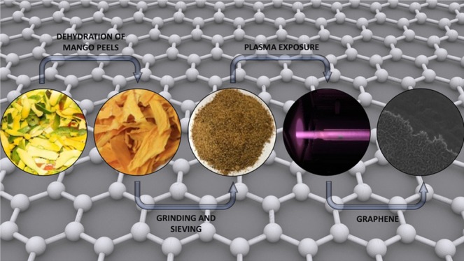
The excess of mango peels is considered manufacturing waste in the sugar and juice industry. There is an increasing interest in looking for alternative ways to employ this waste to address this overload. Here, we show the efficient use of mango peels as a noncost carbon source for the synthesis of graphene. We demonstrate for the first time the synthesis of graphene on Cu substrates from mango peels, a biomass rich in pectin. It is observed that plasma presence is essential for the growth of graphene from mango peels. At 15 and 30 min of plasma exposure, we observed the presence of multilayered graphene, at longer plasma exposure, i.e., 60 min, there is the formation of monolayer graphene, attributed to the etching of multiple layers formed at short times due to long plasma exposure time. When employing this technique, precautions must be taken due to the etching effect of plasma, such as reducing either the plasma exposure time or the plasma power. Finally, we present a graphene growth pathway under plasma environment on the basis of our experimental observations.
Introduction
Pectin-rich biomass is considered as an under-utilized waste product of the sugar and juice industry; however, recently, they have gained attention as feedstock for the synthesis of high-value chemicals, especially liquid fuels.1,2 Mango puree, slices in sirup, nectar, canned juices, and preserves are the main industrial products obtained from mango fruit. The major byproduct is peels and represents around 24% of the total weight of the fruit.3
Mango peel is a biomass rich in pectin that also contains cellulose, hemicellulose, lipids, protein, and enzymes.4−6 Mexico, as one of the top five countries that produces, exports, and imports mango,7,8 produces an excessive amount of this waste product. The mango peels that are mainly considered industrial waste are either employed for compost or sold at a low value as animal feed.9 Hence, there is a necessity to alleviate the accumulation of mango peels in several regions of Mexico.
Herein, we demonstrate for the first time the feasibility of producing graphene as a high-value material from mango peels using plasma. Graphene is an allotropic form of carbon. The structure of graphene is formed by six-membered carbon rings connected to each other. Each carbon atom is in sp2 hybridization state10 and shares σ-bond (s, px, and py) with three adjacent carbon atoms and one π-bond in the pz orbital above the two-dimensional (2D) structural plane.11 The C–C bond length is 1.41 Å, with a bond angle of 120° in its structure.12 Graphene sheets have found multiple uses, such as catalyst,13−19 semiconductor,20 light-emitting diodes,21 supercapacitors,22 lithium-ion batteries,23 sensors,24 and water treatment.25 Graphene exhibits a surface area higher than 2500 m2 g–1,26 which is at least thrice the amount of any other allotrope of carbon. Furthermore, graphene’s unique optoelectrical properties are a result of its zero band gap,27 which makes it extremely useful in sensors, LEDs, transistors, and other electrical devices. As for any material, a clear specification is paramount to a successful material application. For our purposes, it is important to distinguish between single-layer and multilayer graphene. Both of these types of graphene have very different properties. Unlike single-layer graphene, multilayer graphene does not have zero band gap, which makes it more suitable for semiconductor applications.28 Furthermore, multilayer graphene provides better corrosion resistance.29 For the case of single-layer graphene, the electron mobility increases at lower temperatures, making it a better superconductor.30
Typically, the growth of graphene has been performed with thermal chemical vapor deposition (CVD) by catalytic dehydrogenation of carbon precursors, most commonly by methane on copper.27 However, this technique is limited by the need of high temperatures (≈1000 °C) and in many cases, multiple processing steps. In a conventional CVD process, the time needed to obtain a high-quality graphene layer synthesized from biomass can take as long as 24 h.31
A promising approach for fast graphene synthesis at lower temperatures is the combined use of a metal such as Cu and plasma (“plasma-enhanced CVD” or PE-CVD). Plasma provides a rich gas chemistry environment that includes radicals, ions, and molecules from a simple carbon–hydrogen source, allowing a faster growth at lower temperatures. The plasma catalysis approach not only leads to the growth of high-quality graphene at low temperatures32,33 (<400 °C) but also is simpler by allowing a “one pot” synthesis by the in situ removal of native metal oxides due to the presence of hydrogen plasma. Furthermore, the plasma catalysis technique offers the advantage of ultrafast deposition, reducing the process time to a few minutes when using a simple carbon source such as methane, compared to that in the traditional CVD approach.32−34Table 1 summarizes the efforts done up to date for the synthesis of graphene using plasma. As can be observed, the main source of carbon employed is methane and the most common plasma discharges are microwave and radio frequency. In the proposed synthesis method, we employed Cu as the substrate because it can be observed in Table 1 as the most common substrate employed for the synthesis of graphene. Besides, it is cheaper compared to other employed substrates such as Ni. Furthermore, the solubility of carbon in Ni is higher compared to that of Cu,35 which requires very specific reaction conditions.
Table 1. Synthesis of Graphene Using Plasmas, State of the Art.
| plasma discharge | plasma power | carbon source [substrate] | temperature | time | reference |
|---|---|---|---|---|---|
| microwave | 2 kW | methane [quartz, Si, Ni, Pt, Ge, Ti, W, stainless steel, Ta, Mo] | 700 °C | 1–3000 s | (36) |
| 250 W | ethanol [unsupported] | 0.1 s (residence time) | (37) | ||
| 400–900 W | ethanol [unsupported] | 1300–2000 K | (38) | ||
| 1400 W | methane [Ni] | 450–750 °C | (39) | ||
| 3–4.5 kW | methane [Cu, Al] | 400 °C | 30–180 s | (40) | |
| 12–18 kW | methane [Cu, Al] | 320 °C | (41) | ||
| 6 kW | methane [quartz, Pt, Si] | 700 °C | 10–1200 s | (42) | |
| radio frequency | 13.56 MHz | methane [Cu] | 800–1000 °C | 30 s | (43) |
| 80 W | methane [Cu, glass, Si/SiO2] | 400–700 °C | 30–120 min | (44) | |
| 200 W | methane [Co on Si wafer] | 800 °C | 40 s | (45) | |
| 13.56 MHz | methane [Ni on Si] | 650 °C | 30 s | (46) | |
| 50–600 W | methane [Cu] | 950 °C | 5 s–60 min | (47) | |
| 300 W | methane [Cu] | 500 °C | 5 min | (48) |
Several efforts have been made using different sources of carbon. However, to the best of our knowledge, none were with the use of plasma. Among the different sources of carbon employed up to date are recycling waste plastic,49 cookie, chocolate, grass, plastic, dog feces and cockroach leg,31 and waste chicken fat,50 mostly performed by CVD at temperatures ranging from 1020 to 1080 °C. Graphene has also been prepared from chemical treatment and combustion of rice husk without any substrate.51,52 The use of mango (Mangifera indica) leaves has been reported for the synthesis of graphene quantum dots (QDs). The preparation of QDs was performed by treatment of extract obtained from tiny pieces of leaves stirred in ethanol. The conversion to QDs took place in a microwave oven at 900 W in a time-span of 5 min.53 However, the use of mango peels as a cheap source of carbon has not been explored yet. Herein, we demonstrate the successful synthesis of graphene from mango peels via plasma. To our best knowledge, this is the first time that graphene is obtained from this kind of biomass when using plasma.
Characterization
Raman spectroscopy was performed on graphene with a WiTec Alpha Scanning Near-Field Optical Microscope equipped with a 514 nm laser.
The thermogravimetric analysis (TGA) was performed on a Perkin Elmer Pyris 1 Thermogravimetric Analyzer, with the temperature ramp of 25 °C min–1 from 50 to 750 °C (reaction temperature) and a hold time of 12 min at 750 °C. The analysis was performed in a helium flow of 60 mL min–1.
The morphology of these materials was studied using transmission electron microscopy (TEM). The samples were prepared by dispersing them on 300 mesh lacey carbon copper-supported TEM grids and then were studied using a field emission gun FEI Tecnai F20 electron microscope operated at the accelerating voltage of 200 kV.
Results and Discussion
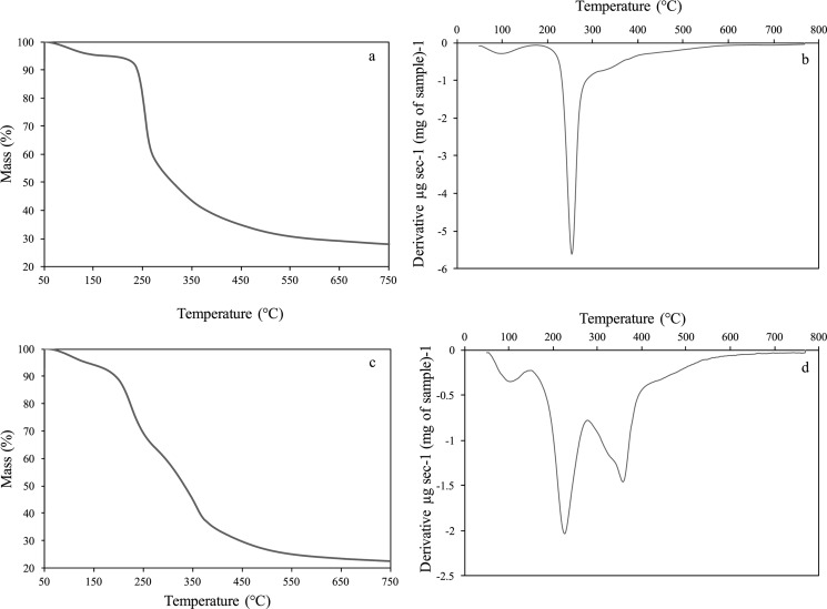
The TGA analysis of the mango peel M. indica L., type kent, and reference pectin (from citrus, VWR) is shown in Figure 1. Figure 1a,b shows the commercial pure pectin (from citrus, VWR) thermogravimetric analysis for comparison purposes. As mentioned before, mango peels have several components, such as lignocellulosic structures (cellulose, hemicellulose, and lignin) and pectin. The mango peel (M. indica L.), type kent, is considered a biomass rich in pectin (>12% dry base21). Figure 1c,d shows the TGA analysis for the mango peels. It is possible to observe an initial decomposition at around 100 °C, which is due to the water evaporation. Then, there is a second important weight loss at around 200 °C that can be attributed to the pectin because it is the less thermally stable polysaccharide. Furthermore, there is a weight reduction trend attributed to the cellulose and hemicellulose depolymerization54−56 [cellulose at 364 °C, (see Figure S1, Supporting Information) and hemicellulose at 320–340 °C57].
Figure 1.
TGA analysis for commercial pectin: (a) temperature vs mass % and (b) temperature vs derivative. TGA analysis for mango peels: (c) temperature vs mass % and (d) temperature vs derivative.
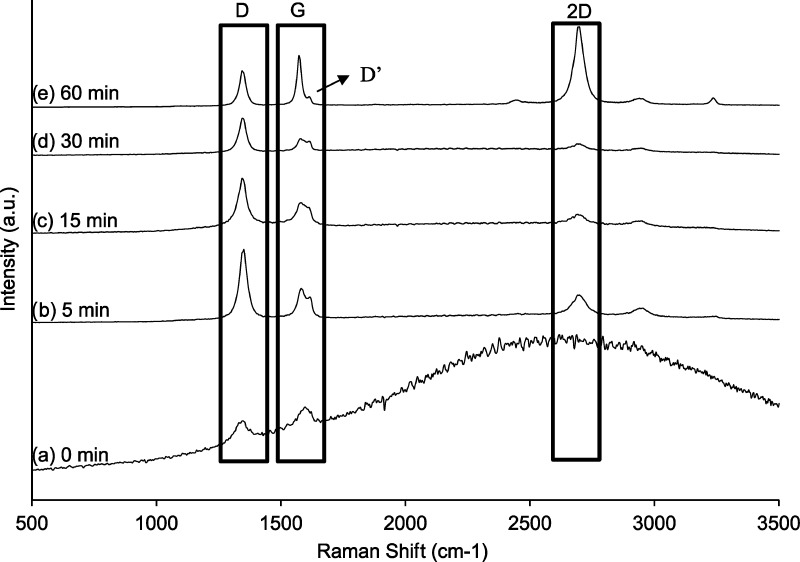
To investigate the synthesized graphene samples, we performed Raman analysis. The Raman spectra of all of the graphene-supported copper samples is shown in Figure 2. First, it is important to notice that during the 15 min of pretreatment at 750 °C with no plasma, i.e., the 0 min plasma sample, there is no graphene formation and only amorphous carbon is detected.58 Furthermore, none of the samples show any C–O or C=O vibration bands, which is the evidence of no oxygen present in the film. The mass of the substrate before and after the reaction was almost identical, which points toward etching or removal of most carbon by carrier gas during the plasma growth. It is postulated that the hydrogen content in the gas phase plays the dual role of an etchant as well as a reducing agent for the biomass. Argon merely behaves as a carrier. However, the presence of Argon in high concentration is necessary. If the ion density of hydrogen radicals is high, then there will be a competing reaction between adsorption of hydrogen35,59−62 and carbon deposition in the voids on the substrate surface. The signature peaks of graphene are the G and 2D (conventionally known as G′ band) presented at 1580 and 2690–2700 cm–1, respectively, in our case. These two bands together are the characteristic of sp2-hybridized carbon. The G peak is a result of first-order Raman scattering, whereas the 2D peak is a result of second order, i.e., two symmetrical phonons (K and K′) that contribute to the double resonance process. The G band is a Raman-allowed first-order frequency. The D-band at 1343–1347 cm–1 along with D′ band, which can be defined as a shoulder of D band, is a result of disorientations, disorder, and defects in the graphene structure.58,63,64
Figure 2.
Raman spectra of graphene samples as a function of the plasma exposure time (a) 0 min, (b) 5 min, (c) 15 min, (d) 30 min, and (e) 60 min.
Figure 2a shows the Raman analysis for the sample that was not exposed to plasma. For this sample, the D and G bands are very short but are visible, whereas the 2D peak is absent, indicating that the carbon is present in amorphous phase,61 which is well in agreement with the high background noise. The D-peak that is attributed to disorder and defects clearly reduces from 5 to 30 min of plasma exposure. Then, it seems to remain constant after 30 min of plasma exposure. This can be attributed to the growth kinetics. We hypothesized that as the time progresses from 5 to 30 min, individual nucleation islands begin to interconnect, leading to a reduction of defects and disorientations. The G-band peak shape changes with time too, which is an indication of structure formation. At 5 min of plasma treatment (Figure 2b), it is possible to distinguish the presence of G and D′ bands but as the time of plasma exposure increases, the G band increases, whereas the D′ band is almost indistinguishable, which points out a reduction in disorientation as the synthesis time increases. Finally, the evolution of the 2D band is very evident with the increase in plasma exposure time (Figure 2b–e). This can be explained by the interconnection of individual islands after 30 min, leading to the formation of a continuous coverage, hence increasing the intensity of the 2D band greatly.
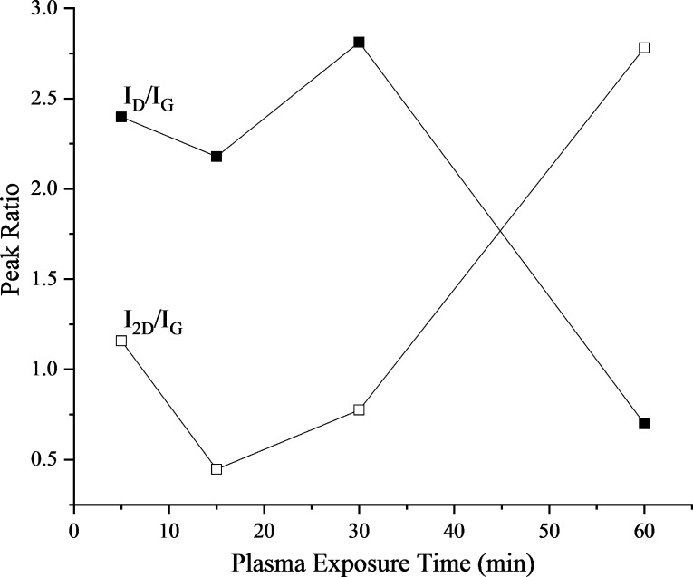
The intensity ratios of the D and G band can shed some light about the defects in graphene, whereas the intensity ratio of 2D and G bands can give important information about the number of layers in the sample.65,66 The intensity ratio ID/IG was calculated on the basis of peaks’ heights, whereas for I2D/IG, it was calculated on the basis of the peak areas using Origin Pro (Figure 3). In this case, two different approaches were employed due to the presence of the G(D′) shoulder. The intensity ratio ID/IG agrees to the aforementioned explanation of growth kinetics. As the treatment time increases, the defects decrease due to nucleation and then joining of the individual nucleation islands. More interestingly, the I2D/IG ratio provides a deep insight for understanding the growth kinetics at a later phase. At 5 min, the peak ratio I2D/IG is nearly 1.16, which is the ratio for double-layer graphene. From 5 to 15 min, the formation of nucleation islands seems to take place. After 15 min, the nucleation islands start getting connected through the surface and form a few layers of graphene. With further increase in the plasma exposure time, the layers of graphene start getting etched by the high density of hydrogen radicals due to the plasma presence. The effect of C etching by H atoms in plasma has been observed either at longer exposure times or at very high plasma powers.47 At 60 min, the intensity ratio I2D/IG is 2.78, which points toward the formation of single-layer graphene from few-layer graphene.58,61−63,65 In the plasma process presented here, it is clear that multiple graphene layers are generated at first and then get etched by the high concentration of atomic hydrogen from plasma, leading to single-layer graphene as the plasma exposure time increases.
Figure 3.
Evolution of peak ratios ID/IG and I2D/IG with plasma exposure time.
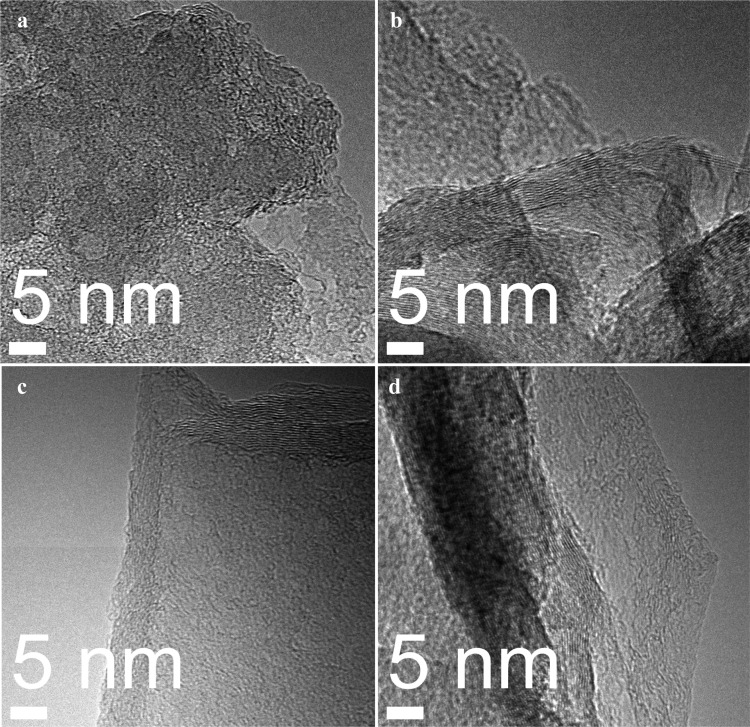
The morphology of the synthesized graphene was studied using transmission electron microscopy (TEM). The high-resolution transmission electron microscopy (HRTEM) images are shown in Figure 4. Figure 4a shows the image for 5 min plasma exposure, which corresponds to the peak ratio I2D/IG ∼ 1.16 for double-layer graphene. Figure 4b shows the TEM image for the sample exposed 15 min to plasma. This image shows an increase of graphene layers with respect to the 5 min plasma exposure sample. In Figure 4b, several graphene layers are overlapping each other. The presence of few layers of graphene was also confirmed by the Raman peak intensity ratio. Figure 4c shows the sample exposed for 30 min to plasma. Here, the layers of graphene have decreased as the treatment time increased from 15 to 30 min, making visible the fact that etching due to the presence of hydrogen atoms is becoming important with increase in plasma exposure time and it is overcoming the graphene deposition. In Figure 4d, a single-layer graphene is visible with some dark zones. Raman spectroscopy confirmed the presence of single-layered graphene (intensity ratio I2D/IG ∼ 2.78). The dark zones in this sample can be attributed to the wrinkles formed during the transfer of graphene from the copper substrate to the TEM grids.
Figure 4.
HRTEM images for synthesized graphene using different plasma exposure times: (a) 5 min, (b) 15 min, (c) 30 min, and (d) 60 min.
It is observed from our experiments that 60 min of plasma exposure time yields to a monolayer graphene. The conclusion is drawn from the intensity ratio obtained from the analysis of Raman spectra (Figure 3).
Compared to the conventional CVD process, in the plasma synthesis approach, the gas is in the ionized state with much higher ion density, which leads to faster reactions.67 Also, it has been reported that the localized ion and electron temperatures in plasma are higher than 1350 K.68−70 This results in the increase of localized temperature of the substrate surface due to electron and ion collisions, which reduces the amount of external energy that needs to be provided compared to that in the conventional CVD process. However, precautions must be taken due to the etching effect of plasma. It has been observed, when using methane as a carbon source, that longer exposure times can create higher defects and in some cases, convert the graphene to single-walled nanotubes.48 In our case, at longer times (120 min), dense deposits of carbon and “holes” on the surface were observed. A representative scanning electron microscopy image of a sample synthesized at 120 min is shown in Figure S3, Supporting Information. The phenomenon is a result of etching of C atoms from the surface. This can be avoided by limiting the synthesis time in an optimized range. Furthermore, if the plasma power is too high, it can lead to very high localized temperature, which can cause plasmic damage, creating lattice defects.43
Proposed Graphene Growth Pathway under Plasma Environment
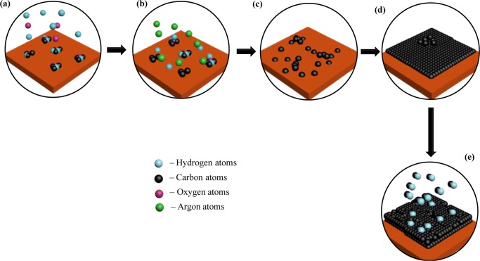
A few remarks first need to be made to describe the possible growth pathway for graphene in the presence of plasma from mango peels. First, the substrate employed was copper, which exhibits a high lattice parameter mismatch compared with graphene. Also, the solubility of carbon in copper is very less as compared to that of other metals employed for this purpose such as Nickel.71 Moreover, it does not form a carbide with carbon, which makes it different from other metal catalysts, like nickel,51 cobalt,45 and platinum.36 Because of these features, copper follows a different mechanism than that of its fellow transition metals.46 These properties of copper can also be attributed to its place in the periodic table (electronic configuration), which is just before that of the semimetals. As a result, it shares major chemical and physical properties with not only transition metals but also with semimetals. The proposed steps involved in the plasma synthesis of graphene on copper from mango peels can be described as follows (Figure 5):
-
(a)
As the temperature increases to 750 °C in the absence of plasma, the biomass is undergoing pyrolysis, breaking of the C–O, C=O, and C–H bonds, due to thermal energy. During this pyrolysis step also occurs intra and intermolecular rearrangement reactions that could lead to the formation of fairly big molecules72 that could not favor the growth of graphene (for this reason, several reports have proposed the use of a second pyrolysis for the synthesis of graphene oxides).73
-
(b)
Once plasma is on, it serves two functions: The substrate is cleaned by hydrogen radicals etching (removal of native oxides) for better exposure of metal sites and yields to the formation of the carbon ions/radicals.
-
(c)
The carbon atoms/ions/radicals get deposited in the voids of the face-centered cubic structure of copper surface unit cells (it does not penetrate inside the structure due to the low solubility).
-
(d)
The deposited carbon then forms bonds with nearby carbon atoms, forming nucleation islands that then get connected as the synthesis progresses with time. This represents the nucleation and growth steps (here, the growth of several graphene layers occurs).
-
(e)
At longer times, the top layers in the structure start getting etched by the hydrogen radicals in plasma.
Figure 5.
Graphene growth proposed pathway under plasma environment. (a) C–O, C=O, and C–H bond breaking due to thermal energy (b) H atoms generated by plasma adsorbed on Cu substrate to etch the surface while they also reduce more stable C–O and C=O bonds, whereas Ar atoms act as carrier (c) carbon atoms forming nucleation islands on the substrate surface and mitigating on the surface (d) formation of the graphene layer by bond between nucleation islands, whereas the excess carbon atoms start forming another layer on top (e) etching of top layers by hydrogen atoms generated by plasma to form single-layered graphene at long plasma exposure times.
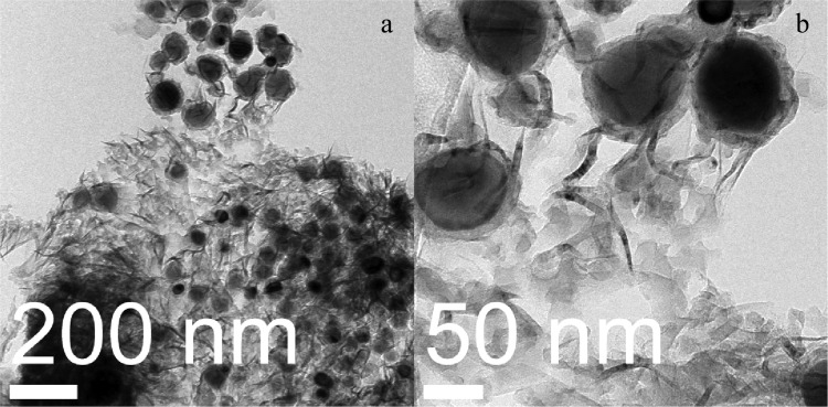
To observe the nucleation islands formation, we performed TEM analysis on the sample exposed to plasma for 15 min. Figure 6 shows the TEM images for this particular sample. The darker zones in these images are the nucleation islands with high density of carbon atoms which distribute themselves to form a film (lighter zones). This supports our proposed growth mechanism for graphene from solid source (mango peels). The dense black regions are a result of agglomerated reduced carbon from biomass reduction.
Figure 6.
TEM images of a sample exposed to 15 min of plasma treatment. The growth of films (lighter zones) from islands (darker zones) is evident.
Conclusions
Herein, we demonstrate the synthesis of graphene from mango peels using plasma on Cu substrates. This process represents a very promising alternative for the use of excessive mango peels produced by the food industry. The synthesis of multiple- and single-layer graphene is demonstrated by changing synthesis conditions. It can be concluded that the presence of plasma is essential for the growth of graphene from mango peels. At short plasma exposure times, i.e., ≤30 min, we observed the presence of multilayered graphene; at longer plasma exposure time, i.e., 60 min, we observed the formation of monolayer graphene. This was attributed to the etching of multiple layers formed at short times due to long plasma exposure time. When employing the proposed plasma approach, precautions must be taken due to the etching effect of plasma, such as reducing either the plasma exposure or the plasma power. Finally, we present a possible graphene growth pathway under plasma environment on the basis of our experimental observations.
Experimental Section
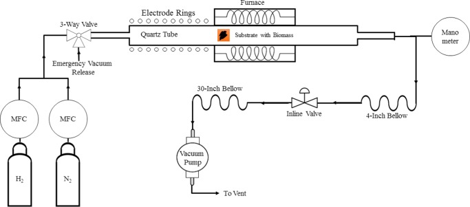
The mango peels (M. indica, L.), type Kent, were supplied by the frozen food producer Frexport, S.A. de C.V., Altex group, located at Zamora, Michoacan, Mexico. The biomass was dried at 60 °C for 72 h, ground up, and sieved using a mesh no. 18, which leads to a particle size of ≈1 mm. This is to obtain homogeneous powder samples. The synthesis of graphene was performed as follows: 10 mg of mango biomass was distributed homogeneously on a Cu substrate previously rinsed with ethanol and wiped. The substrate then was placed inside the reactor chamber, which was then pumped to vacuum. The samples were heated to 750 °C at a ramp of 25 °C min–1. A flow of 50 sccm of a mixture of 10% H2/Ar was employed. The samples were kept at 750 °C for 15 min, followed by a plasma exposure for 5, 15, 30, and 60 min, respectively, at 300 W plasma power. The samples were then cooled to room temperature at a natural cooling rate. The experiments were performed in an inhouse-built plasma reactor (Figure 7). The typical reaction pressure was 0.2 torr.
Figure 7.
Inhouse-built plasma reactor system employed for graphene growth.
Supporting Information Available
The Supporting Information is available free of charge on the ACS Publications website at DOI: 10.1021/acsomega.7b01825.
Thermogravimetric analysis (TGA) of commercial cellulose (Figure S1), biomass synthesis from mango peel, attenuated total reflection–Fourier transform infrared spectrum of pectin: commercial and mango peels (Figure S2) (PDF)
Author Contributions
The manuscript was written through contributions of all authors. All authors have given approval to the final version of the manuscript.
M.L.C. acknowledges the University of Tulsa faculty start up for financial support of this work.
The authors declare no competing financial interest.
Supplementary Material
References
- Edwards M. C.; Doran-Peterson J. Pectin-rich biomass as feedstock for fuel ethanol production. Appl. Microbiol. Biotechnol. 2012, 95, 565–575. 10.1007/s00253-012-4173-2. [DOI] [PMC free article] [PubMed] [Google Scholar]
- Grohmann K.; Bothast R.. Pectin-Rich Residues Generated by Processing of Citrus Fruits, Apples, and Sugar Beets. In Enzymatic Hydrolysis and Biological Conversion to Value-Added Products; ACS Symposium Series; American Chemical Society, 1994; Vol. 566, pp 372–390. [Google Scholar]
- Kermani Z. J.; Shpigelman A.; Pham H. T. T.; Van Loey A. M.; Hendrickx M. E. Functional properties of citric acid extracted mango peel pectin as related to its chemical structure. Food Hydrocolloids 2015, 44, 424–434. 10.1016/j.foodhyd.2014.10.018. [DOI] [Google Scholar]
- Sudhakar D.; Maini S. Isolation and characterization of mango peel pectins. J. Food Process. Preserv. 2000, 24, 209–227. 10.1111/j.1745-4549.2000.tb00414.x. [DOI] [Google Scholar]
- Banerjee J.; Vijayaraghavan R.; Arora A.; MacFarlane D. R.; Patti A. F. Lemon Juice Based Extraction of Pectin from Mango Peels: Waste to Wealth by Sustainable Approaches. ACS Sustainable Chem. Eng. 2016, 4, 5915–5920. 10.1021/acssuschemeng.6b01342. [DOI] [Google Scholar]
- Sogi D. S.; Siddiq M.; Greiby I.; Dolan K. D. Total phenolics, antioxidant activity, and functional properties of ‘Tommy Atkins’ mango peel and kernel as affected by drying methods. Food Chem. 2013, 141, 2649–2655. 10.1016/j.foodchem.2013.05.053. [DOI] [PubMed] [Google Scholar]
- Jahurul M. H. A.; Zaidul I.; Ghafoor K.; Al-Juhaimi F. Y.; Nyam K.-L.; Norulaini N.; Sahena F.; Omar A. M. Mango (Mangifera indica L.) by-products and their valuable components: A review. Food Chem. 2015, 183, 173–180. 10.1016/j.foodchem.2015.03.046. [DOI] [PubMed] [Google Scholar]
- Berardini N.; Knödler M.; Schieber A.; Carle R. Utilization of mango peels as a source of pectin and polyphenolics. Innovative Food Sci. Emerging Technol. 2005, 6, 442–452. 10.1016/j.ifset.2005.06.004. [DOI] [Google Scholar]
- Lemus C.; Bugarin J.; Bonilla J.; Ly J. Composition and chemical characteristics of mangoes (Mangifera indica L.) for animal feeding in Nayarit, Mexico. Cuban J. Agric. Sci. 2013, 47, 273–277. [Google Scholar]
- Bekyarova E.; Sarkar S.; Wang F.; Itkis M. E.; Kalinina I.; Tian X.; Haddon R. C. Effect of covalent chemistry on the electronic structure and properties of carbon nanotubes and graphene. Acc. Chem. Res. 2013, 46, 65–76. 10.1021/ar300177q. [DOI] [PubMed] [Google Scholar]
- Cooper D. R.; D’Anjou B.; Ghattamaneni N.; Harack B.; Hilke M.; Horth A.; Majlis N.; Massicotte M.; Vandsburger L.; Whiteway E.; et al. Experimental review of graphene. ISRN Condens. Matter Phys. 2012, 2012, 1–56. 10.5402/2012/501686. [DOI] [Google Scholar]
- Boukhvalov D.; Katsnelson M.; Lichtenstein A. Hydrogen on graphene: Electronic structure, total energy, structural distortions and magnetism from first-principles calculations. Phys. Rev. B 2008, 77, 035427 10.1103/PhysRevB.77.035427. [DOI] [Google Scholar]
- Yang J.-H.; Sun G.; Gao Y.; Zhao H.; Tang P.; Tan J.; Lu A.-H.; Ma D. Direct catalytic oxidation of benzene to phenol over metal-free graphene-based catalyst. Energy Environ. Sci. 2013, 6, 793–798. 10.1039/c3ee23623d. [DOI] [Google Scholar]
- Geng D.; Chen Y.; Chen Y.; Li Y.; Li R.; Sun X.; Ye S.; Knights S. High oxygen-reduction activity and durability of nitrogen-doped graphene. Energy Environ. Sci. 2011, 4, 760–764. 10.1039/c0ee00326c. [DOI] [Google Scholar]
- Park H. W.; Lee D. U.; Nazar L. F.; Chen Z. Oxygen reduction reaction using MnO2 nanotubes/nitrogen-doped exfoliated graphene hybrid catalyst for Li-O2 battery applications. J. Electrochem. Soc. 2013, 160, A344–A350. 10.1149/2.086302jes. [DOI] [Google Scholar]
- Yang X.; Yang Q.; Xu J.; Lee C.-S. Bimetallic PtPd nanoparticles on Nafion–graphene film as catalyst for ethanol electro-oxidation. J. Mater. Chem. 2012, 22, 8057–8062. 10.1039/c2jm16916a. [DOI] [Google Scholar]
- Yen M.-Y.; Teng C.-C.; Hsiao M.-C.; Liu P.-I.; Chuang W.-P.; Ma C.-C. M.; Hsieh C.-K.; Tsai M.-C.; Tsai C.-H. Platinum nanoparticles/graphene composite catalyst as a novel composite counter electrode for high performance dye-sensitized solar cells. J. Mater. Chem. 2011, 21, 12880–12888. 10.1039/c1jm11850a. [DOI] [Google Scholar]
- Hu H.; Xin J. H.; Hu H.; Wang X.; Kong Y. Metal-free graphene-based catalyst—Insight into the catalytic activity: A short review. Appl. Catal., A 2015, 492, 1–9. 10.1016/j.apcata.2014.11.041. [DOI] [Google Scholar]
- Wang H.; Xia B.; Yan Y.; Li N.; Wang J.-Y.; Wang X. Water-soluble polymer exfoliated graphene: as catalyst support and sensor. J. Phys. Chem. B 2013, 117, 5606–5613. 10.1021/jp401418z. [DOI] [PubMed] [Google Scholar]
- Ha T.-J.; Akinwande D.; Dodabalapur A. Hybrid graphene/organic semiconductor field-effect transistors. Appl. Phys. Lett. 2012, 101, 033309 10.1063/1.4737939. [DOI] [Google Scholar]
- Wu J.; Agrawal M.; Becerril H. A.; Bao Z.; Liu Z.; Chen Y.; Peumans P. Organic light-emitting diodes on solution-processed graphene transparent electrodes. ACS Nano 2010, 4, 43–48. 10.1021/nn900728d. [DOI] [PubMed] [Google Scholar]
- Agrawal R.; Chen C.; Hao Y.; Song Y.; Wang C.. Graphene for Supercapacitors. In Graphene-Based Energy Devices, 1st ed.; Wiley-VCH Verlag GmbH & Co. KGaA, 2015; pp 171–205. [Google Scholar]
- Xiang H.; Li Z.; Xie K.; Jiang J.; Chen J.; Lian P.; Wu J.; Yu Y.; Wang H. Graphene sheets as anode materials for Li-ion batteries: preparation, structure, electrochemical properties and mechanism for lithium storage. RSC Adv. 2012, 2, 6792–6799. 10.1039/c2ra20549a. [DOI] [Google Scholar]
- Ang P. K.; Chen W.; Wee A. T. S.; Loh K. P. Solution-gated epitaxial graphene as pH sensor. J. Am. Chem. Soc. 2008, 130, 14392–14393. 10.1021/ja805090z. [DOI] [PubMed] [Google Scholar]
- Zhao J.; Ren W.; Cheng H.-M. Graphene sponge for efficient and repeatable adsorption and desorption of water contaminations. J. Mater. Chem. 2012, 22, 20197–20202. 10.1039/c2jm34128j. [DOI] [Google Scholar]
- Stoller M. D.; Park S.; Zhu Y.; An J.; Ruoff R. S. Graphene-based ultracapacitors. Nano Lett. 2008, 8, 3498–3502. 10.1021/nl802558y. [DOI] [PubMed] [Google Scholar]
- Li X.; Cai W.; An J.; Kim S.; Nah J.; Yang D.; Piner R.; Velamakanni A.; Jung I.; Tutuc E.; et al. Large-area synthesis of high-quality and uniform graphene films on copper foils. Science 2009, 324, 1312–1314. 10.1126/science.1171245. [DOI] [PubMed] [Google Scholar]
- Yelgel C.; Srivastava G. Ab initio studies of electronic and optical properties of graphene and graphene–BN interface. Appl. Surf. Sci. 2012, 258, 8338–8342. 10.1016/j.apsusc.2012.03.167. [DOI] [Google Scholar]
- Tiwari A.; Singh Raman R. Durable Corrosion Resistance of Copper Due to Multi-Layer Graphene. Materials 2017, 10, 1112 10.3390/ma10101112. [DOI] [PMC free article] [PubMed] [Google Scholar]
- Nagashio K.; Nishimura T.; Kita K.; Toriumi A. Mobility variations in mono-and multi-layer graphene films. Appl. Phys. Express 2009, 2, 025003 10.1143/APEX.2.025003. [DOI] [Google Scholar]
- Ruan G.; Sun Z.; Peng Z.; Tour J. M. Growth of graphene from food, insects, and waste. ACS Nano 2011, 5, 7601–7607. 10.1021/nn202625c. [DOI] [PubMed] [Google Scholar]
- Boyd D. A.; Lin W.-H.; Hsu C.-C.; Teague M.; Chen C.-C.; Lo Y.-Y.; Chan W.-Y.; Su W.-B.; Cheng T.-C.; Chang C.-S.; et al. Single-step deposition of high-mobility graphene at reduced temperatures. Nat. Commun. 2015, 6, 6620 10.1038/ncomms7620. [DOI] [PubMed] [Google Scholar]
- Wang S.; Gong Q.; Li Y.; Cao C.; Zhou H.; Yan J.; Liu Q.; Zhang L.; Ding G.; Di Z.; et al. A novel semiconductor compatible path for nano-graphene synthesis using CBr4 precursor and Ga catalyst. Sci. Rep. 2014, 4, 4653 10.1038/srep04653. [DOI] [PMC free article] [PubMed] [Google Scholar]
- Carreon M. L.; Jasinski J.; Sunkara M. Low temperature synthesis of silicon nanowire arrays. Mater. Res. Express 2014, 1, 045006 10.1088/2053-1591/1/4/045006. [DOI] [Google Scholar]
- Cardillo M.; Balooch M.; Stickney R. Detailed balancing and quasi-equilibrium in the adsorption of hydrogen on copper. Surf. Sci. 1975, 50, 263–278. 10.1016/0039-6028(75)90024-2. [DOI] [Google Scholar]
- Malesevic A.; Vitchev R.; Schouteden K.; Volodin A.; Zhang L.; Van Tendeloo G.; Vanhulsel A.; Van Haesendonck C. Synthesis of few-layer graphene via microwave plasma-enhanced chemical vapour deposition. Nanotechnology 2008, 19, 305604 10.1088/0957-4484/19/30/305604. [DOI] [PubMed] [Google Scholar]
- Dato A.; Radmilovic V.; Lee Z.; Phillips J.; Frenklach M. Substrate-free gas-phase synthesis of graphene sheets. Nano Lett. 2008, 8, 2012–2016. 10.1021/nl8011566. [DOI] [PubMed] [Google Scholar]
- Tatarova E.; Henriques J.; Luhrs C.; Dias A.; Phillips J.; Abrashev M.; Ferreira C. Microwave plasma based single step method for free standing graphene synthesis at atmospheric conditions. Appl. Phys. Lett. 2013, 103, 134101 10.1063/1.4822178. [DOI] [Google Scholar]
- Kim Y.; Song W.; Lee S.; Jeon C.; Jung W.; Kim M.; Park C.-Y. Low-temperature synthesis of graphene on nickel foil by microwave plasma chemical vapor deposition. Appl. Phys. Lett. 2011, 98, 263106 10.1063/1.3605560. [DOI] [PMC free article] [PubMed] [Google Scholar]
- Kim Y.; Ishihara M.; Koga Y.; Tsugawa K.; Hasegawa M.; Iijima S. Low-temperature synthesis of large-area graphene-based transparent conductive films using surface wave plasma chemical vapor deposition. Appl. Phys. Lett. 2011, 98, 263106 10.1063/1.3605560. [DOI] [PMC free article] [PubMed] [Google Scholar]
- Yamada T.; Kim J.; Ishihara M.; Hasegawa M. Low-temperature graphene synthesis using microwave plasma CVD. J. Phys. D: Appl. Phys. 2013, 46, 063001 10.1088/0022-3727/46/6/063001. [DOI] [Google Scholar]
- Vitchev R.; Malesevic A.; Petrov R. H.; Kemps R.; Mertens M.; Vanhulsel A.; Van Haesendonck C. Initial stages of few-layer graphene growth by microwave plasma-enhanced chemical vapour deposition. Nanotechnology 2010, 21, 095602 10.1088/0957-4484/21/9/095602. [DOI] [PubMed] [Google Scholar]
- Kato R.; Tsugawa K.; Okigawa Y.; Ishihara M.; Yamada T.; Hasegawa M. Bilayer graphene synthesis by plasma treatment of copper foils without using a carbon-containing gas. Carbon 2014, 77, 823–828. 10.1016/j.carbon.2014.05.087. [DOI] [Google Scholar]
- Zhao R.; Ahktar M.; Alruqi A.; Dharmasena R.; Jasinski J. B.; Thantirige R. M.; Sumanasekera G. U. Electrical transport properties of graphene nanowalls grown at low temperature using plasma enhanced chemical vapor deposition. Mater. Res. Express 2017, 4, 055007 10.1088/2053-1591/aa6ee1. [DOI] [Google Scholar]
- Wang S.; Pei Y.; Wang X.; Wang H.; Meng Q.; Tian H.; Zheng X.; Zheng W.; Liu Y. Synthesis of graphene on a polycrystalline Co film by radio-frequency plasma-enhanced chemical vapour deposition. J. Phys. D: Appl. Phys. 2010, 43, 455402 10.1088/0022-3727/43/45/455402. [DOI] [Google Scholar]
- Qi J.; Zheng W.; Zheng X.; Wang X.; Tian H. Relatively low temperature synthesis of graphene by radio frequency plasma enhanced chemical vapor deposition. Appl. Surf. Sci. 2011, 257, 6531–6534. 10.1016/j.apsusc.2011.02.069. [DOI] [Google Scholar]
- Nang L. V.; Kim E.-T. Controllable synthesis of high-quality graphene using inductively-coupled plasma chemical vapor deposition. J. Electrochem. Soc. 2012, 159, K93–K96. 10.1149/2.082204jes. [DOI] [Google Scholar]
- Terasawa T.-o.; Saiki K. Growth of graphene on Cu by plasma enhanced chemical vapor deposition. Carbon 2012, 50, 869–874. 10.1016/j.carbon.2011.09.047. [DOI] [Google Scholar]
- Sharma S.; Kalita G.; Hirano R.; Shinde S. M.; Papon R.; Ohtani H.; Tanemura M. Synthesis of graphene crystals from solid waste plastic by chemical vapor deposition. Carbon 2014, 72, 66–73. 10.1016/j.carbon.2014.01.051. [DOI] [Google Scholar]
- Rosmi M. S.; Shinde S. M.; Rahman N. D. A.; Thangaraja A.; Sharma S.; Sharma K. P.; Yaakob Y.; Vishwakarma R. K.; Bakar S. A.; Kalita G.; et al. Synthesis of uniform monolayer graphene on re-solidified copper from waste chicken fat by low pressure chemical vapor deposition. Mater. Res. Bull. 2016, 83, 573–580. 10.1016/j.materresbull.2016.07.010. [DOI] [Google Scholar]
- Muramatsu H.; Kim Y. A.; Yang K. S.; Cruz-Silva R.; Toda I.; Yamada T.; Terrones M.; Endo M.; Hayashi T.; Saitoh H. Rice Husk-Derived Graphene with Nano-Sized Domains and Clean Edges. Small 2014, 10, 2766–2770. 10.1002/smll.201400017. [DOI] [PubMed] [Google Scholar]
- Singh P.; Bahadur J.; Pal K. One-Step One Chemical Synthesis Process of Graphene from Rice Husk for Energy Storage Applications. Graphene 2017, 6, 61–71. 10.4236/graphene.2017.63005. [DOI] [Google Scholar]
- Kumawat M. K.; Thakur M.; Gurung R. B.; Srivastava R. Graphene Quantum Dots from Mangifera indica: Application in Near-Infrared Bioimaging and Intracellular Nanothermometry. ACS Sustainable Chem. Eng. 2017, 5, 1382–1391. 10.1021/acssuschemeng.6b01893. [DOI] [Google Scholar]
- Gómez-Siurana A.; Marcilla A.; Beltrán M.; Berenguer D.; Martínez-Castellanos I.; Menargues S. TGA/FTIR study of tobacco and glycerol–tobacco mixtures. Thermochim. Acta 2013, 573, 146–157. 10.1016/j.tca.2013.09.007. [DOI] [Google Scholar]
- Burhenne L.; Messmer J.; Aicher T.; Laborie M.-P. The effect of the biomass components lignin, cellulose and hemicellulose on TGA and fixed bed pyrolysis. J. Anal. Appl. Pyrolysis 2013, 101, 177–184. 10.1016/j.jaap.2013.01.012. [DOI] [Google Scholar]
- Giudicianni P.; Cardone G.; Ragucci R. Cellulose, hemicellulose and lignin slow steam pyrolysis: Thermal decomposition of biomass components mixtures. J. Anal. Appl. Pyrolysis 2013, 100, 213–222. 10.1016/j.jaap.2012.12.026. [DOI] [Google Scholar]
- Werner K.; Pommer L.; Broström M. Thermal decomposition of hemicelluloses. J. Anal. Appl. Pyrolysis 2014, 110, 130–137. 10.1016/j.jaap.2014.08.013. [DOI] [Google Scholar]
- Dresselhaus M. S.; Jorio A.; Hofmann M.; Dresselhaus G.; Saito R. Perspectives on carbon nanotubes and graphene Raman spectroscopy. Nano Lett. 2010, 10, 751–758. 10.1021/nl904286r. [DOI] [PubMed] [Google Scholar]
- Michelsen H.; Auerbach D. A critical examination of data on the dissociative adsorption and associative desorption of hydrogen at copper surfaces. J. Chem. Phys. 1991, 94, 7502–7520. 10.1063/1.460182. [DOI] [Google Scholar]
- Michelsen H.; Rettner C.; Auerbach D.. The adsorption of Hydrogen at Copper Surfaces: a Model System for the Study of Activated Adsorption. In Surface Reactions; Springer, 1994; pp 185–237. [Google Scholar]
- Balooch M.; Cardillo M.; Miller D.; Stickney R. Molecular beam study of the apparent activation barrier associated with adsorption and desorption of hydrogen on copper. Surf. Sci. 1974, 46, 358–392. 10.1016/0039-6028(74)90315-X. [DOI] [Google Scholar]
- Anger G.; Winkler A.; Rendulic K. Adsorption and desorption kinetics in the systems H2/Cu (111), H2/Cu (110) and H2/Cu (100). Surf. Sci. 1989, 220, 1–17. 10.1016/0039-6028(89)90459-7. [DOI] [Google Scholar]
- Casiraghi C.Raman Spectroscopy of Graphene. In Spectroscopic Properties of Inorganic and Organometallic Compounds: Techniques, Materials and Applications; Royal Society of Chemistry, 2012; Vol. 43, pp 29–56. [Google Scholar]
- Malard L.; Pimenta M.; Dresselhaus G.; Dresselhaus M. Raman spectroscopy in graphene. Phys. Rep. 2009, 473, 51–87. 10.1016/j.physrep.2009.02.003. [DOI] [Google Scholar]
- Ferrari A. C. Raman spectroscopy of graphene and graphite: disorder, electron–phonon coupling, doping and nonadiabatic effects. Solid State Commun. 2007, 143, 47–57. 10.1016/j.ssc.2007.03.052. [DOI] [Google Scholar]
- Ferrari A. C.; Meyer J.; Scardaci V.; Casiraghi C.; Lazzeri M.; Mauri F.; Piscanec S.; Jiang D.; Novoselov K.; Roth S.; et al. Raman spectrum of graphene and graphene layers. Phys. Rev. Lett. 2006, 97, 187401 10.1103/PhysRevLett.97.187401. [DOI] [PubMed] [Google Scholar]
- O’kane D.; Mittal K. Plasma cleaning of metal surfaces. J. Vac. Sci. Technol. 1974, 11, 567–569. 10.1116/1.1318069. [DOI] [Google Scholar]
- Mostaghimi J.; Proulx P.; Boulos M. I. A two-temperature model of the inductively coupled rf plasma. J. Appl. Phys. 1987, 61, 1753–1760. 10.1063/1.338073. [DOI] [Google Scholar]
- Kornblum G.; De Galan L. Spatial distribution of the temperature and the number densities of electrons and atomic and ionic species in an inductively coupled RF argon plasma. Spectrochim. Acta, Part B 1977, 32, 71–96. 10.1016/0584-8547(77)80011-6. [DOI] [Google Scholar]
- Hopwood J.; Guarnieri C.; Whitehair S.; Cuomo J. Langmuir probe measurements of a radio frequency induction plasma. J. Vac. Sci. Technol., A 1993, 11, 152–156. 10.1116/1.578282. [DOI] [Google Scholar]
- Mattevi C.; Kim H.; Chhowalla M. A review of chemical vapour deposition of graphene on copper. J. Mater. Chem. 2011, 21, 3324–3334. 10.1039/C0JM02126A. [DOI] [Google Scholar]
- Collard F.-X.; Blin J. A review on pyrolysis of biomass constituents: Mechanisms and composition of the products obtained from the conversion of cellulose, hemicelluloses and lignin. Renewable Sustainable Energy Rev. 2014, 38, 594–608. 10.1016/j.rser.2014.06.013. [DOI] [Google Scholar]
- Goswami S.; Banerjee P.; Datta S.; Mukhopadhayay A.; Das P. Graphene oxide nanoplatelets synthesized with carbonized agro-waste biomass as green precursor and its application for the treatment of dye rich wastewater. Process Saf. Environ. Prot. 2017, 106, 163–172. 10.1016/j.psep.2017.01.003. [DOI] [Google Scholar]
Associated Data
This section collects any data citations, data availability statements, or supplementary materials included in this article.


