

Abstract
Fiber-optic endomicroscopy is a minimally invasive tool to image cellular structure with high resolution. In this study, we demonstrate a low-cost and compact fluorescence microendoscope capable of line-scanning confocal imaging by synchronizing a digital light projector with a CMOS camera. We present the digital aperture design to enable real-time confocal imaging, and we implement parallel illumination to improve the optical sectioning performance. Furthermore, we show that the confocal microendoscope can enhance visualization of disease-associated features when imaging highly scattering esophageal specimens.
Confocal endomicroscopy offers clinicians a powerful tool to visualize cellular architecture of highly scattering tissue with optical sectioning. For real-time biomedical applications, slit apertures are usually employed to achieve faster frame rates than point apertures. To implement slit apertures, a variety of mechanical scanning or spectral dispersion techniques have been used, such as polygon scanners, galvanometer mirrors, optoacoustic scanners, and diffraction gratings. [1–3] Recent advances in digital micromirror devices (DMD) technology make it practical to use an affordable digital light projector (DLP) as a versatile spatial light modulator and to digitally encode illumination sequences. Slit apertures on the DLP can be further programmed to spatiotemporally match the rolling shutter of a CMOS sensor and achieve confocal imaging without mechanical scanning. [4] Since both illumination and detection apertures on the DLP and CMOS can be digitally implemented, the cost and complexity of confocal alignment and scanning are reduced. [5] When compared with conventional physical scanners, these virtual apertures are accurate and versatile, but also have some constraints. For example, the number of patterns and their scanning rate are limited in an off-the-shelf DLP, which restricts imaging performance. In this study, we characterize the scanning capabilities of slit apertures using a commercial DLP and CMOS sensor, and we analyze the spatiotemporal barriers of synchronizing the two for real-time confocal imaging. We further demonstrate an aperture design to overcome these barriers and achieve real-time confocal imaging in a portable and low-cost high-resolution microendoscope (HRME). We also characterize the optical sectioning capability and report performance for nuclear morphometry imaging of esophageal submucosal dissection (ESD) specimens.
A schematic of the confocal HRME is shown in Figure 1A. As described in further detail elsewhere, [5] the confocal HRME is a fluorescence microscope using a LightCrafter 4500 DLP (Texas Instruments) as the light source and a scientific CMOS sensor (Firefly MV USB 2.0, FLIR Integrated Imaging Solutions) for imaging. Line illumination from the DLP is scanned and relayed onto the tissue surface through a coherent imaging fiber bundle (FIGH-30–850N, Myriad Fiber Imaging; 790 μm circular field of view). Fluorescence signal collected by the fiber bundle is descanned with the CMOS sensor in rolling shutter mode. Optical magnifications are calculated to match the confocal aperture sizes, and a trigger from the CMOS sensor initiates the DLP sequence in a synchronized manner. Two right-angle mirrors are used for fine confocal alignment. Without complicated opto-mechanical components, the entire system is built in a portable enclosure at a low cost (10” × 14” × 3”, <$5,000).
Figure 1.
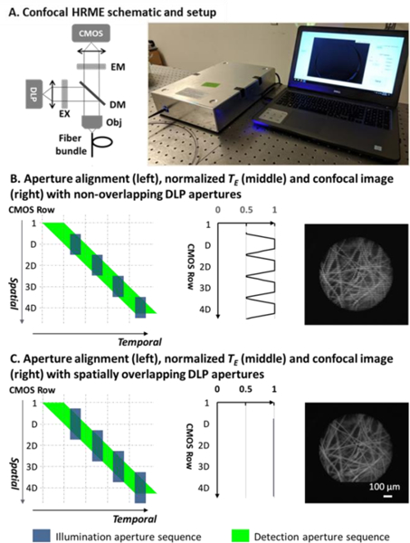
(A). Confocal HRME and its schematic. Confocal aperture alignment with non-overlapping (B) and spatially overlapping (C) DLP apertures. Imaging artifacts in (B) are eliminated with spatially overlapping DLP apertures in (C). EM: emission filter; EX: excitation filter; DM: dichroic mirror; Obj: objective.
The versatile programmability of the DLP and CMOS allows for accurate and repeatable control over the confocal slit apertures on a per frame basis. Unlike a conventional physical aperture that scans continuously, digital apertures in the confocal HRME are quantized, with a series of apertures scanned as binary patterns in a single frame acquisition. On one end, the illumination aperture is programmed as preloaded patterns in the DLP. With each pixel representing a micromirror in the DMD, the aperture size can be adjusted at the DMD pixel level. To scan the field of view (FOV), a sequence of binary patterns is projected by toggling the micromirrors on and off. On the other end, the detection slit aperture is achieved by adjusting the rolling shutter width. The exposure of CMOS rows is activated sequentially at a fixed row frequency fL. The number of rows under exposure concurrently Ddet, and hence the width of the rolling shutter aperture, is proportional to the shutter time Ts such that
| (1) |
The resulting detection aperture sequence, therefore, is also scanned at a row frequency fL; by adjusting the exposure time, the detection aperture size can be linearly tuned on a per CMOS pixel basis. In this study, the LightCrafter 4500 engine can project binary patterns of 1140 × 912 pixels at up to 2 kHz, and the CMOS rolling shutter scans across 1328 × 1048 pixels (1240 × 960 effective imaging pixels) at a fixed row frequency of 16.231 kHz.
While versatile and accurate, the two binary aperture sequences in the CMOS and DLP have distinctive spatiotemporal scanning characteristics, which makes confocal synchronization challenging. First, the illumination aperture speed is lower than that of the detection aperture. As previously mentioned, the detection aperture on the CMOS has a fixed line speed of about 16 kHz, and the illumination aperture can only be scanned at up to 2 kHz. In addition, the slower DLP sequence is projected in a discrete manner due to the discretized motion of the micromirrors; when operating at full speed, the DLP duty cycle can be as low as 50%. Second, the number of distinctive apertures supported by the DLP is considerably lower than that of the detection aperture. In a single frame acquisition, the rolling shutter scans over 960 CMOS rows, resulting in a sequence of 960 distinctive detection apertures. In contrast, the DLP flash memory supports storage of two 24-bit images, allowing only up to 48 illumination apertures to be projected at full speed. The disparity in the scanning rate and duty cycle, as well as the number of available binary patterns, make it impractical to synchronize the two aperture sequences on a per row basis, and thus pose challenges for real-time confocal imaging. First and foremost, as we have shown in our previous confocal HRME, the need for apertures covering multiple CMOS rows together with their scanning speed mismatch introduces illumination non-uniformity and thus makes confocal imaging vulnerable to motion artifacts in real time. [5] In addition, the relatively small number of DLP patterns limits the minimum width used to scan the FOV and thus restricts the confocal axial resolution. In this study, we redesign the DLP and CMOS aperture sequences to address both challenges.
The detailed scanning characteristics of two aperture sequences, as well as the aforementioned illumination non-uniformity, are illustrated in Figure 1B. Since the relative aperture size can be optically adjusted, both apertures will be described in CMOS rows. As shown by the green parallelogram in the left panel, the detection aperture sequence is scanned at a fixed row frequency fL, with the aperture size Ddet linearly determined by the CMOS shutter time. The DLP illumination aperture sequence, shown as blue rectangles, is designed to match the CMOS exposure. Spatially, we program the DLP illumination aperture size to match the rolling shutter aperture width Ddet]; using 48 available DLP patterns, adjacent illumination apertures are projected in a non-overlapping manner to illuminate the FOV with the smallest aperture. Temporally, in order to align two sequences, illumination apertures must be more sparsely distributed since they can only be projected with a duty cycle d at a slower scanning rate (Figure 1B, left panel). This spatiotemporal mismatch between two sequences contributes to a non-uniform distribution of the effective exposure time TE, defined as the temporal overlap between the illumination and detection apertures for each CMOS row along the scanning direction. Specifically, TE reaches a maximum at the center of illumination apertures and drops by half at their borders, resulting in confocal imaging artifacts (middle and right panels of Figure 1B). To better characterize the illumination artifacts, we calculate the number of under-illuminated rows on both sides of an illumination aperture Du:
| (2) |
in which TDLP is the illumination duration for each illumination aperture. It should be noted that when the aperture sequences are aligned, the illumination aperture period equals the shutter time Ts. Therefore, Equation 2 can also be written as:
| (3) |
in which d is the DLP aperture duty cycle. Equation 3 indicates that when using a spatially non-overlapping DLP sequence, a high duty cycle leads to more imaging non-uniformity even though it is desired to deliver more illumination.
In Figure 1C, we redesign the illumination apertures to enable real-time confocal imaging without illumination artifacts. Since the under-illuminated rows are only on the edge of illumination apertures, their TE loss can be compensated by spatially expanding the adjacent illumination apertures. More specifically, the illumination aperture width is increased by Du/2 on both ends so that these rows can be illuminated by two adjacent apertures. The resulting expanded illumination aperture width is
| (4) |
As shown in Figure 1C, the previously under-illuminated rows are illuminated by two adjacent DLP apertures in a complementary manner, ensuring that the total TE remains constant along the scanning direction. The resulting TE distribution is uniform (Figure 1C, middle panel), and confocal imaging without illumination artifacts (Figure 1C, right panel) can be achieved in real time.
In addition to enabling real-time confocal imaging, we also increased the axial resolution by parallelizing illumination apertures. As previously mentioned, in a single frame acquisition, the detection aperture sequence contains 960 distinctive apertures and the DLP only supports projection of 48 patterns at its full speed. As illustrated in the top panel of Figure 2A, to cover 960 CMOS rows with 48 patterns, the distance between illumination aperture centers should be no fewer than 20 pixels, which restricts the axial resolution. To overcome the aperture width limit imposed by the DLP storage capacity, we program parallel illumination apertures in DLP patterns. In the bottom panel of Figure 2A, each DLP pattern is redesigned to contain two apertures separated by 480 rows, with their width reduced by half; as a sequence of 48 patterns are scanned, the top and bottom half of the FOV are illuminated with two distinct apertures simultaneously. To align two aperture sequences, the detection aperture size is reduced accordingly, and the 48-pattern illumination sequence is projected repeatedly. Although the detection aperture cannot be parallelized, the high scanning linearity of two sequences ensures spatiotemporal alignment for confocal imaging.
Figure 2.

Confocal alignment without and with parallel illumination (A), and the resulting axial responses (B).
The resulting improvement in axial resolution was characterized by imaging a mirror in reflection mode. In Figure 2B, the non-confocal HRME shows minimal optical sectioning under wide-field illumination. For confocal imaging, 48 and 96 illumination apertures were scanned during a single frame acquisition in non-parallel and parallel scanning, respectively; the resulting rolling shutter aperture widths were 20.4 and 10.2 μm. In both configurations, the background rejection was significantly improved. Signal intensity dropped by half between 80 and 90 μm without parallel illumination, suggesting a FWHM of about 170 μm; with parallel illumination, the FWHM was further reduced to 100 μm. The results also suggest that parallelized illumination apertures on the same DLP pattern are adequately separated to minimize potential crosstalk.
We validated the performance of the real-time confocal HRME with parallel illumination by imaging esophageal submucosal dissection specimens that were topically stained with proflavine (0.01% w/v in PBS). The study was approved by the IRBs at Baylor College of Medicine and Rice University. The same FOVs were imaged using the non-confocal and confocal HRME. Sites were inked post-imaging for histopathological examination.
Figure 3 shows HRME images from an ESD specimen. Images of site A reveal a transitional region between columnar epithelium (glandular structure at 11 to 7 o’clock) and squamous epithelium (nuclear structure at 7 to 11 o’clock). Confocal imaging enhances visualization of both types of epithelium. The optical sectioning was further quantified along two linescans in the squamous and columnar epithelial regions (solid and dashed lines on top panel, respectively). As shown in the intensity profile, individual nuclei indicated by black arrows are clearly resolved in the confocal image, while their contrast can be poor in the non-confocal image. Similarly, background signal in the lumens is significantly reduced in the confocal HRME, resulting in sharpened glandular borders.
Figure 3.

Images acquired with the non-confocal and confocal HRME of an ESD specimen. Intensity profiles (solid lines: nuclei; dashed line: glands; dotted line: microvessels) are shown to quantify the background rejection in confocal HRME. Circular FOV: 790 μm
Images of site B in Figure 3 show nuclear crowding together with increased microvasculature. Two linescans are quantified in the nuclear crowding region and the vascular region (solid and dotted lines on top panel, respectively). The nuclear profile of site B shows clearly delineated nuclei (black arrows) in the confocal intensity profile, even though scattering background is higher due to nuclear crowding. For microvascular imaging, the confocal image also shows improved background rejection with enhanced contrast.
We also assessed optical imaging features associated with esophageal cancer progression using the non-confocal and confocal HRME. Figure 4 shows representative images of sites diagnosed as normal Barrett’s esophagus (BE), high grade dysplasia (HGD) and esophageal adenocarcinoma (EAC). In benign BE, the glandular patterns appear regular and intact. Progressing to HGD and EAC, the glandular patterns become disrupted and effaced, accompanied by nuclear enlargement and crowding. These features are also evident in the accompanying histopathology images. When compared with non-confocal HRME images, confocal images showed enhanced contrast of both glandular patterns and individual nuclei. In the confocal image of BE, background signal in the lumens is significantly reduced; the glandular walls are also delineated with sharper edges. Individual nuclei (black arrows) on the HGD glands can be readily discerned in the confocal image, while the contrast is relatively lower in the non-confocal HRME; similarly, the nuclear crowding in EAC can be visualized with enhanced contrast in confocal HRME, as confirmed by the line profiles.
Figure 4.

Representative images acquired with the non-confocal and confocal HRME. Intensity profiles along the line scans (white dotted lines) are shown to quantify the optical sectioning. BE: Barrett’s esophagus; HGD: high grade dysplasia; EAC: esophageal adenocarcinoma. Circular FOV: 790 μm.
Ex vivo imaging demonstrates that the confocal HRME can better resolve clinically relevant features associated with disease progression, including individual nuclei, glands, and microvasculature. The confocal system described here differs from a conventional confocal microscope in several aspects. First, we implemented two digital apertures with distinctive scanning characteristics to perform confocal line-scanning, while conventional confocal systems usually employ the same type of apertures to scan and descan the FOV. Second, the digital nature of the two apertures allows for rapid and accurate control over the system. In addition, without the need for complicated opto-mechanical systems, the device can be built in a small enclosure at a low cost.
In conclusion, we demonstrate the implementation of real-time line-scanning confocal imaging using an affordable off-the-shelf DLP and a CMOS camera. We further integrate them to build a low-cost high-resolution microendoscope (<$5000) and show that its optical sectioning capability can enhance the visualization of disease-associated alterations in cellular architecture. The system can be adapted for other novel optical configurations, and future work is warranted to explore the potential benefits of optical sectioning when imaging a variety of pathological conditions.
Acknowledgment.
We thank Madeleine Allman for coordinating patient accrual. We also appreciate assistance from Drs. Nadeem Dhanani and Richard Schwarz.
Funding. Dan L. Duncan Cancer Center (DLDCC) Pilot Project Grant; National Cancer Institute (NCI) (R01CA103830); National Science Foundation (NSF) (1730574)
Full references
- 1.Im K-B, Han S, Park H, Kim D, and Kim B-M, “Simple high-speed confocal line-scanning microscope,” Opt. Express 13, 5151–5156 (2005). [DOI] [PubMed] [Google Scholar]
- 2.Tearney GJ, Webb RH, and Bouma BE, “Spectrally encoded confocal microscopy,” Opt. Lett. 23, 1152 (1998). [DOI] [PubMed] [Google Scholar]
- 3.Sabharwal YS, Rouse AR, Donaldson L, Hopkins MF, and Gmitro AF, “Slit-scanning confocal microendoscope for high-resolution in vivo imaging.,” Appl. Opt. 38, 7133–7144 (1999). [DOI] [PubMed] [Google Scholar]
- 4.Muller MS, Green JJ, Baskaran K, Ingling AW, Clendenon JL, Gast TJ, and Elsner AE, “Non-mydriatic confocal retinal imaging using a digital light projector,” Proc. SPIE--the Int. Soc. Opt. Eng. 9376, 93760E (2015). [DOI] [PMC free article] [PubMed] [Google Scholar]
- 5.Tang Y, Carns J, and Richards-Kortum RR, “Line-scanning confocal microendoscope for nuclear morphometry imaging.,” J. Biomed. Opt. 22, 1–6 (2017). [DOI] [PMC free article] [PubMed] [Google Scholar]