Abstract
MoS2 is a 2D material that has been widely used in supercapacitor applications because of its layered structure that provides a large surface area and allows for high electric double-layer charge storage. To enhance the cycling stability and capacitance of MoS2, it is usually mixed with carbon materials. However, the dependence of the charge storage mechanism on the structure of the carbon material is still unclear in literature. Herein, the effect of the structure of the carbon material on the charge storage mechanism in 2H flower-shaped MoS2 is investigated in detail. Specifically, 2H MoS2 was mixed with either 8 nm-diameter carbon nanotubes (CNTs) or graphene nanoflakes (GNFs) in different weight ratios. Also, a composite of MoS2, CNTs, and GNFs (1:1:1) was also studied. The charge storage mechanism was found to depend on the structure and content of the carbon material. Insights into the possible storage mechanism(s) were discussed. The MoS2/CNT/GNF composite showed a predominant pseudocapacitive charge storage mechanism where the diffusion current was ∼89%, with 88.31% of the resulted capacitance being due to faradic processes.
Introduction
Supercapacitors (SCs) have attracted much attention as the next-generation power storage devices, mainly because of their outstanding cycling life, safe operation, and higher power density than fuel cells and batteries.1−3 However, the bottleneck preventing their large-scale production and utilization is their comparatively low energy density.4 In this regard, pseudocapacitive materials, such as metal oxides and metal sulfides, have primarily been used in SC devices because of their high capacitance compared to carbonaceous materials.5,6 Whereas pseudocapacitive materials store charges via rapid and reversible faradaic reactions at the electrode surface, capable of storing higher energy, carbonaceous materials store energy physically via the formation of the electric double layer (EDL) with lower energy storage but higher cycle life stability.5,7−12 In this regard, layered materials, such as MoS2, have the ability to intercalate with ions in the electrolyte through a faradic process (diffusion), acting as a pseudocapacitor. Unfortunately, pseudocapacitors have a limitation of losing stability over time.13 To overcome the drawbacks of the two types of materials, researchers are using hybrid electrodes of both carbon and MoS2 together. Understanding the charge storage mechanism is the primary step to enhance the capacitance performance of the material.14−16
Among the various materials studied, two-dimensional metal dichalcogenides have been investigated as promising candidates for SCs.17,18 Specifically, molybdenum disulfide (MoS2) has recently been investigated for the applications in charge storage because of its graphene-like layered structure and the possibility to uphold faradic process reactions.19−23 MoS2 consists of two sheets of S sandwiching a sheet of Mo and the layers are connected together through van der Waal’s forces. This structure results in a high surface area and allows the intercalation of the ionic species from the electrolyte without high distortion of the crystal structure, providing a pseudocapacitive charge transfer character.17,24 MoS2 has three main phases; the 3R and the 2H phases are semiconductors, and the 1T phase has metallic properties.25,26 Whereas the 1T phase has a higher conductivity and capacitance, the 2H phase is more structurally stable.4,25,27,28 The 2H MoS2 has a low conductivity and low cycling stability, which affect its capacitance performance. In order to increase the capacitance of MoS2, it is usually mixed with carbon materials.29−31
Although a plethora of studies have focused on the performance of carbon/MoS2 composites, the effect of the shape and amount of the carbon material on the charge storage mechanism is yet to be explored. Herein, the charge storage mechanism in 2H MoS2 with and without carbon additives was explored in detail. The 2H MoS2 was mixed with different proportions of either 8 nm diameter carbon nanotubes (CNTs) or graphene nanoflakes (GNFs) and the effect of the structure and content of the carbon material on the charge storage performance and mechanism in MoS2 was explored in detail.
Results and Discussion
Characterization of the As-Fabricated MoS2 and the Composites
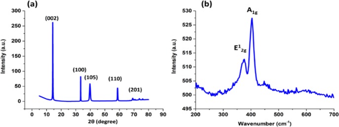
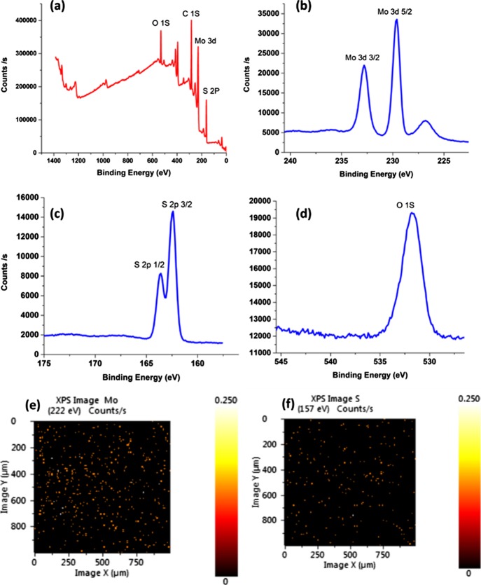
Figure 1a shows the X-ray diffraction pattern of the as-fabricated MoS2, revealing diffraction peaks at 2θ of 14.25°, 33.3°, 39.7°, 58.68°, and 69°, which can be attributed to the (002), (100), (105), (110), and (201) planes, respectively. This indicates the 2H hexagonal structure of the as-fabricated MoS2 (JCPDS 37-1492).32 The high intensity of the (002) peak reveals a well-crystalline layered structure along the c-axis with a calculated interlayer spacing of 0.62 nm, which is the ideal spacing in the MoS2 hexagonal crystals.32,33 To further investigate the crystal structure of the MoS2, Raman spectroscopy was performed as shown in Figure 1b. The Raman spectra showed two main peaks at 376 and 404 cm–1, corresponding to the in-plane E2g1 vibration and the vertical plane A1g vibration that occur in the Mo–S bond of the hexagonal 2H-MoS2 phase, respectively.19,34 The composition and chemical states of the elements of the synthesized MoS2 were investigated using X-ray photoelectron spectroscopy (XPS). The XPS survey of MoS2 (Figure 2a) showed a predominance of the elements Mo, S, C, and O. The high-resolution spectra of the O 1s (Figure 2d) revealed a main peak at a binding energy of 531.8 eV, which can be attributed to adsorbed oxygen from air.35 The high-resolution spectra of Mo (Figure 2b) showed two peaks at binding energies of 232.8 and 229.6 eV corresponding to the Mo 3d3/2 and Mo 3d5/2, respectively, with a spin orbit splitting of 3.2 eV, indicating an Mo(IV) valence state.19 The high-resolution spectra of S (Figure 2c) showed two peaks at binding energies of 162.46 and 163.63 eV corresponding to the S 2p3/2 and S 2p1/2, respectively, with a spin orbit splitting of 1.17 eV, corresponding to the S2– valence state.19,36,37 Further investigation showed that the ratio between Mo and S in the sample was 1:2.28, which proves the enriched sulfur content in the sample. The XPS elemental mapping (Figure 2e,f) showed a uniform distribution of both Mo and S atoms in the synthesized MoS2.
Figure 1.
(a) X-ray diffraction pattern and (b) Raman spectra of MoS2.
Figure 2.
(a) XPS survey, HR-XPS spectra of (b) Mo 3d, (c) S 2p, (d) O 1s, XPS mapping of (e) Mo and (f) S.
The morphological structure of the fabricated MoS2 was investigated using high-resolution transmission electron microscopy (HR-TEM) as shown in Figure 3a,b. The HR-TEM images confirm the layered structure of the MoS2 and the lattice fingers were found to be 0.26 nm (Figure 3c), matching the d-spacing calculated from the XRD spectra. The selected area electron diffraction (SAED) patterns of the MoS2 showed clear rings representing the (002), (100), (105), and (110) planes of the hexagonal MoS2 structure (Figure 3c).
Figure 3.
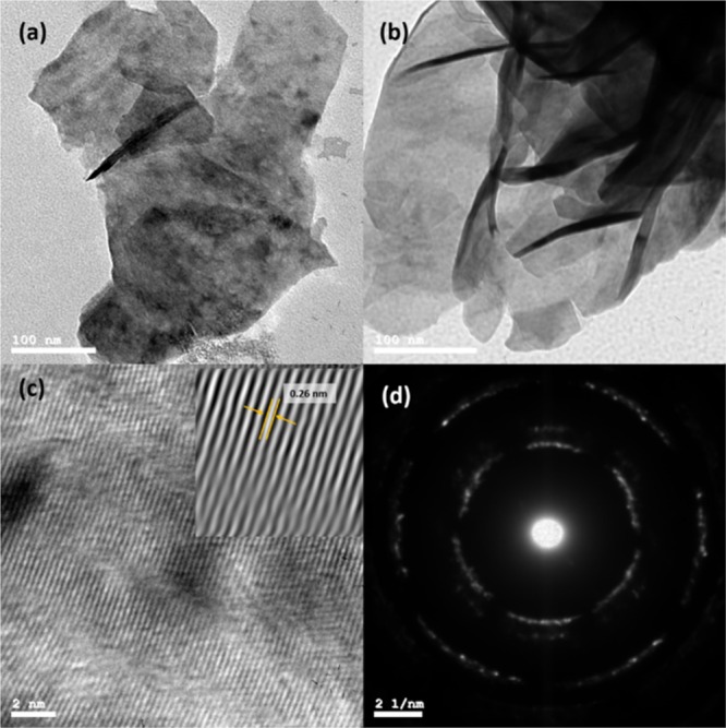
(a,b) TEM images, (c) HR-TEM image, and (d) SAED patterns of the as-fabricated MoS2.
The morphology of MoS2/CNTs and MoS2/GNF composites was investigated using field emission scanning electron microscopy (FESEM). Figure 4a reveals the flower-like structure of pure MoS2, with different flower sizes ranging from 1 to 5 μm. The FESEM image of the MoS2/CNTs composite (Figure 4b) shows the CNTs to be imbedded between the layers of the MoS2 flowers, which can be ascribed to the very small diameter (8 nm) of the used CNTs. With increasing the amount of the added CNTs, the MoS2 surface becomes almost completely covered with CNTs, Figure S1. For the MoS2/GNF composite (Figure 4c), the GNFs (1.0–2.5 μm) sandwiched the MoS2 flowers. Upon reducing the ratio of the added GNF, the MoS2 accumulated on the surface of the GNF and the flower shape started to deform and collapse into a ball-like shape as shown in Figure S1. For the MoS2/CNTs/GNF composite with equal weights (Figure 4d), both the MoS2 and the impeded CNTs were sandwiched into the GNF. The Brunauer–Emmett–Teller (BET) analysis of the active materials, Table S1, revealed a specific area of ∼7 m2/g for the pure MoS2, which is enormously increased with increasing the amount of CNTs to reach 180.6995 m2/g for the MCNT 1:3. On the contrary, the addition of GNF did not have a relatively significant effect on the surface area of the prepared MoS2/GNF composites. By measuring the contact angle for the composites, it was found that the added CNTs decreased wettability along with diffusion of ions inside the MoS2 flowers, whereas the GNFs increased the wettability along with the possibility of diffusion of ions into the MoS2 flower. The insets in Figure 4 show the contact angles for the composites MCG, MCNT 1:1, and MGNF 1:1.
Figure 4.
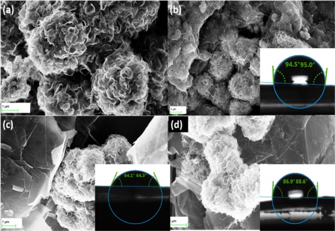
FESEM images of the studied materials: (a) MoS2, (b) MCNT 1:1, (c) MGNF 1:1, and (d) MCG 1:1:1. The insets show the corresponding contact angles.
Electrochemical Performance of the Studied Materials
Materials can store charges via two possible mechanisms. The first one is based on the faradic charge transfer mechanism, namely, “Pseudocapacitive”, during which the alkali metal cation from the electrolyte (here Na+) will diffuse between the layers of MoS2 and intercalate with it.32,34
| 1 |
The second charge storage mechanism is due to a non-faradic process in which the charges accumulate on the electrode/electrolyte interface, forming an electrical double layer. In this mechanism, the charge is stored on the surface or near it.
| 2 |
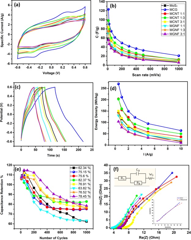
To investigate the electrochemical performance of the prepared composites as potential SC electrodes, the cyclic voltammetries (CVs) and charge/discharge characteristics were studied using a three-electrode system in 0.5 Na2SO4 electrolyte solution. Figure S2 shows the CVs of the studied materials at different scan rates (from 10 to 1000 mV/s). Note that all studied materials were able to maintain the semirectangular shape up to 500 mV/s. Figure 5a compares the CVs of the studied materials at a scan rate of 100 mV/s. Note that the more the added CNTs or GNF to the MoS2, the more ideal the rectangular shape appears, with the peaks starting to be more flattened. The ideal rectangular shape of the CV indicates the pure EDL capacitance charge storage mechanism, whereas the deviation from the rectangular shape indicates the faradic pseudocapacitive mechanism of the charge storage.7 The specific capacitance of the prepared materials was calculated from the CVs and is depicted in Figure 5b. At a scan rate of 10 mV/s, the specific capacitance of the pure MoS2 was 58.35 F/g and that of the MCG composite was 123.18 F/g. To investigate the origin of such increase in capacitance, the capacitance of MCNT and MGNF with different ratios was also calculated. The MCNT 1:3 showed a specific capacitance of 98.5 F/g, which was decreased to 90.3 and 83.77 F/g for MCNT 1:1 and MCNT 3:1, respectively. On the other hand, the MGNF 1:3 showed a specific capacitance of 74.68 F/g that was decreased to 69.98 and 55.33 F/g for MGNF 1:1 and MGNF 1:3, respectively. The results suggest that the CNTs may have the leading role in the increment of the charge stored in the MCG, which can be due to the large surface area of CNTs as estimated via the BET measurements. Although the calculated active surface area was larger for the CNT composites than for the MCG, the MCG specific capacitance was larger than that of the CNT composites. We believe the reason is that CNTs hinder the diffusion of ions into MoS2 layers. At scan rates higher than 10 mV/s, the capacitance of the MoS2/CNT composites kept the same trend, Figure 5b. On the contrary, the MoS2/GNF showed a reverse trend, where the MGNF 1:1 shows a higher capacitance than that of MGNF 1:3. The charge/discharge analysis showed a similar trend to the CV data. Figure S3 shows the charge/discharge plots of the prepared materials at different applied current densities (from 0.5 to 10 A/g). The selected charge/discharge plots for the prepared materials at 1 A/g are presented in Figure 5c, revealing ideal behavior of the pseudocapacitive charge storage mechanism. The pseudocapacitive behavior is believed to be due to the intercalation process between the MoS2 and the Na ions in the electrolyte as indicated by eq 1 above as MoS2 has empty orbitals that can intercalate with ions and the layered structure of the MoS2 allows the diffusion of ions in between the layers.
Figure 5.
(a) CV of the studied composites at 100 mV/s vs SCE, (b) Change of specific capacitance with scan rate for the studied materials, (c) charge/discharge curves for the studied materials at 1 A/g, (d) change of energy density of the studied materials, (e) retention of the studied materials; the mentioned percentage is after the 1000 cycle, (f) Nyquist plot for the studied materials in the frequency range of 10 kHz to 100 mHz.
However, the discharge line is more flattened for the 1:3 MGNF and MCNT, indicating that the charge storage mechanism is more directed toward the ideal EDL charge storage mechanism.7 The calculated capacitance from the discharge curve shows a similar trend to those calculated from the CV scans. The MoS2 specific capacitance was 56 F/g at 0.5 A/g and increased to 104 F/g for the MCG. Upon increasing the applied current density, the capacitance of MoS2 decreased, whereas that of MoS2/CNT composites showed the trend MCNT 1:3 > MCNT 1:1 > MCNT 3:1. Similar to those calculated from the CV scans, the MoS2/GNF composites showed a different trend such that at a low applied current density, the MGNF 1:3 showed the highest capacitance value between the three tested MoS2/GNF composites. However, upon increasing the applied current density, the MCNT 1:1 initially showed a higher capacitance then returned back to the normal trend at a very high applied current density (10 A/g). The energy density shows the same trend as the capacitance calculated from the discharge plots (Figure 5d) with the energy density of MoS2 at 0.5 A/g reaching 145.152 W h/kg, which increased to 269.892 W h/kg for the MCG. Figure 5e shows the plots of the capacitance retention over 1000 cycles of charge/discharge at 1 A/g current density. The Coulombic efficiency increased dramatically after the first 100 cycles and reached up to 95% after the first 500 cycles. The retention increased above 104% after the first 10 cycles and continued to increase until the 100th cycle because of the diffusion of ions in the pores of the materials and possible improvement of the wettability of the material over time.38 The retention started to decrease after the 200th cycle and stabilized between the 700th and the 800th cycle. The retention of the MoS2 after the 1000 cycle was 62.34% and increased to 82.37% for the MCNT 1:3. For the MCG, the retention reached 75.15% after the 1000 cycle with a capacitance of 61.32 F/g at 1 A/g.
Electrochemical impedance spectroscopy (EIS) is a good tool to elucidate the resistance of the working electrodes and investigate the working mechanisms. Figure 5f shows the Nyquist plots of the studied materials, revealing a small semicircle in the high-frequency regime and a tilted line in the low-frequency regime. The smaller the semicircle, the higher the conductivity of the material will be. The tilted line is due to the Warburg impedance resulted from the diffusion of Na+ ions into the MoS2 sheets.19 The effect of the intercalation in the MoS2 affected the ideal shape of the Nyquist plot.19 The Nyquist plot was fitted using the equivalent electrical circuit shown in Figure 5f, with the detailed fittings represented in the inset. R1 represents the resistance of the solution, R2 represents the surface resistance, and W represents the Warburg impedance. Note that, at a high frequency, the Warburg is small because of the low diffusion, whereas at a low frequency, the Warburg resistance increases because of the increase of the diffusion of ions into the materials.8Table S2 lists the fitting parameters, where R1 does not vary between the different materials. However, the Warburg impedance is lower for pure MoS2 and increases with increasing the amount of the added carbon material (CNTs or GNFs).
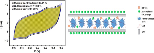
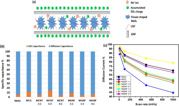
The in-depth understanding of the obtained results could be possible via the analysis of the contribution of both EDL charge storage and the diffusion intercalation charge storage to the obtained capacitance. Figure 6a shows a schematic representation of the MCG charge storage mechanism in which the small diameter (8 nm) CNTs are surrounding the MoS2 and the large GNFs are sandwiching the MoS2. This structure would result in maintaining both the large surface area (EDL capacitance) and allowing the diffusion of ions to intercalate within the layers of the MoS2. To this end, Tafel’s relation was used to estimate the EDL contribution. All tested materials resulted in b values (the intercept of the log i vs log v plot) that are ∼0.6, indicating the predominance of the diffusion charge storage mechanism.14,15 Moreover, using Trasatti’s method,16 the total capacitance (EDL and the diffusion) was calculated. It is worth mentioning that because of the used neutral electrolyte and the high scan rate, the relations were not entirely linear.16 Thus, the fitting was done in the low scan rate regime. Figure 6b shows a representation of the percentage EDL capacitance and the diffusion capacitance. It can be noticed that CNTs have the highest effect on increasing the EDL contribution in the capacitance performance, which can be related to their small size that favors the EDL mechanism. However, GNFs only surround the MoS2 layers and contribute their surface area to the original EDL of MoS2. From the BET analysis, it was found that the addition of GNFs did not increase the surface area that much; thus, GNFs did not show a significant change in the contribution of the EDL capacitance. In general, it was observed that the more contribution of EDL capacitance over the diffusion capacitance led to higher overall capacitance. The plot of v–1/2 versus i(v)/v1/2 was used to estimate the percentage of the diffusion current at different scan rates. Note that the linearity of the graph increases with increasing the amount of added carbon material, indicating a more ideal behavior and reduction in the Ohmic drop.15 The results (Figure 6c) showed that increasing the scan rate resulted in a decrease in the percentage of the diffusion current. Also, upon increasing the percentage of added carbon material, the percentage of the diffusion current is greatly reduced. However, at a lower sweep voltage, the contribution of the diffusion current is almost the same irrespective of the amount of added carbon material. The contribution of the diffusion current becomes significant at high sweep voltages, which can be ascribed to the possibility that, at a high sweep voltage, the ions can reach the interior of the CNTs and the GNFs, increasing the participation of the EDL capacitance in the charge storage mechanism.
Figure 6.
(a) Schematic diagram for possible charge storage in MCG, (b) percentage of EDL capacitance and diffusion capacitance estimated from Trasatti’s method, and (c) variation of diffusion current with scan rate.
Conclusions
We demonstrate the successful fabrication of 2H MoS2 and its composites with CNTs and GNFs. The capacitance of the fabricated composites was found to depend on the structure of the carbon material. The MoS2/CNT/GNF (1:1:1) composite showed a capacitance retention of 75% after the 1000 cycle at a scan rate of 10 mV/s. In-depth analysis of the origin of the charge storage mechanism was investigated. The analysis indicated that by increasing the content of the carbon material in the composite, the charge storage behavior is more directed toward the EDL charge storage mechanism. The added CNTs to MoS2 increased the capacitance, the EDL capacity, and reduced the percentage of diffusion current more than the added GNF counterpart. The positive effects of CNTs were ascribed to their small diameters and large surface area. Besides, CNTs enhanced the EDL contribution more than the diffusion counterpart. On the other hand, the GNFs only surrounded the MoS2 with limited surface area and without interference with the diffusion of the ions into the MoS2.
Experimental Section
Synthesis of Flower-Shaped MoS2
In a typical synthesis of MoS2 nanosheets, 2.47 g of (NH4)6Mo7O24·4H2O and 0.76 g of CS(NH2)2 are dissolved in 60 mL of distilled water (DW) under constant stirring. The mixture is transferred to a 150 mL Teflon-lined stainless-steel autoclave and preheated at 200 °C for 24 h. The black precipitate is collected by centrifugation, washed with DW and ethanol, and dried in an oven at 80 °C for 12 h. The produced powder is post-treated in a tube furnace (Carbolite) at 800 °C under Ar atmosphere for 2 h.
Preparation of the Studied Composites
The synthesized MoS2 was mixed with CNTs (Sigma) in the ratios of 1:1, 1:3, and 3:1 wt %, then sonicated in 100 mL of DW for 30 min, and finally dried overnight at 80 °C. The resulting composites are named as MCNT 1:1, MCNT 1:3, and MCNT 3:1, respectively. The MoS2 was also mixed with GNFs (Sigma) in the ratios 1:1, 1:3, and 3:1 wt %, then sonicated in 100 mL DW for 30 min, and finally dried overnight at 80 °C. The resulting composites are labeled MGNF 1:1, MGNF 1:3, and MGNF 3:1, respectively. Finally, the MoS2 was mixed with CNTs and GNFs in the ratio of 1:1:1 wt %, then sonicated in 100 mL DW, and dried overnight at 80 °C. The resulting composite is labeled MCG.
Characterization
The crystal structure and composition of the MoS2 were investigated using an X-ray powder diffractometer (Panalytical X’pert PRO MPD X-ray diffractometer) with Cu Kα radiation (λ = 0.15418 nm, 40 kV, 30 mA), and XPS (ESCALAB 250XI, Thermo Scientific), respectively. Raman spectroscopy was performed using a dispersive Raman microscope (Pro Raman-L Analyzer) with an excitation wavelength of 512 nm and laser power of 1 mW. HR-TEM (JOEL JEM-2100) was used for imaging and selected area diffraction analysis. The morphology and nanostructure of the studied samples were investigated using the FESEM (Zeiss SEM Ultra 60, 5 kV). The accelerated surface area and porosimetry were used for measuring the adsorption/desorption of the nitrogen isotherm at −196 °C; the BET plot with the nitrogen adsorption isotherm was used to indicate the specific surface area.
Electrochemical Measurements
The electrochemical measurements were performed using a three-electrode system. The working electrode was prepared as a slurry of 80% active material, 10% carbon black, and 10% polyvinylidene fluoride dissolved in dimethyl formamide on a substrate of (1 × 1 cm2) graphite sheet. A (1 × 1 cm2) Pt sheet was used as the counter electrode, a calomel electrode was used as the reference electrode, and 0.5 M Na2SO4 as the electrolyte. Electrochemical measurements were performed using a BioLogic SP-300 potentiostat. Cyclic voltammetry (CV) measurements were carried out at scan rates from 10 to 1000 mV s–1 in the potential window (−0.6 to 0.6 V). The galvanostatic charge/discharge (GCD) tests were carried out at different current densities (0.5, 1, 2, 3, 4, 5, and 10 mA g–1). The EIS was carried out in the frequency range of 10 kHz to 100 mHz.
Electrochemical Calculations
The specific capacitance can be calculated in F/g from the CVs through eq 3, where Cs is the specific capacitance, I is the response current density, v is the potential scan rate, ΔV is the potential window, and m is the mass of the electrode material.
| 3 |
The specific capacitance can also be calculated from the GCD graphs according to eq 4, where dt is the discharging time (s), I is the discharging current (A), m is the mass of the active material (g) within the electrode, and dV is the discharging potential range (V).
| 4 |
The power density, which is the strength point of the SC, can be calculated from eq 5, where E is the energy density and P is the power density.
| 5 |
In order to investigate the charge storage mechanism, the CV can be investigated using eq 6.14,39 By plotting log i versus log v, one can get the slope “b”, which relates the current to the charge transfer mechanism via Tafel’s equation and can have values of either b = 0.5 corresponding to faradic intercalation mechanism, or b = 1.0 corresponding to EDL capacitive mechanism.14,39 In this work, i is taken at V = 0 V.
| 6 |
Using eq 7,14,39 one can expect that current response at a fixed potential is a combination of two separate mechanisms, the capacitive resulting current (k1v) and the diffusion-controlled mechanism resulting current (k2v1/2), where k1 and k2 are obtained from the slope and intercept of the v–1/2 versus i(V)/v1/2 plot, respectively, where v is the scan rate in mV/s and i(v) is the current in mA “here taken at V = 0 V”. Solving the equation will give the contributions of current, either double-layer or diffusion-controlled, at a specific potential and specific scan rate.14,39
| 7 |
To further investigate the charge storage mechanism effect on the total capacitance, we used Trasatti’s method.16 This method assumes that at a scan rate of 0 mV/s, the charges are accessible to the surface and inner regions of the electrode, which corresponds to the total capacitance, whereas at a scan rate of ∞, the charges are only related to the outer surface and the related capacitance is due to the EDL capacitance mechanism. Thus, when plotting specific capacitance versus the inverse of the square root of the scan rate (mV/s), one can get the EDL capacitance and when plotting the inverse of the specific capacitance versus the square root of the scan rate (mV/s), one can get the total capacitance.14,40
Acknowledgments
Support of this work by the American University in Cairo is gratefully acknowledged. Basant Ali is supported by an Allehedan Endowed Scholarship.
Supporting Information Available
The Supporting Information is available free of charge on the ACS Publications website at DOI: 10.1021/acsomega.8b02261.
SEM images, BET analysis, CVs, and charge–discharge analysis (PDF)
The authors declare no competing financial interest.
Supplementary Material
References
- Hu B.; Qin X.; Asiri A. M.; Alamry K. A.; Al-Youbi A. O.; Sun X. Synthesis of Porous Tubular C/MoS2 nanocomposites and Their Application as a Novel Electrode Material for Supercapacitors with Excellent Cycling Stability. Electrochim. Acta 2013, 100, 24–28. 10.1016/j.electacta.2013.03.133. [DOI] [Google Scholar]
- Huang K.-J.; Wang L.; Liu Y.-J.; Wang H.-B.; Liu Y.-M.; Wang L.-L. Synthesis of Polyaniline/2-Dimensional Graphene Analog MoS2composites for High-Performance Supercapacitor. Electrochim. Acta 2013, 109, 587–594. 10.1016/j.electacta.2013.07.168. [DOI] [Google Scholar]
- Xie X.-C.; Huang K.-J.; Wu X. Metal–organic framework derived hollow materials for electrochemical energy storage. J. Mater. Chem. A 2018, 6, 6754–6771. 10.1039/c8ta00612a. [DOI] [Google Scholar]
- Yang X.; Zhao L.; Lian J. Arrays of Hierarchical Nickel Sulfides/MoS2 nanosheets Supported on Carbon Nanotubes Backbone as Advanced Anode Materials for Asymmetric Supercapacitor. J. Power Sources 2017, 343, 373–382. 10.1016/j.jpowsour.2017.01.078. [DOI] [Google Scholar]
- Jacobson M. Z.; Delucchi M. A.; Bazouin G.; Bauer Z. A. F.; Heavey C. C.; Fisher E.; Morris S. B.; Piekutowski D. J. Y.; Vencill T. A.; Yeskoo T. W. Hydrogenated TiO2 Nanotube Arrays for Supercapacitors. Energy Environ. Sci. 2015, 8, 2093–2117. 10.1039/c5ee01283j. [DOI] [Google Scholar]
- Ning X.; Wang X.; Yu X.; Zhao J.; Wang M.; Li H.; Yang Y. Outstanding Supercapacitive Properties of Mn-Doped TiO2 Micro/Nanostructure Porous Film Prepared by Anodization Method. Sci. Rep. 2016, 6, 22634. 10.1038/srep22634. [DOI] [PMC free article] [PubMed] [Google Scholar]
- Gogotsi Y.; Penner R. M. Energy Storage in Nanomaterials - Capacitive, Pseudocapacitive, or Battery-Like?. ACS Nano 2018, 12, 2081–2083. 10.1021/acsnano.8b01914. [DOI] [PubMed] [Google Scholar]
- Wang Y.; Song Y.; Xia Y. Electrochemical Capacitors: Mechanism, Materials, Systems, Characterization and Applications. Chem. Soc. Rev. 2016, 45, 5925–5950. 10.1039/c5cs00580a. [DOI] [PubMed] [Google Scholar]
- Brousse T.; Bélanger D.; Long J. W. To Be or Not To Be Pseudocapacitive?. J. Electrochem. Soc. 2015, 162, A5185–A5189. 10.1149/2.0201505jes. [DOI] [Google Scholar]
- Salanne M.; Rotenberg B.; Naoi K.; Kaneko K.; Taberna P.-L.; Grey C. P.; Dunn B.; Simon P. Efficient Storage Mechanisms for Building Better Supercapacitors. Nat. Energy 2016, 1, 16070. 10.1038/nenergy.2016.70. [DOI] [Google Scholar]
- Simon P.; Gogotsi Y.; Dunn B. Where Do Batteries End and Supercapacitors Begin?. Science 2014, 343, 1210–1211. 10.1126/science.1249625. [DOI] [PubMed] [Google Scholar]
- Kang K.-N.; Kim I.-H.; Ramadoss A.; Kim S.-I.; Yoon J.-C.; Jang J.-H. Ultrathin Nickel Hydroxide on Carbon Coated 3D-Porous Copper Structures for High Performance Supercapacitors. Phys. Chem. Chem. Phys. 2018, 20, 719–727. 10.1039/c7cp07473e. [DOI] [PubMed] [Google Scholar]
- Zhang W.-J.; Huang K.-J. A Review of Recent Progress in Molybdenum Disulfide-Based Supercapacitors and Batteries. Inorg. Chem. Front. 2017, 4, 1602–1620. 10.1039/c7qi00515f. [DOI] [Google Scholar]
- Mahmood Q.; Park S. K.; Kwon K. D.; Chang S.-J.; Hong J.-Y.; Shen G.; Jung Y. M.; Park T. J.; Khang S. W.; Kim W. S.; et al. Transition from Diffusion-Controlled Intercalation into Extrinsically Pseudocapacitive Charge Storage of MoS2 by Nanoscale Heterostructuring. Adv. Energy Mater. 2016, 6, 1501115. 10.1002/aenm.201501115. [DOI] [Google Scholar]
- Forghani M.; Donne S. W. Method Comparison for Deconvoluting Capacitive and Pseudo-Capacitive Contributions to Electrochemical Capacitor Electrode Behavior. J. Electrochem. Soc. 2018, 165, A593–A602. 10.1149/2.0841803jes. [DOI] [Google Scholar]
- Ardizzone S.; Fregonara G.; Trasatti S. “Inner” and “Outer” Active Surface of RuO2 Electrodes. Electrochim. Acta 1990, 35, 263–267. 10.1016/0013-4686(90)85068-x. [DOI] [Google Scholar]
- Choudhary N.; Patel M.; Ho Y.-H.; Dahotre N. B.; Lee W.; Hwang J. Y.; Choi W. Directly Deposited MoS2 Thin Film Electrodes for High Performance Supercapacitors. J. Mater. Chem. A 2015, 3, 24049–24054. 10.1039/c5ta08095a. [DOI] [Google Scholar]
- Crane M. J.; Lim M. B.; Zhou X.; Pauzauskie P. J. Rapid Synthesis of Transition Metal Dichalcogenide–carbon Aerogel Composites for Supercapacitor Electrodes. Microsyst. Nanoeng. 2017, 3, 17032. 10.1038/micronano.2017.32. [DOI] [PMC free article] [PubMed] [Google Scholar]
- Wu Z.; Li B.; Xue Y.; Li J.; Zhang Y.; Gao F. Fabrication of Defect-Rich MoS2 Ultrathin Nanosheets for Application in Lithium-Ion Batteries and Supercapacitors. J. Mater. Chem. A 2015, 3, 19445–19454. 10.1039/c5ta04549e. [DOI] [Google Scholar]
- Sun G.; Zhang X.; Lin R.; Yang J.; Zhang H.; Chen P. Hybrid Fibers Made of Molybdenum Disulfide, Reduced Graphene Oxide, and Multi-Walled Carbon Nanotubes for Solid-State, Flexible, Asymmetric Supercapacitors. Angew. Chem., Int. Ed. 2015, 54, 4651–4656. 10.1002/anie.201411533. [DOI] [PubMed] [Google Scholar]
- Tang H.; Wang J.; Yin H.; Zhao H.; Wang D.; Tang Z. Growth of Polypyrrole Ultrathin Films on MoS2 Monolayers as High-Performance Supercapacitor Electrodes. Adv. Mater. 2015, 27, 1117–1123. 10.1002/adma.201404622. [DOI] [PubMed] [Google Scholar]
- Nam M. S.; Patil U.; Park B.; Sim H. B.; Jun S. C. A Binder Free Synthesis of 1D PANI and 2D MoS2 Nanostructured Hybrid Composite Electrodes by the Electrophoretic Deposition (EPD) Method for Supercapacitor Application. RSC Adv. 2016, 6, 101592–101601. 10.1039/c6ra16078f. [DOI] [Google Scholar]
- Li S.; Chen T.; Wen J.; Gui P.; Fang G. In Situ Grown Ni9S8 nanorod/O-MoS2 nanosheet Nanocomposite on Carbon Cloth as a Free Binder Supercapacitor Electrode and Hydrogen Evolution Catalyst. Nanotechnology 2017, 28, 445407. 10.1088/1361-6528/aa89fa. [DOI] [PubMed] [Google Scholar]
- Wang H.; Ma L.; Gan M.; Zhou T. Design and Fabrication of Macroporous Polyaniline Nanorods@graphene-like MoS2nanocomposite with High Electrochemical Performance for Supercapacitors. J. Alloys Compd. 2017, 699, 176–182. 10.1016/j.jallcom.2016.12.344. [DOI] [Google Scholar]
- Acerce M.; Voiry D.; Chhowalla M. Metallic 1T Phase MoS2 Nanosheets as Supercapacitor Electrode Materials. Nat. Nanotechnol. 2015, 10, 313–318. 10.1038/nnano.2015.40. [DOI] [PubMed] [Google Scholar]
- Toh R. J.; Sofer Z.; Luxa J.; Sedmidubský D.; Pumera M. 3R Phase of MoS2 and WS2 Outperforms the Corresponding 2H Phase for Hydrogen Evolution. Chem. Commun. 2017, 53, 3054–3057. 10.1039/c6cc09952a. [DOI] [PubMed] [Google Scholar]
- Wang D.; Zhang X.; Bao S.; Zhang Z.; Fei H.; Wu Z. Phase Engineering of a Multiphasic 1T/2H MoS2 Catalyst for Highly Efficient Hydrogen Evolution. J. Mater. Chem. A 2017, 5, 2681–2688. 10.1039/c6ta09409k. [DOI] [Google Scholar]
- Ambrosi A.; Sofer Z.; Pumera M. 2H → 1T Phase Transition and Hydrogen Evolution Activity of MoS2 , MoSe2 , WS2 and WSe2 Strongly Depends on the MX 2 Composition. Chem. Commun. 2015, 51, 8450–8453. 10.1039/c5cc00803d. [DOI] [PubMed] [Google Scholar]
- Huang K.-J.; Wang L.; Liu Y.-J.; Liu Y.-M.; Wang H.-B.; Gan T.; Wang L.-L. Layered MoS2-Graphene Composites for Supercapacitor Applications with Enhanced Capacitive Performance. Int. J. Hydrogen Energy 2013, 38, 14027–14034. 10.1016/j.ijhydene.2013.08.112. [DOI] [Google Scholar]
- Li N.; Lv T.; Yao Y.; Li H.; Liu K.; Chen T. Compact Graphene/MoS2 Composite Films for Highly Flexible and Stretchable All-Solid-State Supercapacitors. J. Mater. Chem. A 2017, 5, 3267–3273. 10.1039/c6ta10165h. [DOI] [Google Scholar]
- Saraf M.; Natarajan K.; Mobin S. M. Emerging Robust Heterostructure of MoS2 −rGO for High-Performance Supercapacitors. ACS Appl. Mater. Interfaces 2018, 10, 16588–16595. 10.1021/acsami.8b04540. [DOI] [PubMed] [Google Scholar]
- Ramadoss A.; Kim T.; Kim G.-S.; Kim S. J. Enhanced Activity of a Hydrothermally Synthesized Mesoporous MoS2 Nanostructure for High Performance Supercapacitor Applications. New J. Chem. 2014, 38, 2379. 10.1039/c3nj01558k. [DOI] [Google Scholar]
- Wang D.; Xiao Y.; Luo X.; Wu Z.; Wang Y.-J.; Fang B. Swollen Ammoniated MoS2 with 1T/2H Hybrid Phases for High-Rate Electrochemical Energy Storage. ACS Sustainable Chem. Eng. 2017, 5, 2509–2515. 10.1021/acssuschemeng.6b02863. [DOI] [Google Scholar]
- Bissett M. A.; Kinloch I. A.; Dryfe R. A. W. Characterization of MoS2 −Graphene Composites for High-Performance Coin Cell Supercapacitors. ACS Appl. Mater. Interfaces 2015, 7, 17388–17398. 10.1021/acsami.5b04672. [DOI] [PubMed] [Google Scholar]
- Qiu H.; Pan L.; Yao Z.; Li J.; Shi Y.; Wang X. Electrical Characterization of Back-Gated Bi-Layer MoS2 Field-Effect Transistors and the Effect of Ambient on Their Performances. Appl. Phys. Lett. 2012, 100, 123104. 10.1063/1.3696045. [DOI] [Google Scholar]
- Li H.; Li W.; Ma L.; Chen W.; Wang J. Electrochemical Lithiation/Delithiation Performances of 3D Flowerlike MoS2 Powders Prepared by Ionic Liquid Assisted Hydrothermal Route. J. Alloys Compd. 2009, 471, 442–447. 10.1016/j.jallcom.2008.03.133. [DOI] [Google Scholar]
- Wang X.; Feng H.; Wu Y.; Jiao L. Controlled Synthesis of Highly Crystalline MoS2 Flakes by Chemical Vapor Deposition. J. Am. Chem. Soc. 2013, 135, 5304–5307. 10.1021/ja4013485. [DOI] [PubMed] [Google Scholar]
- Ramadan M.; Abdellah A. M.; Mohamed S. G.; Allam N. K. 3D Interconnected Binder-Free Electrospun MnO@C Nanofibers for Supercapacitor Devices. Sci. Rep. 2018, 8, 7988 10.1038/s41598-018-26370-z. [DOI] [PMC free article] [PubMed] [Google Scholar]
- Wang J.; Polleux J.; Lim J.; Dunn B. Pseudocapacitive Contributions to Electrochemical Energy Storage in TiO2 (Anatase) Nanoparticles. J. Phys. Chem. C 2007, 111, 14925–14931. 10.1021/jp074464w. [DOI] [Google Scholar]
- Ismail F. M.; Ramadan M.; Abdellah A. M.; Ismail I.; Allam N. K. Mesoporous Spinel Manganese Zinc Ferrite for High-Performance Supercapacitors. J. Electroanal. Chem. 2018, 817, 111–117. 10.1016/j.jelechem.2018.04.002. [DOI] [Google Scholar]
Associated Data
This section collects any data citations, data availability statements, or supplementary materials included in this article.


