Abstract
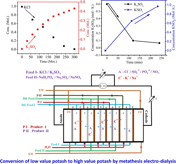
A sustainable approach for the production of high-purity potash fertilizers devoid of chloride is highly needed. Conventional preparation processes for chloride-free potash fertilizers have certain limitations, such as complicated synthesis procedure, including high-temperature requirement, causing environmental pollution. In this work, a novel approach has been proposed for the production of high-purity potash fertilizer (KNO3, K2SO4, and KH2PO4) from KCl by metathesis electrodialysis (MED). Sulfonated poly(ether sulfone)-based cation-exchange membrane and quaternized brominated poly(2,6-dimethyl-1,4-phenylene oxide)-based anion-exchange membranes are used for the MED experiments. The membranes show adequate water uptake, ionic conductivity, and ion-exchange capacity with good mechanical and thermal stabilities. The yields of KNO3, K2SO4, and KH2PO4 are found to be 90, 86, and 90%, respectively. The power consumptions during MED experiment for KNO3, K2SO4, and KH2PO4 are calculated to 0.94, 0.89, and 1.04 kWh/kg, respectively. The purity of products is confirmed by inductively coupled plasma and X-ray diffraction analysis and by measuring ionic contents. The process provides an energy-intensive way for high-purity synthesis of KNO3, K2SO4, and KH2PO4.
Introduction
Potassium is one of the essential macronutrients like nitrogen and phosphorous, which is consumed by plants.1,2 Interestingly, potassium is responsible for more than 60 enzymatic systems in plants that are essentially required for the synthesis of proteins, vitamins, starch, and cellulose. It plays a vital role in photosynthesis, through which plants get energy and control opening and closing of stomata and thus it is required for tissue water balance in plants. However, a deficiency of potassium is recorded in most of the soil, so one can supply potassium to plants as fertilizers. Potash consumption in 2009–2010 in India was 3.33 million tonnes; the demand of fertilizers is ever growing. In 1971–1972, potash consumption in India was 1.90 kg/ha, which upsurged to 17.1 kg/ha in 2008–2009, a 9-fold increase.3 It is essential to produce highly soluble, chlorine-free potassic fertilizers. Potassic fertilizers are mainly categorized into two types: chlorine-containing fertilizers, viz., KCl, and chloride-free fertilizers, such as KNO3, K2SO4, K2HPO4, K2CO3, etc. The most common potassic fertilizer is potassium chloride (KCl), readily recovered from naturally occurring raw materials of potash, which constitutes 90% of potassic fertilizers.4 The use of potassium chloride leads to increase in the chloride content of the soil, excess concentration of which causes toxicity in the crops grown and higher salinity and acidity of the soil.5 The main disadvantage of the presence of chloride in soil is the formation of hazardous compounds by reaction with ammonium nitrate, the most common nitrogenous fertilizer.6 Chloride-free potash fertilizers, such as monopotassium phosphate (KH2PO4), potassium sulfate (K2SO4), potassium nitrate (KNO3), etc., are preferred for chloride-sensitive crops. These potassium salts are rare, usually produced when KCl reacts with nitrate, sulfate, and monobasic phosphate source.7
Potassium nitrate is a highly soluble source, which contains two most common elements, potassium and nitrate, essential for the growth of plants. KNO3 is commonly used in fields where chloride-free potash is required to fulfill the requirement of potash along with nitrate without any further action and other transformation. KNO3 is mainly produced by the reaction of KCl with a nitrate source like sodium nitrate, nitric acid, or ammonium nitrate according to availability and requirement. Industrial production of KNO3 is based on the reaction of KCl and HNO3 in the presence of pentanol.8 Three-fourths of potassium sulfate was also produced by the reaction of KCl and dissolved sulfates or sulfuric acid. Traditional methods for K2SO4 production are the Mannheim method, association–displacement method, and double decomposition method.9,10 The Mannheim method is quite simple with good product yield and quality, but there are several drawbacks, such as strong corrosiveness and abrasiveness of raw materials, high reaction temperature, high energy consumption, and so on. K2SO4 is produced when KCl reacts with ammonium sulfate, and it has high impurity. Zisner et al. also reported the production of K2SO4 by differential contacting process.5 Potassium phosphate is also a highly soluble salt commonly used as fungicide, food additive, and fertilizer. Traditionally, KH2PO4 is produced from phosphoric acid, potassium hydroxide, and water. The reaction between phosphoric acid and potassium hydroxide is highly exothermic. In 1989, Haifa Chemicals Ltd. prepared KH2PO4 using phosphoric acid and potassium chloride in the presence of organic solvent with a long-chain primary amine. Monopotassium phosphate produced by acidulation of phosphoric acid solution and amines is regenerated by calcium oxide or calcium carbonate, but the overall process is not economically viable.11 So, there is a need of a simple and cheap method to produce chloride-free potash.
Electrodialysis (ED) is found to be a potential-driven process used for the separation and recovery of valuable ionic species from aqueous solution without waste generation.12−16 Metathesis electrodialysis (MED) is a modified electrodialysis process that can convert one salt into another by double-ion-replacement reaction. The MED process has many advantages over traditional metathesis reaction, including high purity of product. MED has a great impact where traditional processes are not applicable due to high solubility of both substrate and product or tendency to form double salt.17
The aim of this work was to prepare chloride-free potassic fertilizers by an economically viable and eco-friendly process. Different phosphate, sulfate, and nitrate sources were used along with low-cost potassic fertilizer (KCl) to produce high-value potassium dihydrogen phosphate, potassium sulfate, and potassium nitrate, which are rich sources of potash, nitrogen, sulfur, and phosphorous.
Experimental Section
Materials
Poly(ether sulfone), obtained from Solvay Chemicals Pvt Ltd., India, was used after drying. Poly(2,6-dimethyl-1,4-phenylene oxide) (PPO), N-bromosuccinimide, and N-methylmorpholine were purchased from Sigma-Aldrich. N,N-Dimethyl acetamide, N-methyl-2-pyrrolidone, KCl, NaH2PO4, Na2SO4, and NaNO3 were supplied by S D Fine-Chem Ltd. Double-distilled water was used throughout the experiment.
Methods
Sulfonated poly(ether sulfone) (SPES)-based cation-exchange membrane of thickness 190 μm and quaternized brominated poly(2,6-dimethyl-1,4-phenylene oxide) (QPPO)-based anion-exchange membranes of thickness 160 μm were prepared for MED experiment by previously reported methods.16,18
Chemical, Thermal, Mechanical, and Physicochemical Characterization of Cation Exchange Membranes (CEM) and Anion Exchange Membranes (AEM)
Synthesized CEMs and AEMs were characterized for their chemical, thermal, and mechanical behaviors by Fourier transform infrared (FTIR) spectroscopy, thermogravimetric analysis (TGA), and universal testing machine, respectively. Membranes were physicochemically characterized with their ion-exchange capacity (IEC), ionic conductivity (IC), water uptake, number of water molecules per ionic site (λ), and dimensional stability. Details are given in the Supporting Information section.
Metathesis Electrodialysis (MED) Process for Synthesis of Chloride-Free Potash
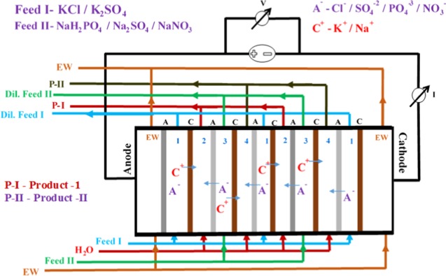
Metathesis electrodialysis (MED) experiments were performed an in-house-made electrodialysis (ED) system having an effective area of 200 cm2, as described in Scheme 1. ED stack contains an alternate arrangement of CEMs and AEMs based on SPES and QPPO, respectively. In ED stack, precious metal-oxide-coated titanium-based electrodes were used. ED has four different compartments, as illustrated in a stack configuration: two feed compartments and two product compartments. The first and third compartments were charged with the feed solution in recirculation mode of 3 L/h, whereas double-distilled water was used in the second and fourth compartments. The turbulence of solutions was maintained at the same flow rate by peristaltic pumps. Na2SO4 solution (0.02 M) was recirculated to avoid electrode reaction. The experiment was conducted with 10 cell pairs of CEMs and AEMs at a constant direct current electrical potential of 2 V/cell pair applied potential. Inductively coupled plasma (ICP) and IC analyses were used for the determination of ionic concentration in the product compartment at a regular interval. I–V curve of CEM and AEM in the MED process was also recorded in equilibration with 0.10 M KCl solution by varying the applied potential from 0 to 5 V/cell pair with the interval of 0.5 V. The specific energy consumption (P) and current efficiency (CE) for production of potassic fertilizers were calculated by standard formula, and the details are given in the Supporting Information section.
Scheme 1. Schematic Representation of Metathesis Electrodialysis (MED) Process for the Production of Chloride-Free Potash.
Results and Discussion
Functional group determination in CEM and AEM was conducted by FTIR spectroscopy, and the corresponding spectra are shown in Figure 1. In spectrum of CEM, the broad absorption band was observed between 3300 and 3500 cm–1 associated with −OH stretching vibrations of water molecules present in association with ionic sites. The absorption band at 1585 cm–1 attributed to the −C=C stretching vibrations of aromatic skeleton of polymer. The two absorption peaks at 1160 and 1103 cm–1 are characteristic of aromatic SO3– stretching vibrations. The peak for aryl oxide appears at 1239 cm–1.19Figure 1 shows the FTIR spectra of AEM; a sharp peak at 1114 cm–1 confirms the quaternization reaction between brominated PPO and N-methylmorpholine. The absorption band at 1600 cm–1 is assigned to the stretching vibration of −C=C– in the phenyl ring present in the polymer backbone. A dominant peak at 1185 cm–1 indicates the stretching of −C–O–C– bond in between the phenyl ring. The absorption band at 1470 cm–1 arises due to symmetric and asymmetric stretching vibrations of the phenyl group.20
Figure 1.
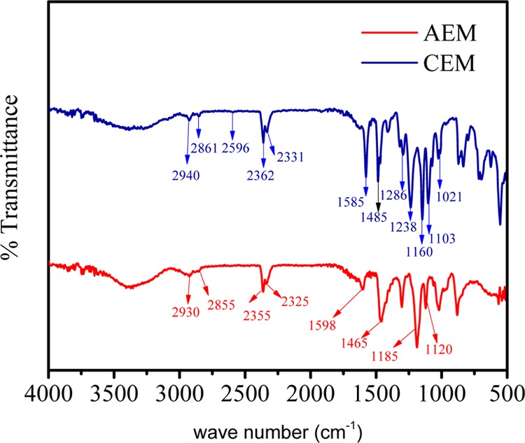
FTIR spectra for ion-exchange membranes.
Thermal stabilities of AEM and CEM were analyzed by TGA, and the corresponding thermograph is presented in Figure 2. Both the membranes have weight losses of 4.39 and 5.83%, respectively, in the temperature range of 80–120 °C due to the presence of water molecules as bound water. Thereafter, weight losses in the temperature range of 200–430 °C for AEM and CEM were found to be 12.48 and 9.58%, respectively, due to degradation of the functional group present as ion-exchange moiety in membranes. The major weight loss was recorded above 450 °C due to degradation of the polymer backbone. The above discussion shows that both AEM and CEM are thermally stable. The stress–strain curves for CEM and AEM in wet and dry states are presented in Figure 3, and the corresponding elastic modulus, tensile strength, and elongation at break are presented in Table 1. Both membranes showed higher tensile strength and elastic modulus in dry condition compared to the wet condition. The measured tensile strength was almost double, and the elastic modulus was 3 times higher than that in the wet condition for both CEM and AEM. The elongation at break in the wet state is found to be higher as water molecules associated with an ionic group present in the membrane matrix show plasticizing behavior in the wet state. The results show that CEM and AEM used were mechanically stable and flexible in nature.
Figure 2.
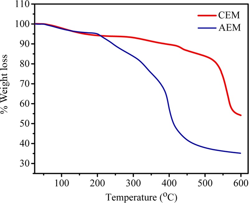
TGA thermograph for ion-exchange membranes.
Figure 3.
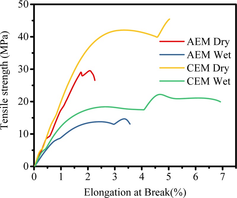
Stress versus strain spectra for ion-exchange membranes.
Table 1. Mechanical Analysis of Ion Exchange Membranes (IEMs) Used for Metathesis Electrodialysis Process.
| membrane type | tensile strength (MPa) | elongation at break (%) | elastic modulus (MPa) |
|---|---|---|---|
| AEM dry | 29.68 | 2.26 | 15.11 |
| AEM wet | 14.88 | 3.59 | 4.88 |
| CEM dry | 45.68 | 5.01 | 9.72 |
| CEM wet | 22.46 | 6.90 | 3.24 |
Table 2 shows the physicochemical and electrochemical properties of IEMs. IEMs should possess a moderate amount of water uptake, high ion-exchange capacity, and high ionic conductivity for efficiency and viability of electromembrane process. Both CEM and AEM show an appreciable amount of mass gain when equilibrated with water, with values of 12.12 and 27.7%, respectively. Water uptake by IEMs determines the movement of counterion and mechanical stability of membranes. Higher water uptake leads to poor mechanical stability of IEM, whereas moderate amount of water in the membrane retains the stability along with high transport of ions. Ion-exchange capacity (IEC) represents the number of ion-exchange groups present in IEMs. IECs for CEM and AEM were calculated to be 1.40 and 2.15 meq/g, respectively. With the boost of ion-exchangeable groups, water molecules per unit ionic site also increases. Water molecules present in matrix interconnect the ionic channels, which enhances the transport of counterions. The ionic conductivity (IC) of IEMs determines the feasibility of membrane under electromembrane process. Higher ionic conductivity results in the lower power consumption, which favors product formation. The calculated IC values for both CEM and AEM are 3.15 × 10⁻² and 1.30 × 10⁻² S/cm, respectively, which well matched the values reported in the literature.16,18
Table 2. Water-Related Assets, Ion-Exchange Capacity (IEC), and Ionic Conductivity (IC) of IEMs.
| IEM | IEC (meq/g) | IC × 10–2 (S/cm) | WU (%) | λ |
|---|---|---|---|---|
| CEM | 1.40 | 3.15 | 12.12 | 4.80 |
| AEM | 2.15 | 1.30 | 27.70 | 4.02 |
Current–voltage characteristic of IEMs are taken from 0.5 to 4.5 V/cell pair after equilibrating the IEMs in 0.1 M salt solution and are presented in Figure 4. Three characteristic regions are found, viz, ohmic, plateau, and nonohmic. These regions represent the characteristics of IEMs in terms of ion-transport mechanism and concentration polarization phenomenon. From the figure, it is clear that current is directly proportional to applied voltage and thus obeys Ohm’s law in the ohmic region due to the presence of a large number of ions in solution, whereas in the plateau region, current becomes almost constant, which shows concentration polarization. Thereafter, in the nonohmic region, current rises steeply due to dissociation of water molecules at higher applied potential. It was concluded that our region of interest is the plateau region and that whole MED experiments were carried out in this region.
Figure 4.
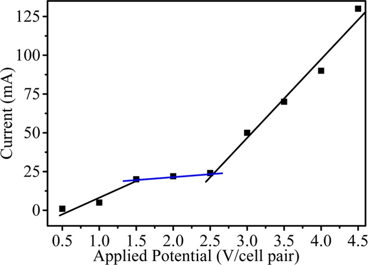
Current against applied potential for MED process.
K2SO4 is produced during MED using KCl and Na2SO4 reactants at 2 V/cell pair applied potential across the electrodes. During the conversion process, a 2:1 stoichiometric ratio of KCl and Na2SO4 was used. The overall stoichiometric equation for K2SO4 synthesis is given below
Figure 5 shows the current density value vs time for different feed concentrations. The current density value first increases and then decreases with time due to the higher concentration gradient between feed and product compartments. However, over time, concentration of ions gradually decreases and maintains equilibrium in both the compartments, which leads to decrease in the current density. From the graph, it can be seen that the current density value is higher for feed with 1.0 M concentration than for feed with 0.2 M concentration. Figure 6 shows the conversion of K2SO4 from KCl with respect to time during MED. Herein, K2SO4 is a product formed by the ion-displacement reaction of KCl and Na2SO4. The concentrations of Na2SO4 and KCl as well as the applied voltage for the migration of ions have been optimized during the whole process. The feed was filled in compartments 1 and 3 (KCl and Na2SO4), while deionized water was filled in compartments 2 and 4. Double-displacement reaction takes place between KCl and Na2SO4, and the formation of products K2SO4 and NaCl occur in compartments 2 and 4, respectively. The migration of K+ and SO42– starts from compartments 1 and 3, respectively, to compartment 2 as we apply potential. From the graph, it can be easily seen that the concentration of KCl decreases with time; on the other hand, the concentration of K2SO4 increases. The initial concentration of KCl in the first compartment was 0.99 M, but as a result of migration of ions, this concentration was reduced to 0.69 M after 30 min. Simultaneously, the concentration of K2SO4 (0.15 M) in compartment 3 revealed the formation of product. The runtime of the experiment was 5 h, where the concentration of the product was found to be about 0.43 M. In the same time, migration of Na+ and Cl– occurs from compartments 3 and 1, respectively, to compartment 4 to form NaCl (Scheme 1). Figure 7 shows the formation of NaCl during MED. The formation of K2SO4 as a product takes place in the second compartment, whereas the formation of NaCl takes place in the fourth compartment. The formation of NaCl enhances the product formation due to the higher depletion of ions from their respective reactant compartments, so the respective product shall increase. Figure 7 (inset) focuses on the effect of optimized voltage on the product conversion. It is clear from the graph that the formation of product is higher when applied voltage is 2.5 V/cell pair compared to 2 V/cell pair. Solid K2SO4 crystals were obtained by evaporating the water from the product compartment solution obtained by the MED process. Figure 8 shows the X-ray diffraction (XRD) pattern of synthesized K2SO4. Peaks at 2θ values of 21.6, 29.95, 30.93, and 43.44 are attributed to the structure of arcanite, which well matched with the literature.5,9 The purity of K2SO4 crystals has also been checked by ICP analysis of the dried solid material.
Figure 5.
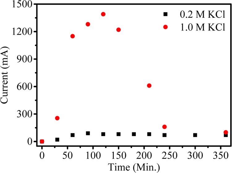
Current density versus time during production of K2SO4 by metathesis electrodialysis (MED) process at 2 V/cell pair.
Figure 6.
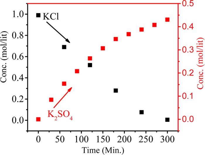
Dependence of KCl and K2SO4 concentrations on time during production of K2SO4 by metathesis electrodialysis (MED) process with 1 M KCl and 0.5 M Na2SO4 at 2 V/cell pair.
Figure 7.
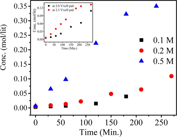
Effect of KCl concentration on production of NaCl. The inset shows the effect of potential.
Figure 8.
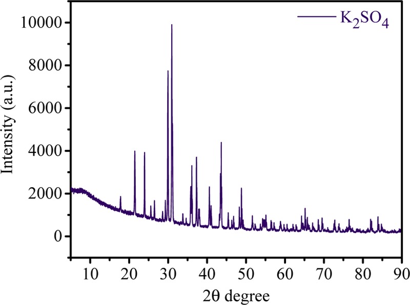
XRD pattern of synthesized K2SO4 by metathesis electrodialysis (MED) process.
Highly valuable potassium nitrate was synthesized by MED experiment using 0.6 M K2SO4 and 1.2 M NaNO3 as feed solutions for compartments 1 and 3, respectively, whereas DI water was used in the other two compartments (Scheme 1). The experiments were carried out at applied voltages of 1.5 and 2 V/cell pair. K+ from feed 1 migrated to compartment 2, and NO3– migrated from feed 3 to compartment 2, leading to dilution of feed 1 and feed 3, whereas concentrating compartment 2 with KNO3. Similarly, Na+ migrated from feed 2 to compartment 4 and SO42– migrated from feed 1 to compartment 4, concentrating with Na2SO4. The overall equation for the production of KNO3 using MED process is shown below
Figure 9A,B shows the conversion of KNO3 from K2SO4 with time at applied potentials of 1.5 and 2.0 V/cell pair, respectively. Initially, after 2 h at 1.5 V/cell pair, the concentration of KNO3 in compartment 2 was 0.57 M, whereas the concentration of K2SO4 in compartment 1 reduced to 0.21 M. Initially, ion migration was quick because of higher concentration of ions in compartments 1 and 3 and hence the formation of KNO3 in compartment 2 was higher, and after 2 h of experiment, no significant change was observed in the concentration of KNO3. Over time, the concentration difference of ions in both the compartments decreased so that migration of ions became slow. At 2.0 V/cell pair applied potential (Figure 9B), the overall production of KNO3 increased. The concentration of KNO3 increased efficiently to 0.65 mol/L in the small interval of 2 h, which was quite higher than that during the production at 1.5 V/cell pair. Over time, ion migration from feed compartment to product compartment was rapid, and finally, the concentration of KNO3 in product compartment was found to be 0.97 M, whereas the concentration of K2SO4 decreased from 0.6 to 0.066 M. Figure 10 presents the concentration of Na2SO4 in the fourth compartment at applied voltages of 1.5 and 2 V/cell pair. From the figure, it is clear that 2 V/cell pair applied voltage is more effective in production of KNO3 and Na2SO4 as byproduct. The Na2SO4 produced in this process was used in the former process for the synthesis of K2SO4. To check the purity of KNO3, XRD analysis was carried out and the result is presented in Figure 11. Crystalline KNO3 was obtained by evaporating water from product compartment solution produced during MED experiment. Diffraction peaks at 27.8, 32.37, 34.43, and 47.55 were found to be associated with the crystal structure of KNO3.21 The purity of the product was also checked by ICP analysis of the dried solid material. This shows the production of high-purity KNO3 during MED without impurity.
Figure 9.
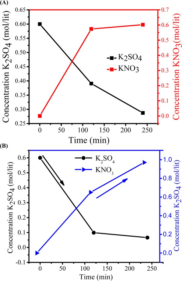
(A) Dependence of K2SO4 and KNO3 concentrations on time during production of KNO3 by metathesis electrodialysis (MED) process with 0.6 M K2SO4 and 1.2 M NaNO3 at 1.5 V per cell pair applied potential. (B) Dependence of K2SO4 and KNO3 concentrations on time during production of KNO3 by metathesis electrodialysis (MED) process with 0.6 M K2SO4 and 1.2 M NaNO3 at 2 V per cell pair applied potential.
Figure 10.
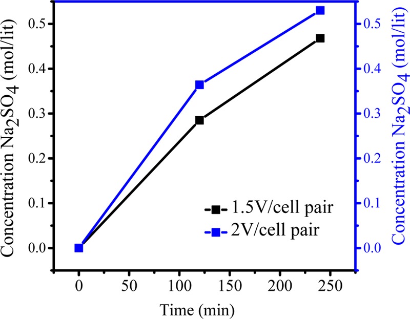
Effect of applied potential during the production of Na2SO4 by metathesis electrodialysis (MED) process.
Figure 11.
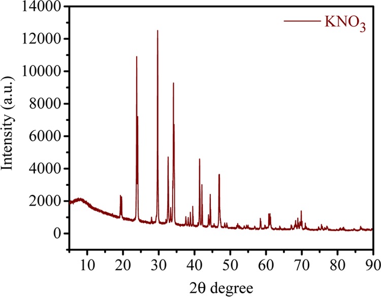
XRD pattern of synthesized KNO3 by metathesis electrodialysis (MED) process.
KH2PO4 from KCl and NaH2PO4 was also synthesized by MED, with NaCl formed as byproduct, as presented in the following equation
From the above equation, it is clear that 1:1 molar ratio is required for completion of reaction. Different feed concentrations of KCl were used to evaluate the quantitative yield of KH2PO4. During MED process, 0.1, 0.2, and 0.5 M KCl and NaH2PO4 were used as feed solution in compartments 1 and 3, respectively, whereas DI water was used in compartments 2 and 4 (Scheme 1). Scheme 1 shows the arrangement of ion-exchange membranes and different compartments during MED process; for applied voltage, K+ ion migrated from feed compartment 1 to product compartment 2, whereas H2PO4– migrated from compartment 3 to compartment 2, leading to the formation of KH2PO4 in the product compartment. Similarly, in the fourth compartment, the concentrations of Cl– and Na+ increased over time, forming NaCl as byproduct. Figure 12 (inset) shows the decrease of KCl concentration with time. On applying a constant potential of 2 V/cell pair, for different feed concentrations of 0.1, 0.2, and 0.5 M KCl, the concentration of KCl decreased from the initial value to 0.007, 0.05, and 0.16 M, respectively, after 2 h. Figure 12 shows the concentrations of KH2PO4 for different feed concentrations after 2 h of MED process as 0.061, 0.11, and 0.24 M for feed solutions of 0.1, 0.2, and 0.5 M, respectively, whereas after 4 h, the concentrations reached 0.095, 0.16, and 0.36 M, respectively. Nearly 90% conversion in the experiment was completed in a span of 4 h. Figure 13 (inset) shows the reduction in the concentration of NaH2PO4 with time for different feed concentrations of 0.1, 0.2, and 0.5 M. From the figure, it is clear that reduction is very fast at higher concentration than at lower concentrations. After 4 h of experiment, the concentrations of NaH2PO4 in compartment 3 were 0.0015, 0.0038, and 0.086 for feed concentrations of 0.1, 0.2, and 0.5 M, respectively. Figure 13 shows the production of NaCl as byproduct in the fourth compartment for 0.1, 0.2, and 0.5 M concentrations of NaH2PO4; the yield of byproduct in the fourth compartment was higher than 90%. It was observed from Figures 12 and 13 that 0.1 M feed concentrations of KCl and NaH2PO4 required relatively less time for conversion to KH2PO4 and NaCl, whereas higher feed concentration of 0.5 M required more time for the conversion. The number of co-ions increases in the solution at higher concentration, which is responsible for the sluggish movement of ions. Co-ion transport across the membrane during the MED process regulates the quality of product, but no co-ion transport was observed throughout the process.8
Figure 12.
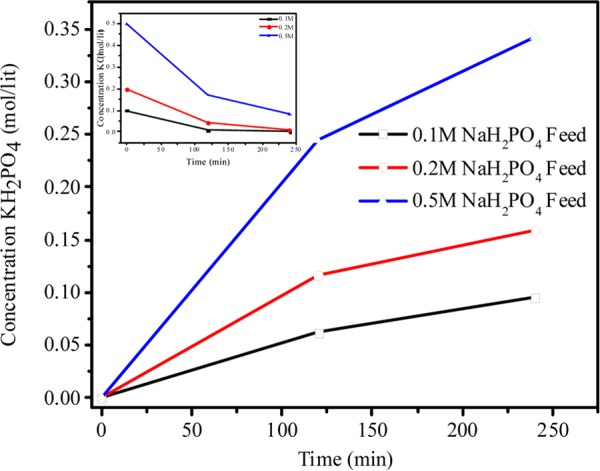
Change in concentration of KH2PO4 with time, with different feed concentrations of NaH2PO4 and KCl during metathesis electrodialysis (MED) process with 2 V per cell pair applied potential.
Figure 13.
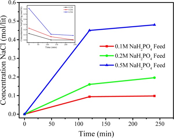
Change in concentration of NaCl with time, with different feed concentrations of KCl and NaH2PO4 during metathesis electrodialysis (MED) process at 2 V per cell pair applied potential.
Energy consumption and current efficiency data were evaluated for the performance of MED experiment during conversion of K2SO4, KNO3, and KH2PO4 with 2 V/cell pair applied potential, and the results are presented in Table 3. The CE and P at 2 V potential are found to be 82% and 0.94 kWh/kg, respectively, for K2SO4 production, whereas 87.0% and 0.89 kWh/kg, respectively, for KNO3. The lowest CE and higher power consumption were calculated for the KH2PO4 synthesis, which were 81% and 1.04 kWh/kg, respectively. The 2 V/cell pair applied potential was found to be most suitable for the production of chloride-free potash by MED experiment.
Table 3. Energy Consumption (P) and Current Efficiency (CE %) for Production of Chloride-Free Potash at 2 V/Cell Pair Applied Potential.
| salt produced | P (kwh/kg) | CE % |
|---|---|---|
| K2SO4 | 0.94 | 82 |
| KNO3 | 0.89 | 87 |
| KH2PO4 | 1.04 | 81 |
Conclusions
A novel synthesis approach, metathesis electrodialysis, is developed to obtain high-value potassic fertilizers (K2SO4, KNO3, and KH2PO4) with high purity to overcome the limitations of conventional approaches. Quaternized poly(2,6-dimethyl-1,4-phenylene oxide)-based AEM and sulfonated poly(ether sulfone)-based CEM at an applied voltage of 2 V/cell pair were used for the MED process. AEM and CEM show good physicochemical and electrochemical properties with good thermal and mechanical stabilities and are found to be suitable for MED process due to their low electro-osmotic drag. Stoichiometric ratios of the reactant of 2:1, 2:1, and 1:1 for the production of K2SO4, KNO3, and KH2PO4, respectively, provide optimum results. MED shows low power consumption and good current efficiency of the order of 1 kWh/kg and 80%, respectively, for the production of potassic fertilizer. The obtained product is confirmed to be of high purity by XRD. The byproduct formed during the synthesis of KNO3 (Na2SO4) is utilized for the formation of K2SO4 by MED. In brief, MED is an environmentally friendly and less expensive process to produce high-purity potassic fertilizers.
Acknowledgments
V.K. acknowledges Department of Science and Technology, New Delhi, for financial support. The authors also acknowledge Analytical Discipline and Centralized Instrument facility, CSMCRI, Bhavnagar, for instrumental support.
Supporting Information Available
The Supporting Information is available free of charge on the ACS Publications website at DOI: 10.1021/acsomega.8b01005.
Synthesis of membranes; chemical, structural, and physiochemical characterization; and energy consumption (Sections S1–S4) (PDF)
Author Contributions
∥ P.P.S. and V.Y. contributed equally to this work.
The authors declare no competing financial interest.
Supplementary Material
References
- Making Chloride-free potash fertilizers Phosphorus Potassium 1988, 156, 27−34.
- Grzmil B. U.; Kic B. Single-Stage Process for Manufacturing of Potassium Sulphate from Sodium Sulphate. Chem. Pap. 2005, 59, 476–480. [Google Scholar]
- Kinkar B. K. Potassium fertilizer situation in India: Current use and perspectives. Karnataka J. Agric. Sci. 2011, 24, 1–6. [Google Scholar]
- Dave R. H.; Ghosh P. K. Efficient Recovery of Potassium Chloride from Liquid Effluent Generated during Preparation of Schoenite from Kainite Mixed Salt and It’s Reuse in Production of Potassium Sulfate. Ind. Eng. Chem. Res. 2006, 45, 1551–1556. 10.1021/ie050433g. [DOI] [Google Scholar]
- Trivedi J. S.; Bhadja V.; Makwana B. S.; Jewrajka S. K.; Chatterjee U. Sustainable process for the preparation of potassium sulfate by electrodialysis and its concentration and purification by a nanofiltration process. RSC Adv. 2016, 6, 71807–71817. 10.1039/C6RA14303B. [DOI] [PMC free article] [PubMed] [Google Scholar]
- Han X.; Yan X.; Wang X.; Ran J.; Wu C.; Zhang X. Preparation of chloride-free potash fertilizers by electrodialysis metathesis. Sep. Purif. Technol. 2018, 191, 144–152. 10.1016/j.seppur.2017.09.022. [DOI] [Google Scholar]
- Joshi C. S.; Shukla M. R.; Patel K.; Joshi J. S.; Sahu O. Environmentally and Economically Feasibility Manufacturing Process of Potassium Nitrate for Small Scale Industries: A Review. Int. Lett. Chem., Phys. Astron. 2015, 41, 88–99. 10.18052/www.scipress.com/ILCPA.41.88. [DOI] [Google Scholar]
- Sharma P. P.; Gahlot S.; Rajput A.; Patidar R.; Kulshrestha V. Efficient and Cost Effective Way for the Conversion of Potassium Nitrate from Potassium Chloride Using Electrodialysis. ACS Sustainable Chem. Eng. 2016, 4, 3220–3227. 10.1021/acssuschemeng.6b00248. [DOI] [Google Scholar]
- Zhang X.; Wang X.; Liu X.; Han X.; Jiang C.; Li Q.; Xu T. Conversion of Potassium Chloride into Potassium Sulfate by Four-Compartment Electrodialysis: Batch Operation Process. Ind. Eng. Chem. Res. 2015, 54, 11937–11943. 10.1021/acs.iecr.5b03245. [DOI] [Google Scholar]
- Worthington R. E.; Haven W.; Magdics A.; Stain D. B. U.S. Patent US4588573A1986.
- Iannicelli J.; Pechtin J. U.S. Patent US7601319B22009.
- Selvaraj H.; Aravind P.; Sundaram M. Four compartment mono selective electrodialysis for separation of sodium formate from industry wastewater. Chem. Eng. J. 2018, 333, 162–169. 10.1016/j.cej.2017.09.150. [DOI] [Google Scholar]
- Xu X.; He Q.; Ma G.; Wang H.; Nirmalakhandan N.; Xu P. Selective separation of mono- and di-valent cations in electrodialysis during brackish water desalination: Bench and pilot-scale studies. Desalination 2018, 428, 146–160. 10.1016/j.desal.2017.11.015. [DOI] [Google Scholar]
- Sharma P. P.; Yadav V.; Maru P. D.; Makwana B. S.; Sharma S.; Kulshrestha V. Mitigation of Fluoride from Brackish Water via Electrodialysis: An Environmentally Friendly Process. ChemistrySelect 2018, 3, 779–784. 10.1002/slct.201701170. [DOI] [Google Scholar]
- Srivastava N.; Joshi K. V.; Thakur A. K.; Menon S. K.; Shahi V. K. BaCO3 nanoparticles embedded retentive and cation selective membrane for separation/recovery of Mg2+ from natural water sources. Desalination 2014, 352, 142–149. 10.1016/j.desal.2014.08.014. [DOI] [Google Scholar]
- Yadav V.; Sharma P. P.; Kulshrestha V. Facile synthesis of Br-PPO/f GO based polymer electrolyte membranes for electrochemical applications. Int. J. Hydrogen Energy 2017, 42, 26511–26521. 10.1016/j.ijhydene.2017.08.029. [DOI] [Google Scholar]
- Pisarska B. Transport of co-ions across ion exchange membranes in electrodialytic metathesis MgSO4 + 2KCl → K2SO4 + MgCl2. Desalination 2008, 230, 298–304. 10.1016/j.desal.2007.10.021. [DOI] [Google Scholar]
- Gahlot S.; Sharma P. P.; Kulshrestha V.; Jha P. K. SGO/SPES-Based Highly Conducting Polymer Electrolyte Membranes for Fuel Cell Application. ACS Appl. Mater. Interfaces 2014, 6, 5595–5601. 10.1021/am5000504. [DOI] [PubMed] [Google Scholar]
- Klaysom C.; Ladewig B. P.; Max Lu G. Q.; Wang L. Preparation and characterization of sulfonated polyethersulfone for cation-exchange membranes. J. Membr. Sci. 2011, 368, 48–53. 10.1016/j.memsci.2010.11.006. [DOI] [Google Scholar]
- Khan M. I.; Mondal A. N.; Tong B.; Jiang C.; Emmanuel K.; Yang Z.; Wu L.; Xu T. Development of BPPO-based anion exchange membranes for electrodialysis desalination applications. Desalination 2016, 391, 61–68. 10.1016/j.desal.2015.11.024. [DOI] [Google Scholar]
- Deng Y.; Li J.; Qian T.; Guan W.; Wang X. Preparation and Characterization of KNO3/diatomite Shape-stabilized Composite Phase Change Material for High Temperature Thermal Energy Storage. J. Mater. Sci. Technol. 2017, 33, 198–203. 10.1016/j.jmst.2016.02.011. [DOI] [Google Scholar]
Associated Data
This section collects any data citations, data availability statements, or supplementary materials included in this article.


