Abstract
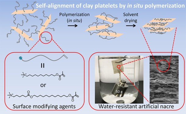
Fabrication and characterization of water-resistant nacre-like polymer/clay nanocomposites, in which clay platelets and hydrophobic polymer chains are alternately stacked in parallel, are reported. Hydrophilic clay was converted by an ion-exchange reaction with a methacrylate monomer having a long alkyl chain and a quaternary ammonium salt group at the end. The subsequent in situ polymerization bound the neighboring clay surfaces, leading to the preferential orientation of the clay platelets owing to their high aspect ratio. The composites maintained excellent mechanical properties even after being immersed in water for more than a day. Strong shape stability was observed in water as well as in various organic solvents.
Introduction
Nacre, a natural composite material that forms the inner layer of sea shells, has attracted much attention as a model for high-performance composites because of its extreme hardness and toughness.1−3 It consists mainly of platelet-like aragonite (CaCO3, ∼95 vol %) and a small amount of biopolymers alternately stacked to form a well-defined layered structure, rendering excellent mechanical performance.4,5 This unique combination of organic and inorganic substances provides inspiration for new composite materials having high mechanical performance. Various inorganic fillers with a high aspect ratio, such as clay,6−10 graphene,11−14 and Al2O3 platelets,15,16 have been used to mimic nacre in composites. Clay is particularly widely used because it is naturally occurring, inexpensive, and abundant. Nacre-like polymer/clay composites with extraordinary mechanical properties have been realized by techniques such as layer-by-layer assembly,6,7 water evaporation assembly occurring at an air/water interface,8,9 vacuum filtration assembly,10 doctor-blade assembly,10 and so on. To obtain an ideal mixture of clay and polymer, these techniques utilize an aqueous solution of a polymer as well as an aqueous dispersion of clay. Water-soluble polymers such as poly(diallyldimethylammonium chloride),6 poly(vinyl alcohol),8−10 polyethylene oxide,17 carboxymethyl cellulose,18 and xyloglucan19 have been used in previous studies. The composites thus developed showed good mechanical properties only under low ambient humidity. At higher humidity, these waterborne nacre-like composites were hydrated, and their mechanical performances were drastically weakened.20
In recent years, some efforts have been made to overcome the humidity and/or water sensitivity of polymer/clay nacre-like composites by chemical/physical cross-linking18,19,21 and hydrophobic surface coating.22,23 Cross-linking in the polymer layer and at the interface obtained by ionic18 and covalent19,21 bonds preserved mechanical properties to some extent even at high humidity because of the improved rigidity18,19 of the polymer layer and the enhanced interaction at the interface.21 Notably, the introduction of covalent cross-links through dopamine treatment in a cellulose nanofibrils/clay composite provided good mechanical properties even under water.21 However, immersion in water drastically decreased the material’s Young’s modulus and tensile strength by 91 and 84%, respectively. Although previous approaches have lowered the sensitivity to humidity, the resistance under water is still limited because they use water-soluble or water-dispersible polymers as matrix polymers. Therefore, to enhance the water resistance more fundamentally, we completely changed the approach and employed a hydrophobic polymer. To introduce a hydrophobic polymer into nacre-like composites, we modified the originally hydrophilic clay surface with a hydrophobic monomer followed by in situ polymerization; this led to hydrophobic polymer chains covering the clay plates and the establishment of a connection between the surfaces of the clay platelets. Owing to the high aspect ratio of the clay, the clay platelets were self-aligned to a layered structure. As the clay component, we chose sodium montmorillonite (MMT), on which sodium cations can be exchanged using a hydrophobic methacrylate monomer with a long alkyl chain and organic quaternary ammonium salt group.24 The resultant composite material maintained excellent mechanical properties even under water. In addition, it exhibited shape stability in various organic solvents including both hydrophilic and hydrophobic solvents. To the best of our knowledge, this is the first work that combines a hydrophobic polymer with clays to form a nacre-like composite.
Results and Discussion
Surface Modification of MMT
MMT belongs to the smectite group of clay and is made up of one octahedral alumina sheet sandwiched between two tetrahedral silica sheets. MMT is ionic and hydrophilic.24 To obtain water-resistant composites with MMT, MMT was modified by cation-exchange reaction with hydrophobic surface-modifying agents [i.e., 11-(methacryloyloxy)undecyltrimethylammonium bromide (UMTA) or 12-(methacryloyloxy)dodecyl 6-(hexanoyloxy)trimethylammonium bromide (DHTA)] having a methacryloyl group on one end of a long alkyl chain and a quaternary ammonium group on the other end.24 The chemical structures of the surface modifiers and a schematic of the MMT surface modification process are shown in Figure 1.
Figure 1.
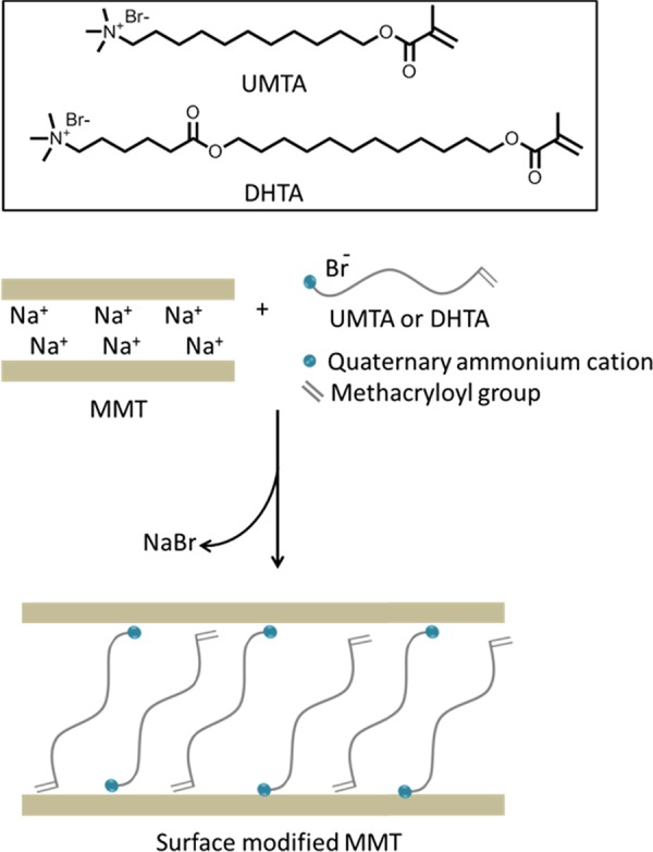
Chemical structures of the surface modifiers and a schematic of the surface modification of MMT.
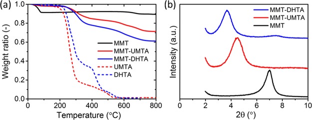
The amount of the surface modifier on MMT was evaluated using thermogravimetric analysis (TGA) (Figure 2a). The TGA curve of the pristine MMT shows a drop at <100 °C which corresponds to the release of adsorbed water. No further weight loss appears until 635 °C, where a drop is observed owing to the loss of OH groups and crystallographic-structure collapses in MMT.25 The TGA curves of the surface modifiers, UMTA and DHTA, show a weight drop between 200 and 600 °C owing to the thermal decomposition. The modified clays, MMT–UMTA and MMT–DHTA, also exhibit considerable weight loss between 200 and 600 °C because of the decomposition of the surface modifier. From these weight losses, the amounts of DHTA in MMT–DHTA and UMTA in MMT–UMTA were estimated to be 29.5 and 20.8 wt %, respectively. For these modified clays, the weight loss at <100 °C is trivial, showing that the amount of water in the clays is negligible (approximately 1 wt %). The cation-exchange efficiency of the modified clays can be calculated as26
| 1 |
where fCE is the fraction of the cation that is exchanged by the surface modifier, M is the molecular weight of the surface modifier, S is the percentage weight loss by the decomposition of the surface modifier during TGA analysis, and C is the cation-exchange capacity of pristine MMT (115 cmol kg–1). For MMT–UMTA, by applying M = 298.49 g mol–1 and S = 20.8 wt %, fCE was found to be 0.77. For MMT–DHTA, fCE was found to be 0.85 by applying M = 426.66 g mol–1 and S = 29.5 wt %. The cation-exchange efficiencies for MMT–UMTA and MMT–DHTA were similar to those of the other surface-modified MMTs in previous reports.26,27 MMT–DHTA had larger fCE than MMT–UMTA owing to the stronger hydrophobic interaction between adjacent modifiers in MMT–DHTA and MMT–DHTA’s longer alkyl chain.28,29
Figure 2.
(a) TGA curves for MMT, MMT–UMTA, and MMT–DHTA, as well as UMTA and DHTA. (b) One-dimensional (1D) X-ray diffraction (XRD) profiles of MMT, MMT–UMTA, and MMT–DHTA.
The interlayer distance (d spacing) before and after the surface modification was analyzed by 1D XRD measurements (Figure 2b). From the peak position in 1D XRD profiles, the d spacing of MMT was estimated to be 1.14 nm, which corresponds to the values reported in previous papers.30−33 By surface modification, the d spacing was enlarged: d = 1.98 nm for MMT–UMTA and 2.40 nm for MMT–DHTA. This strongly suggests that the surface modifier was successfully inserted in the interlayers of MMT. The longer alkyl chain of DHTA results in a larger d spacing in MMT–DHTA compared to that in MMT–UMTA.32
Attenuated total reflection–Fourier transform infrared (ATR–FTIR) measurements were performed to further confirm the surface modification of MMT (Figure S3 and Table S1). Bands associated with both pristine MMT and surface modifiers were observed in the spectra of MMT–UMTA and MMT–DHTA, whose assignments are listed in Table S1, referring to previous reports.34−37
The results of TGA, 1D XRD, and ATR–FTIR measurements clearly show that the cation-exchange reaction had indeed occurred, and MMT was successfully modified with UMTA or DHTA.
Fabrication of Nacre-Like Structure via in Situ Polymerization
MMT–UMTA and MMT–DHTA are dispersible in dimethylacetamide (DMA), and the suspensions are stable for over one month. Therefore, the methacryloyl group of UMTA and DHTA on the surfaces of MMT was polymerized in DMA. By adding a photoinitiator to the suspension and irradiating it with UV light, a gel-like deposit (MMT–pUMTA_gel and MMT–pDHTA_gel) was obtained (Figure S4), which was then dried to yield the final composite films, MMT–pUMTA and MMT–pDHTA.
As the first step of the characterization of the products, we tried to confirm the polymerization of the surface modifiers. The reverse ion-exchange technique38−40 was used to cleave the organic molecules from the clay surfaces. The 1H NMR spectra of the organic residues obtained from MMT–pUMTA and MMT–pDHTA (Figure S5) indicate a lack of C=C double bonds that originally existed in the surface modifiers, UMTA and DHTA, respectively. In addition, the spectra are identical to hpUMTA and hpDHTA obtained by the free-radical polymerization of each monomer. These facts clearly indicate that UV irradiation induces the polymerization of the surface modifier and leads to binding of the MMT platelets, thus yielding gel-like deposits.
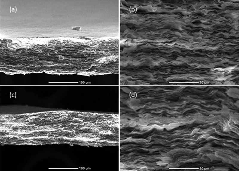
The scanning electron microscopy (SEM) images in Figure 3 show the cross-sectional morphologies of MMT–pUMTA and MMT–pDHTA. Prior to the observation, the cross-sectional samples were prepared by the freeze-fracture technique, in which the samples were frozen in liquid nitrogen and cracked to obtain fresh cross sections. A nacre-like structure is observed in both composite films, illustrating the parallel alignment of MMT platelets.
Figure 3.
SEM images of the cross section of MMT–pUMTA with the scale bar of (a) 100 and (b) 10 μm and MMT–pDHTA with the scale bar of (c) 100 and (d) 10 μm.
Analysis of Structural Evolution During in Situ Polymerization
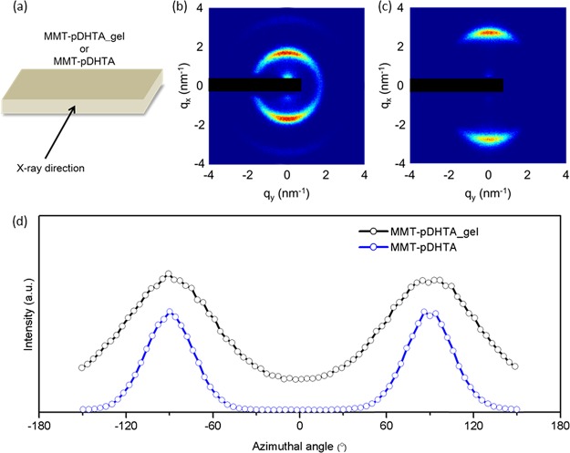
We further investigated the structural evolution during the fabrication of MMT–DHTA. First, two-dimensional (2D) XRD measurements were carried out to clarify the orientation of MMT platelets in the gel-like deposit (MMT–pDHTA_gel) and the composite film (MMT–pDHTA). X-rays were emitted in a direction parallel to the plane of each film-like sample, as illustrated in Figure 4a. Figure 4b,c shows the 2D XRD images of MMT–pDHTA_gel and MMT–pDHTA, respectively. In both images, the (001) diffraction forms anisotropic arcs concentrated on the meridian, indicating that the (001) plane of MMT is oriented parallel to the film surface. Although the orientation is qualitatively similar, the radial peak position and the azimuthal width of the (001) diffraction are quantitatively different in MMT–pDHTA_gel and MMT–pDHTA. The peaks of MMT–pDHTA_gel are situated at a higher angle than those of MMT–pDHTA, indicating the decrease of d spacing upon drying of the gel-like deposit. The change in the d spacing will be discussed quantitatively using 1D XRD later in this section. The azimuthal width of the diffraction arcs reflects the orientation degree of the MMT platelets. Figure 4d shows the azimuthal intensity profile of the (001) diffraction arcs. The peaks of MMT–pDHTA are sharper than that of MMT–pDHTA_gel, indicating that MMT–pDHTA had a higher orientation degree than MMT–pDHTA_gel. In fact, the full-width at half-maximum of the peaks was 39° and 71° for MMT–pDHTA and MMT–pDHTA_gel, respectively. The incomplete orientation of MMT platelets in the gel-like deposit, possibly due to the remaining DMA between the platelets, should improve upon the complete removal of DMA.
Figure 4.
(a) Schematic of the sample geometry for 2D XRD measurements. 2D XRD images of (b) MMT–pDHTA_gel and (c) MMT–pDHTA. The direct beam and shadow of the beam stopper are masked with a black rectangle. (d) Azimuthal intensity profiles of the diffraction arcs in (b,c). The origin of the azimuthal angle was taken to be the horizontal axis of the 2D XRD images.
The MMT platelets were self-aligned in the layered structure during the formation of the gel-like deposits, possibly because of the high aspect ratio of MMT, which can make the probability of contact between the surfaces much larger than that between the sides and that between the side and the surface. Therefore, in situ polymerization would bind two clay surfaces, producing an aggregation consisting of alternate layers of clay platelets and polymer layers. Repeated reactions between the clay surfaces would increase the aggregation size while maintaining the plate-like shape and eventually lead to the deposition on the substrate surface in a manner akin to how a leaf falls to the ground, that is, while maintaining the parallel orientation of the MMT platelets. The absence of free monomers or polymers in the reaction system may also contribute to the formation of the layered structure.
The d spacing of the MMT platelets was evaluated by 1D XRD. Figure S6 shows 1D XRD profiles of the surface-modified clays (MMT–UMTA and MMT–DHTA), gel-like deposits (MMT–pUMTA_gel and MMT–pDHTA_gel), and composite films (MMT–pUMTA and MMT–pDHTA). The positions of the (001) diffraction peaks and the corresponding d spacings are listed in Table S2. The d spacings of MMT–DHTA, MMT–pDHTA_gel, and MMT–pDHTA are 2.40, 4.00, and 2.44 nm, respectively. MMT–pDHTA_gel has the largest d spacing because pDHTA is swollen by DMA. MMT–DHTA showed the smallest value among these materials because the alkyl chains of DHTA are arranged obliquely on clay platelets, allowing efficient nanoscale packing of the molecules.41 The value for MMT–pDHTA is similar to but slightly larger than that for MMT–DHTA, indicating that the MMT platelets in MMT–pDHTA were less densely packed compared to MMT–DHTA, possibly because of the reduced conformational freedom of the surface modifier by polymerization. A similar tendency was observed in the d spacings of MMT–UMTA, MMT–pUMTA_gel, and MMT–pUMTA.
From the above structural characterization results, we summarize the possible formation mechanism of the nacre-like structure schematically in Figure 5. The modified clay platelets, MMT–UMTA or MMT–DHTA, are initially dispersed in DMA. The surface modifier, UMTA or DHTA, on the MMT surface is then polymerized, leading to the aggregation and precipitation of clay platelets into the gel-like deposit at the bottom of the container. The high aspect ratio of MMT facilitates the self-alignment of MMT platelets during the formation of the gel-like deposit. By removing the remaining DMA, the orientation degree of the MMT platelets increases, thus yielding the final composite films with a nacre-like structure.
Figure 5.
Possible mechanism of self-alignment of MMT platelets by in situ polymerization.
Shape Stability of Composite Films in Various Solvents
We investigated the shape stability of the composite films in various solvents. We selected water, methanol, acetone, and chloroform as solvents, to include both hydrophilic and hydrophobic solvents. The composite films, MMT–pUMTA and MMT–pDHTA, were immersed in each solvent and sonicated for 5 h. Figure 6 shows the photographs of MMT–pDHTA before and after sonication. Neither film collapse nor significant volume change was observed in all samples, indicating shape stability.
Figure 6.
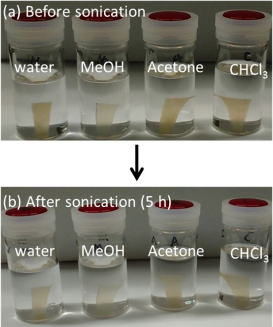
Photographs of MMT–pDHTA in water, methanol, acetone, and chloroform (a) immediately after immersion and (b) after 5 h sonication.
The shape stability of MMT–pDHTA in hydrophilic solvents could be ascribed to the hydrophobicity of MMT–DHTA. Although DHTA is soluble and MMT is dispersible in both water and methanol, MMT–DHTA is not dispersible in these solvents owing to covering by a hydrophobic alkyl chain. In hydrophobic solvents such as acetone and chloroform, the shape stability of MMT–pDHTA is possibly because of the tight binding between adjacent clay platelets provided by the polymerization of the surface modifiers. Additionally, the extremely high loading of rigid MMT (70–80 wt %) may also contribute to the shape stability of the composites. MMT–pUMTA showed shape-stability tendencies similar to those of MMT–pDHTA.
Swelling and Mechanical Property of Composite Films in Various Solvents
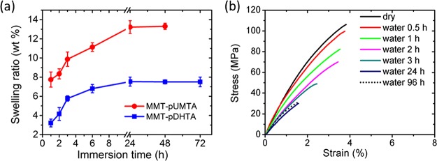
We also investigated the water absorption kinetics and the corresponding change of the mechanical properties of the composites. Figure 7a shows the swelling ratio of MMT–pUMTA and MMT–pDHTA in water as a function of immersion time. For both MMT–pUMTA and MMT–pDHTA, the swelling ratio gradually increases with time, until it saturates at 13 and 8 wt %, respectively, after 24 h. Although the composites mainly consist of originally hydrophilic MMT (∼80 wt % for MMT–pUMTA and ∼70 wt % for MMT–pDHTA), the equilibrium swelling ratio of the composites is surprisingly low. This can be ascribed to the high hydrophobicity of the modified MMT surface owing to the long alkyl chains in the repeat units of pUMTA and pDHTA. The swelling ratio of MMT–pUMTA is higher than that of MMT–pDHTA over the whole range of immersion time, presumably because the hydrophobicity of pUMTA, which had a shorter alkyl chain, was lower than that of pDHTA, which had a longer alkyl chain. To confirm the effects of hydrophobicity of the composite, we further analyzed the change of mechanical properties upon water absorption.
Figure 7.
(a) Swelling ratio of MMT–pUMTA and MMT–pDHTA in water. The error bars represent the standard deviation. (b) Stress–strain curves of MMT–pDHTA in the dry state and after immersion in water for different times.
The tensile properties were investigated for MMT–pDHTA films after immersion in water as well as in a dry state. As shown in Figure 7b and summarized in Table S3, the dry-state Young’s modulus, tensile strength, and tensile strain were 5.5 ± 0.3 GPa, 96.9 ± 2.9 MPa, and 3.5 ± 0.6%, respectively. The observed tensile strength of MMT–pDHTA films was similar to that of natural nacre (80–135 MPa).42,43 Generally, the high mechanical performance of nacre-like composites is attributed to the high loading of inorganic substances, layered structure, and strong organic–inorganic interfacial interaction.7,44,45 MMT–pDHTA satisfies these criteria: it possesses a high MMT content (70 wt %), layered structure, and strong ionic interaction between the quaternary ammonium cation of the polymer and the anionic MMT surface. When immersed in water, the mechanical properties of MMT–pDHTA deteriorated over time owing to the moisture-induced reduction of the polymer–clay interaction.46 However, MMT–pDHTA exhibited a relatively high mechanical strength and hardness even after reaching equilibrium swelling under water. After water immersion for 24 h, the Young’s modulus, tensile strength, and tensile strain reached 2.9 ± 0.3 GPa, 29.6 ± 1.7 MPa, and 1.4 ± 0.1%, respectively, which did not change any further after immersion for up to 96 h (Table S3). This stability clearly shows the excellent water resistance of MMT–pDHTA, allowing its use even in water.
The swelling behavior and mechanical properties of the composite in other solvents were also investigated. Figure S7a shows the swelling ratio of MMT–pDHTA in methanol, acetone, and chloroform as a function of time. The difference of the swelling ratio in different solvents can be attributed to the affinity between pDHTA and the solvent. After immersion for 24 h in these solvents, the mechanical properties of the samples did deteriorate compared to the dry state, but the ultimate stress was maintained at above 5 MPa (Figure S7b). As mentioned above, owing to the covalent bonding between adjacent clay platelets by the polymerization of surface modifiers, the robust ionic interaction at the interface, and the extremely high loading of clay, the composite in this study maintains its mechanical properties in various solvents.
Conclusions
In summary, we fabricated water-resistant nacre-like composite films in which the MMT platelets were covered and connected by hydrophobic polymer chains. We first modified MMT with quaternary ammonium salts having long alkyl chains with a methacryloyl group at the end, to endow both reactivity and hydrophobicity. The high aspect ratio of MMT and the reaction between surface modifiers contributed to the self-alignment of the MMT platelets into the nacre-like structure during in situ polymerization. The resulting composite film had an excellent mechanical strength similar to natural nacre. In addition, although the composite film was mostly made up of originally hydrophilic MMT platelets, it exhibited a consistently high mechanical performance even after reaching equilibrium swelling in water. It also showed shape stability in various organic solvents including methanol, acetone, and chloroform. These superior properties of the composites are probably because of the robust interaction at the interface, tight binding between MMT platelets by the polymerized surface modifiers, and high loading of clay (70–80 wt %). Given the high mechanical performance, water-resistant property, and shape stability in organic solvents, these composite films can be used in many practical applications.
Experimental Section
Details on the materials and synthesis of the surface-modifying agents, UMTA and DHTA, are presented in the Supporting Information.
Surface Modification of MMT
A typical procedure for the ion-exchange reaction was employed for the surface modification of MMT.24 First, 4 g of MMT was added to 300 mL of deionized water and stirred vigorously for 2 days to obtain a dispersion. A solution of a surface-modifying agent (UMTA or DHTA, 6.0 × 10⁻³ mol) in 200 mL of deionized water was added to the dispersion with continuous stirring. The mixture was stirred for an additional day. The white precipitate formed in this step was isolated by filtration, followed by dispersion in 500 mL of water by stirring for 30 min. This process was repeated thrice to remove the excess surface modifier. The washed precipitate was filtered and dried overnight under vacuum at 40 °C. The product was then ground to yield a fine powder and stored in a desiccator. We, hereafter, refer to MMT surface-modified with UMTA and DHTA as “MMT–UMTA” and “MMT–DHTA”, respectively.
Fabrication of Composite Films
A 5 wt % dispersion of the surface-modified clay (MMT–UMTA or MMT–DHTA) was obtained by vigorous stirring in DMA for 3 h. To this dispersion, 0.5 wt % of 2,2-dimethoxy-2-phenylacetophenone was added and stirred for another 10 min. The mixture was then transferred to a Teflon Petri dish and irradiated with a UV light (λ = 400–315 nm) from the top for 24 h, resulting in gel-like deposits (MMT–pUMTA_gel and MMT–pDHTA_gel, respectively). The Teflon dish was then heated on a hot plate (40–100 °C, nitrogen atmosphere, 24 h) to remove the solvent, following which the film-like product was peeled off from the Petri dish. The film was washed by immersion in methanol for 24 h followed by drying at 60 °C for 5 h. The resulting stiff and translucent composite films made from MMT–UMTA and MMT–DHTA were labeled “MMT–pUMTA” and “MMT–pDHTA”, respectively.
Reverse Ion Exchange of Composite Films
The organic component in MMT–pUMTA and MMT–pDHTA was separated from the clay by reverse ion-exchange reaction.38−40 In 40 mL of dimethyl sulfoxide, 500 mg of the composite film and 2 g of LiBr were mixed. The mixture was stirred vigorously for 4 days at 60 °C. The resultant solution was centrifuged at 5000 rpm for 10 min, resulting in a transparent supernatant and a brownish-yellow sediment. The supernatant was collected by decantation and poured into 400 mL of tetrahydrofuran to precipitate the organic component. This organic component was then filtered with a membrane filter (pore size: 0.45 μm), redissolved in methanol, and recovered by drying at 40 °C. The organic component was characterized by 1H NMR in deuterated water.
Synthesis of Homopolymers
As a reference, homopolymers of UMTA and DHTA, namely hpUMTA and hpDHTA, were synthesized. For the synthesis of hpUMTA, a mixture of UMTA (500 mg), 2,2-dimethoxy-2-phenylacetophenone (10 mg), and methanol (10 mL) was irradiated by UV light (λ = 400–315 nm) overnight. After the reaction, the mixture was cast, washed with acetone, and dried at 60 °C in a vacuum oven. hpDHTA was synthesized by a similar method.
Solvent Absorbency Test of Composite Films
Water, methanol, acetone, and chloroform were used as the solvents. The weight of the composite film was measured after immersion into the solvents for predetermined periods. The swelling ratio was then calculated as
| 2 |
where Wd and Ws are the weights of the composite before and after swelling by the solvent, respectively.
Analyses
1H NMR spectra were acquired using a JEOL JNM-AL 400 spectrometer (400 MHz, JEOL) in deuterated solvents at 20 °C. TGA was carried out on a Rigaku TG 8120 instrument under air atmosphere at a flow rate and heating rate of 50 mL min–1 and 10 K min–1, respectively. 1D XRD profiles were obtained using a Rigaku RINT-2100 diffractometer, with a Cu Kα radiation (wavelength λ = 0.15418 nm) and a scan speed of 2° min–1. The d spacing corresponding to the diffraction angle 2θ was calculated by the formula d = λ/(2 sin θ). Two-dimensional XRD images were acquired using the SAXSpoint 2.0 (Anton Paar, Austria) equipped with a 2D hybrid-pixel detector (EIGER R, Dectris, Switzerland), again with the Cu Kα radiation. The film samples cut into rectangular pieces were irradiated in a direction parallel to the film plane. ATR–FTIR spectra were obtained with a Thermo Scientific Nicolet iS10 FTIR spectrometer equipped with the Thermo Scientific Smart iTR with a diamond crystal. SEM images were obtained by using the JCM-6000Plus (JEOL) microscope. All samples were sputtered with a thin layer of platinum in an electric field of 30 mA for 30 s under vacuum (<5 Pa) with a JFC-1600 Auto Fine Coater (JEOL) instrument before the observations. Tensile tests were carried out using the Shimadzu EZ-L 200N tester. The samples were cut into rectangles (3 × 21 mm) and stored in a desiccator (<20% of RH) for over 3 days or immersed in water for the required time. A strain rate and gauge length of 1 mm min–1 and 7 mm, respectively, were used under ambient conditions. The thickness of the specimen was measured with a constant-pressure thickness gauge in the range of 75–100 μm. For each sample and condition, 4–7 pieces were tested to confirm the accuracy of the result.
Acknowledgments
2D XRD measurements were performed using SAXSpoint 2.0 (Anton Paar, Austria) provided for the user program at the Institute for Solid State Physics at The University of Tokyo in Japan.
Supporting Information Available
The Supporting Information is available free of charge on the ACS Publications website at DOI: 10.1021/acsomega.7b01606.
Materials; synthesis and 1H NMR characterization of UMTA and DHTA, ATR–FTIR peaks of MMT, MMT–UMTA, and MMT–DHTA as well as those assignments with chemical groups; photographs showing the dispersion state of surface-modified clay in DMA, gel-like deposit, and composite film; 1H NMR spectra of surface modifier, cleaved organic molecules after reverse ion exchange, and homopolymers of surface modifier; d spacing trace of surface-modified clays, gel-like deposits, and composite films measured by 1D XRD; mechanical property of MMT–pDHTA in the dry state and after immersion in water for different times; and swelling ratio in organic solvents and corresponding mechanical properties of MMT–pDHTA (PDF)
The authors declare no competing financial interest.
Supplementary Material
References
- Barthelat F. Biomimetics for next generation materials. Philos. Trans. R. Soc., A 2007, 365, 2907–2919. 10.1098/rsta.2007.0006. [DOI] [PubMed] [Google Scholar]
- Podsiadlo P.; Liu Z.; Paterson D.; Messersmith P. B.; Kotov N. A. Fusion of Seashell Nacre and Marine Bioadhesive Analogs: High-Strength Nanocomposite by Layer-by-Layer Assembly of Clay and L-3,4-Dihydroxyphenylalanine Polymer. Adv. Mater. 2007, 19, 949–955. 10.1002/adma.200602706. [DOI] [Google Scholar]
- Podsiadlo P.; Kaushik A. K.; Shim B. S.; Agarwal A.; Tang Z.; Waas A. M.; Arruda E. M.; Kotov N. A. Can nature’s design be improved upon? High strength, transparent nacre-like nanocomposites with double network of sacrificial cross links. J. Phys. Chem. B 2008, 112, 14359–14363. 10.1021/jp801492n. [DOI] [PubMed] [Google Scholar]
- Jackson A. P.; Vincent J. F. V.; Turner R. M. The mechanical design of nacre. Proc. R. Soc. London, Ser. B 1988, 234, 415–440. 10.1098/rspb.1988.0056. [DOI] [Google Scholar]
- Mayer G. Rigid biological systems as models for synthetic composites. Science 2005, 310, 1144–1147. 10.1126/science.1116994. [DOI] [PubMed] [Google Scholar]
- Tang Z.; Kotov N. A.; Magonov S.; Ozturk B. Nanostructured artificial nacre. Nat. Mater. 2003, 2, 413–418. 10.1038/nmat906. [DOI] [PubMed] [Google Scholar]
- Podsiadlo P.; Kaushik A. K.; Arruda E. M.; Waas A. M.; Shim B. S.; Xu J.; Nandivada H.; Pumplin B. G.; Lahann J.; Ramamoorthy A.; Kotov N. A. Ultrastrong and stiff layered polymer nanocomposites. Science 2007, 318, 80–83. 10.1126/science.1143176. [DOI] [PubMed] [Google Scholar]
- Das P.; Malho J.-M.; Rahimi K.; Schacher F. H.; Wang B.; Demco D. E.; Walther A. Nacre-mimetics with synthetic nanoclays up to ultrahigh aspect ratios. Nat. Commun. 2015, 6, 5967. 10.1038/ncomms6967. [DOI] [PubMed] [Google Scholar]
- Wang J.; Cheng Q.; Lin L.; Jiang L. Synergistic toughening of bioinspired poly(vinyl alcohol)–clay–nanofibrillar cellulose artificial nacre. ACS Nano 2014, 8, 2739–2745. 10.1021/nn406428n. [DOI] [PubMed] [Google Scholar]
- Walther A.; Bjurhager I.; Malho J.-M.; Pere J.; Ruokolainen J.; Berglund L. A.; Ikkala O. Large-area, lightweight and thick biomimetic composites with superior material properties via fast, economic, and green pathways. Nano Lett. 2010, 10, 2742–2748. 10.1021/nl1003224. [DOI] [PubMed] [Google Scholar]
- Wan S.; Peng J.; Jiang L.; Cheng Q. Bioinspired Graphene-Based Nanocomposites and Their Application in Flexible Energy Devices. Adv. Mater. 2016, 28, 7862–7898. 10.1002/adma.201601934. [DOI] [PubMed] [Google Scholar]
- Cui W.; Li M.; Liu J.; Wang B.; Zhang C.; Jiang L.; Cheng Q. A Strong Integrated Strength and Toughness Artificial Nacre Based on Dopamine Cross-Linked Graphene Oxide. ACS Nano 2014, 8, 9511–9517. 10.1021/nn503755c. [DOI] [PubMed] [Google Scholar]
- El-Kady M. F.; Strong V.; Dubin S.; Kaner R. B. Laser Scribing of High-Performance and Flexible Graphene-Based Electrochemical Capacitors. Science 2012, 335, 1326–1330. 10.1126/science.1216744. [DOI] [PubMed] [Google Scholar]
- Shahzadi K.; Mohsin I.; Wu L.; Ge X.; Jiang Y.; Li H.; Mu X. Bio-Based Artificial Nacre with Excellent Mechanical and Barrier Properties Realized by a Facile In Situ Reduction and Cross-Linking Reaction. ACS Nano 2017, 11, 325–334. 10.1021/acsnano.6b05780. [DOI] [PubMed] [Google Scholar]
- Bonderer L. J.; Studart A. R.; Gauckler L. J. Bioinspired design and assembly of platelet reinforced polymer films. Science 2008, 319, 1069–1073. 10.1126/science.1148726. [DOI] [PubMed] [Google Scholar]
- Wang J.; Qiao J.; Wang J.; Zhu Y.; Jiang L. Bioinspired Hierarchical Alumina–Graphene Oxide–Poly(vinyl alcohol) Artificial Nacre with Optimized Strength and Toughness. ACS Appl. Mater. Interfaces 2015, 7, 9281–9286. 10.1021/acsami.5b02194. [DOI] [PubMed] [Google Scholar]
- Sehaqui H.; Kochumalayil J.; Liu A.; Zimmermann T.; Berglund L. A. Multifunctional nanoclay hybrids of high toughness, thermal, and barrier performances. ACS Appl. Mater. Interfaces 2013, 5, 7613–7620. 10.1021/am401928d. [DOI] [PubMed] [Google Scholar]
- Das P.; Walther A. Ionic supramolecular bonds preserve mechanical properties and enable synergetic performance at high humidity in water-borne, self-assembled nacre-mimetics. Nanoscale 2013, 5, 9348–9356. 10.1039/c3nr02983b. [DOI] [PubMed] [Google Scholar]
- Kochumalayil J. J.; Morimune S.; Nishino T.; Ikkala O.; Walther A.; Berglund L. A. Nacre-mimetic clay/xyloglucan bionanocomposites: a chemical modification route for hygromechanical performance at high humidity. Biomacromolecules 2013, 14, 3842–3849. 10.1021/bm400883e. [DOI] [PubMed] [Google Scholar]
- Verho T.; Karesoja M.; Das P.; Martikainen L.; Lund R.; Alegría A.; Walther A.; Ikkala O. Hydration and Dynamic State of Nanoconfined Polymer Layers Govern Toughness in Nacre-mimetic Nanocomposites. Adv. Mater. 2013, 25, 5055–5059. 10.1002/adma.201301881. [DOI] [PubMed] [Google Scholar]
- Yao K.; Huang S.; Tang H.; Xu Y.; Buntkowsky G.; Berglund L. A.; Zhou Q. Bioinspired Interface Engineering for Moisture Resistance in Nacre-Mimetic Cellulose Nanofibrils/Clay Nanocomposites. ACS Appl. Mater. Interfaces 2017, 9, 20169–20178. 10.1021/acsami.7b02177. [DOI] [PubMed] [Google Scholar]
- Wu Q.; Guo D.; Zhang Y.; Zhao H.; Chen D.; Nai J.; Liang J.; Li X.; Sun N.; Guo L. Facile and Universal Superhydrophobic Modification to Fabricate Waterborne, Multifunctional Nacre-Mimetic Films with Excellent Stability. ACS Appl. Mater. Interfaces 2014, 6, 20597–20602. 10.1021/am505265x. [DOI] [PubMed] [Google Scholar]
- Das P.; Thomas H.; Moeller M.; Walther A. Large-scale, thick, self-assembled, nacre-mimetic brick-walls as fire barrier coatings on textiles. Sci. Rep. 2017, 7, 39910. 10.1038/srep39910. [DOI] [PMC free article] [PubMed] [Google Scholar]
- Chiu C.-W.; Huang T.-K.; Wang Y.-C.; Alamani B. G.; Lin J.-J. Intercalation strategies in clay/polymer hybrids. Prog. Polym. Sci. 2014, 39, 443–485. 10.1016/j.progpolymsci.2013.07.002. [DOI] [Google Scholar]
- Biasci L.; Aglietto M.; Ruggeri G.; Ciardelli F. Functionalization of montmorillonite by methyl methacrylate polymers containing side-chain ammonium cations. Polymer 1994, 35, 3296–3304. 10.1016/0032-3861(94)90138-4. [DOI] [Google Scholar]
- Xi Y.; Frost R. L.; He H. Modification of the surfaces of Wyoming montmorillonite by the cationic surfactants alkyl trimethyl, dialkyl dimethyl, and trialkyl methyl ammonium bromides. J. Colloid Interface Sci. 2007, 305, 150–158. 10.1016/j.jcis.2006.09.033. [DOI] [PubMed] [Google Scholar]
- Samakande A.; Hartmann P. C.; Cloete V.; Sanderson R. D. Use of acrylic based surfmers for the preparation of exfoliated polystyrene–clay nanocomposites. Polymer 2007, 48, 1490–1499. 10.1016/j.polymer.2006.07.072. [DOI] [Google Scholar]
- Zhou L.; Chen H.; Jiang X.; Lu F.; Zhou Y.; Yin W.; Ji X. Modification of montmorillonite surfaces using a novel class of cationic gemini surfactants. J. Colloid Interface Sci. 2009, 332, 16–21. 10.1016/j.jcis.2008.12.051. [DOI] [PubMed] [Google Scholar]
- Lagaly G. Interaction of alkylamines with different types of layered compounds. Solid State Ionics 1986, 22, 43–51. 10.1016/0167-2738(86)90057-3. [DOI] [Google Scholar]
- Sadhu S.; Bhowmick A. K. Preparation and properties of styrene–butadiene rubber based nanocomposites: the influence of the structural and processing parameters. J. Appl. Polym. Sci. 2004, 92, 698–709. 10.1002/app.13673. [DOI] [Google Scholar]
- Fu X.; Qutubuddin S. Polymer–clay nanocomposites: exfoliation of organophilic montmorillonite nanolayers in polystyrene. Polymer 2001, 42, 807–813. 10.1016/s0032-3861(00)00385-2. [DOI] [Google Scholar]
- Zhang W. A.; Chen D. Z.; Xu H. Y.; Shen X. F.; Fang Y. E. Influence of four different types of organophilic clay on the morphology and thermal properties of polystyrene/clay nanocomposites prepared by using the γ-ray irradiation technique. Eur. Polym. J. 2003, 39, 2323–2328. 10.1016/j.eurpolymj.2003.08.006. [DOI] [Google Scholar]
- Wang M.; Zhao F.; Guo Z.; Dong S. Poly(vinylidene fluoride-hexafluoropropylene)/organo-montmorillonite clays nanocomposite lithium polymer electrolytes. Electrochim. Acta 2004, 49, 3595–3602. 10.1016/j.electacta.2004.03.028. [DOI] [Google Scholar]
- Kou M. R. S.; Mendioroz S.; Guijarro M. I. A thermal study of Zr-pillared montmorillonite. Thermochim. Acta 1998, 323, 145–157. 10.1016/s0040-6031(98)00540-1. [DOI] [Google Scholar]
- Yuan P.; Annabi-Bergaya F.; Tao Q.; Fan M.; Liu Z.; Zhu J.; He H.; Chen T. A combined study by XRD, FTIR, TG and HRTEM on the structure of delaminated Fe-intercalated/pillared clay. J. Colloid Interface Sci. 2008, 324, 142–149. 10.1016/j.jcis.2008.04.076. [DOI] [PubMed] [Google Scholar]
- Zhou J.; Wu P.; Dang Z.; Zhu N.; Li P.; Wu J.; Wang X. Polymeric Fe/Zr pillared montmorillonite for the removal of Cr(VI) from aqueous solutions. Chem. Eng. J. 2010, 162, 1035–1044. 10.1016/j.cej.2010.07.016. [DOI] [Google Scholar]
- Lee W.-F.; Chen Y.-C. Preparation of reactive mineral powders used for poly(sodium acrylate) composite superabsorbents. J. Appl. Polym. Sci. 2005, 97, 855–861. 10.1002/app.21812. [DOI] [Google Scholar]
- Messersmith P. B.; Giannelis E. P. Synthesis and barrier properties of poly(ε-caprolactone)-layered silicate nanocomposites. J. Polym. Sci., Part A: Polym. Chem. 1995, 33, 1047–1057. 10.1002/pola.1995.080330707. [DOI] [Google Scholar]
- Meier L. P.; Shelden R. A.; Caseri W. R.; Suter U. W. Polymerization of styrene with initiator ionically bound to high surface area mica: grafting via an unexpected mechanism. Macromolecules 1994, 27, 1637–1642. 10.1021/ma00084a054. [DOI] [Google Scholar]
- Choi Y. S.; Choi M. H.; Wang K. H.; Kim S. O.; Kim Y. K.; Chung I. J. Synthesis of exfoliated PMMA/Na-MMT nanocomposites via soap-free emulsion polymerization. Macromolecules 2001, 34, 8978–8985. 10.1021/ma0106494. [DOI] [Google Scholar]
- Vaia R. A.; Teukolsky R. K.; Giannelis E. P. Interlayer structure and molecular environment of alkylammonium layered silicates. Chem. Mater. 1994, 6, 1017–1022. 10.1021/cm00043a025. [DOI] [Google Scholar]
- Barthelat F.; Li C.-M.; Comi C.; Espinosa H. D. Mechanical properties of nacre constituents and their impact on mechanical performance. J. Mater. Res. 2006, 21, 1977–1986. 10.1557/jmr.2006.0239. [DOI] [Google Scholar]
- Barthelat F. Nacre from mollusk shells: a model for high-performance structural materials. Bioinspiration Biomimetics 2010, 5, 035001. 10.1088/1748-3182/5/3/035001. [DOI] [PubMed] [Google Scholar]
- Walther A.; Bjurhager I.; Malho J.-M.; Ruokolainen J.; Berglund L.; Ikkala O. Supramolecular Control of Stiffness and Strength in Lightweight High-Performance Nacre-Mimetic Paper with Fire-Shielding Properties. Angew. Chem., Int. Ed. 2010, 49, 6448–6453. 10.1002/anie.201001577. [DOI] [PubMed] [Google Scholar]
- Li Y.-Q.; Yu T.; Yang T.-Y.; Zheng L.-X.; Liao K. Bio-inspired nacre-like composite films based on graphene with superior mechanical, electrical, and biocompatible properties. Adv. Mater. 2012, 24, 3426–3431. 10.1002/adma.201200452. [DOI] [PubMed] [Google Scholar]
- Selzer R.; Friedrich K. Mechanical properties and failure behaviour of carbon fibre-reinforced polymer composites under the influence of moisture. Composites, Part A 1997, 28, 595–604. 10.1016/s1359-835x(96)00154-6. [DOI] [Google Scholar]
Associated Data
This section collects any data citations, data availability statements, or supplementary materials included in this article.


