Abstract
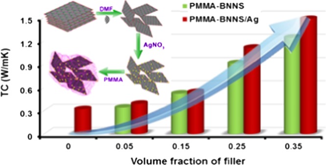
High-thermal-conductivity and low-dielectric-loss polymer nanocomposites have gained tremendous attention in microelectronics technology. Against this background, the present study deals with the development of a high-thermal-conductivity, low-dielectric-constant, and low-loss polymer nanocomposite based on silver nanoparticle (AgNP)-decorated boron nitride nanosheets (BNNSs) as the filler in poly(methyl methacrylate) (PMMA) matrix. The nanocomposites were prepared through a facile solution-blending process. Elemental mapping of the prepared nanocomposite indicates the uniform distribution of filler particle in PMMA matrix. An impressive high-thermal conductivity (TC) enhancement of around 363% was achieved for nanocomposite of 0.35 Vf of hybrid filler (1.48 W/m K) compared to pristine PMMA (0.32 W/m K). The addition of AgNP reduces the thermal contact resistance (Rc) by bridging individual BNNS, thereby improving thermal transport. Measured TC values were fitted with a theoretical model that showed good agreement. Dielectric measurements performed at radiofrequencies and microwave frequencies revealed that the nanocomposites show a low dielectric constant (<5), low loss (10–2), and very low alternating current conductivity (10–7 S/cm). The results suggest that silver-decorated BNNS is a promising hybrid filler for effective thermal management.
1. Introduction
Breathtaking developments happening in consumer electronics and personal computers have been demanding miniaturized components with better speed and performance. Managing the circuit heat dissipation is a vital issue that needs to be addressed urgently to improve the reliability and performances of devices. Over the last few decades, polymers have gained pronounced attention as substrates, owing to their excellent design freedom, light weight, and low cost.1−3 But, they have genuine drawbacks like high coefficient of thermal expansion (CTE, 40–200 ppm/K) and low thermal conductivity (TC, <0.5 W/m K),4 which debilitate their wide range of electronic applications. The low thermal conductivity of the substrate leads to inadequate heat dissipation, which adversely affects the performance and lifetime of circuits. Here, the low thermal conductivity results from high-thermal interface resistance caused by the amorphous arrangement of polymer chains.5 Hence, reduction in thermal stresses and improvement in heat removal are critical concerns in the current electronic substrate and packaging applications.6−9 Although the prime concern is to improve the thermal conductivity of polymeric materials, desired electrical resistivity and mechanical properties should also not be compromised.
On this aspect, the thermal conductivity of polymers can be enhanced by incorporating high-thermal-conductivity fillers, such as metals and carbonaceous and ceramic materials into the matrix. The properties of polymer nanocomposites are governed by certain factors such as chemical composition, shape, and orientation of filler in the polymer matrix. The influence of the particle size and interaction of fillers in the polymer matrix on the mechanical, electrical, and thermal properties of nanocomposites was well studied.10,11 Even though carbon-based materials (carbon nanotube (CNT), graphene)12 and metals (silver, nickel)13 can increase the thermal conductivity, the high electrical conductivity14 of these composites will generate electric leakage in the substrate, which tends to limit their practical use in electronic packaging systems. On the other hand, thermally conducting yet electrically insulating ceramic materials, such as oxides [alumina (Al2O3),15 beryllium oxide (BeO),14 zinc oxide (ZnO)16], nitrides [aluminum nitride (AlN),17−21 boron nitride (BN),22,23 silicon nitride (Si3N4)] and a few carbides [silicon carbide (SiC)],24 are good choices for thermal management applications. Among these, hexagonal boron nitride (h-BN) took a lead role due to its excellent properties like large surface area, high-thermal transport, and chemical inertness.25−27 It is also a good electrical insulator having a wide band gap of ∼6 eV.28,29 Besides, the thermal conductivity of bulk h-BN is found to be as high as 400 W/m K at room temperature.30,31 A theoretical estimation revealed that the value of thermal conductivity of BN nanoribbons can reach up to 3000 W/m K.32 Contrast to other nanofillers, two-dimensional h-BN nanosheets (BNNSs) with exposed (002) plane can enhance the phonon transfer, thereby increasing the thermal conductivity.22 Moreover, the aspect ratio of BNNS is large enough to obtain good thermal transport even at low filler loading.5,33,34 Incorporating h-BN as nanofiller, thermal conductivity improvement of several polymeric systems (epoxy,35−39 poly(methyl methacrylate) (PMMA),7,40,41 poly(vinyl butyral)1) has been reported earlier.42
Nowadays, apart from the use of single filler, hybrid fillers are also successfully used to improve the thermal conductivity of polymers. Recently, Wang et al. have reported nanosilver-decorated BNNS as a hybrid filler to improve the thermal conductivity of epoxy-based nanocomposites.35,43 In 2016, Xia et al. reported natural fiber–h-BN hybrid filler-reinforced epoxy composites with improved thermal and mechanical properties.44 By virtue of bioinspired engineering, Yao et al. developed poly(vinyl alcohol)–paper composite with enhanced thermal conductivity by utilizing BNNS/AgNP/SiC nanowire as the hybrid filler.45 High-performance composites with high-thermal conductivity, good flame retardancy, and low dielectric loss were fabricated using hybrid fillers consisting of aluminum nitride and multiwalled carbon nanotubes in cyanate ester matrix.46 The improved performance of hybrid filler is arguably due to its synergetic effect with tuning compatibility and enhanced connectivity obtained from the corresponding fillers.47
In the present work, silver nanoparticle-decorated BNNS were taken as the hybrid filler to improve the thermal conductivity of PMMA nanocomposites, while maintaining their high electrical resistivity. PMMA is a transparent thermoplastic polymer, and its ceramic composite was extensively studied for electronic applications.48−50 Here, we have systematically compared the properties of PMMA–BNNS nanocomposite phases (abbreviated as PMMA–BX) with PMMA–Ag-decorated BNNS nanocomposites (abbreviated as PMMA–BAX). Interestingly, PMMA–BAX nanocomposites show high-thermal conductivity compared to neat PMMA as well as PMMA–BX-based composites. Furthermore, the developed PMMA–BAX nanocomposite shows low dielectric constant and appreciably low dielectric loss with improved mechanical strength. The results reveal that the concentration of silver nanoparticles on BNNS can be very low enough to form conducting percolation channels. At the same time, it facilitates connections between the exfoliated BNNS, whereby the mechanism of transfer of phonons gets intensified. Thus, the PMMA–BAX nanocomposite is suggested as an attractive candidate for thermal management applications in the electronic packaging industry.
2. Results and Discussion
2.1. Structural Characterization of BNNS and BNNS/AgNP
The crystal structure of boron nitride nanosheets (BNNSs) is very much similar to that of graphene, which consists of layered structure comprising a network of (BN)3 rings that were held together by van der Waals bonds. Crystallinity, phase purity, and deposition of AgNP over BNNS were confirmed by X-ray diffraction (XRD) analysis. Figure 1 shows the XRD patterns of liquid-exfoliated BNNS and BNNS/AgNP. It is evident from the pattern that BNNS are completely phase-pure and no impurity phases were present. Both BNNS and BNNS/AgNP show identical diffraction peaks corresponding to the (002), (100), (101), (102), (004), (104), (110), and (112) crystallographic planes of hexagonal boron nitride. All peaks could be well indexed using standard ICDD pattern of h-BN (00-034-0421), and it belongs to the P63/mmc space group. The XRD pattern of hybrid filler shows a characteristic peak (111) (represented by an asterisk) originated from the silver nanoparticles, which indicates the presence of silver nanoparticles over BNNS.
Figure 1.
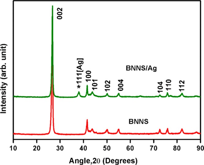
XRD patterns of BNNS and BNNS/AgNP.
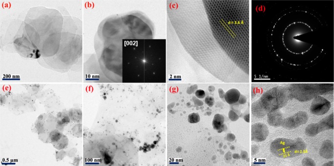
Surface morphologies of BNNS and BNNS/AgNP were studied using transmission electron microscopy (TEM) and atomic force microscopy (AFM) techniques. The exfoliated BNNS comprise isolated flat nanosheets, as shown in Figure 2a,b as low-magnification TEM images. Figure 2c,d shows a high-resolution micrograph and selected area electron diffraction (SAED) pattern of BNNS, respectively. As seen from Figure 2c, the lattice fringes were clearly visible, indicating the highly crystalline nature of exfoliated BNNS. The d-spacing of BNNS was calculated from these lattice fringes as 3.6 Å, corresponding to the reflections from (002) plane. The representative fast Fourier transform (FFT) pattern is shown in the inset of Figure 2b, which reaffirms that the diffraction was from (002) plane. Figure 2d is the selected area electron diffraction (SAED) pattern, which reveals that BNNS hold a sixfold symmetry that was not impaired during exfoliation. Moreover, TEM images of silver nanoparticle-decorated BNNS are shown in Figure 2e–h. From these images, one can observe that no individual silver nanoparticle was found beside BNNS, which confirms that the silver nanoparticles were more or less uniformly distributed over BNNS. Figure 2h shows that the interplanar spacing of the silver nanoparticle lattice is about 2.3 Å, which well matched with the d-value of the (111) plane of silver.
Figure 2.
(a, b) Low-magnification TEM images of BNNS, and (inset to (b)) FFT patterns of the corresponding image. (c) High-resolution TEM (HRTEM) image. (d) SAED pattern. (e–h) Low- and high-magnification TEM images of BNNS/AgNP.
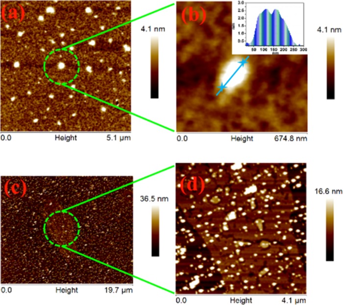
The lateral size (edge-to-edge) and sheet thickness of BNNS were calculated from representative atomic force micrography images. Figures 3a and 3b show the topographic images of exfoliated BNNS, suggesting that the lateral size comes around 190 nm. The thicknesses were estimated from the height profile given as inset to Figure 3b, which is of the order of 2.4 nm, corresponding to about five to eight nanolayers.51Figures 3c and 3d represent the AFM images of hybrid filler, AgNP/BNNS, and further confirm the uniform distribution of AgNP all over BNNS.
Figure 3.
(a, b) AFM images of exfoliated BNNS; (inset to (b)) height profile. (c, d) AFM images of silver nanoparticle-decorated BNNS (BNNS/AgNP).
2.2. Thermal Conductivity of PMMA–BAX and PMMA–BX
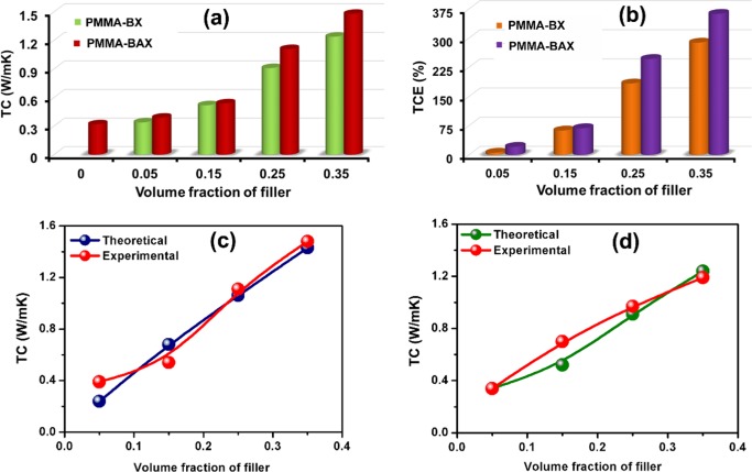
To evaluate their potential application in electronic packaging industry, thermal conductivity analysis of the composites was carried out. Thermal conductivity and thermal conductivity enhancement (TCE) of PMMA–BX and PMMA–BAX with various filler loadings are shown in Figure 4a,b, respectively. From Figure 4a, it is evident that pure PMMA possesses a low thermal conductivity of around 0.32 W/m K at room temperature, mainly due to its amorphous nature. After the addition of fillers to pure polymer, the thermal conductivity increased as a function of filler loading. It is interesting to note from Figure 4a that the thermal conductivity of PMMA–B35 reaches a maximum value of 1.2 W/m K, whereas the hybrid filler (PMMA–BA35) composites are found to offer better thermal conductivity (1.48 W/m K) at room temperature. In general, the thermal conductivity of a material can be enhanced by suppressing phonon scattering through strong interfacial interactions.43 The underlying mechanism behind the high-thermal conductivity achieved by the hybrid filler (PMMA–BA35) compared to the PMMA–BX composite alone (PMMA–B35) is the capability of silver nanoparticles to form bridges between the exfoliated BNNS providing easy thermal conducting networks. Through this conducting path, transfer of phonons is enhanced and consequently thermal transport resistance gets minimized. However, there is no notable difference in the thermal conductivities of PMMA–BX and PMMA–BAX at low Vf. This is because at lower Vf the primary component in the nanocomposite is the polymer matrix. Hence, the filler is completely surrounded by PMMA and thus the silver nanoparticles cannot perform effectively to form bridging between BNNS.35 After reaching a critical limit, say 0.25 Vf, there is a significant improvement in the TC of the PMMA–BAX composite compared to PMMA–BX, indicating the effective connection of BNNS through AgNP. From the above results, it can be concluded that the hybrid filler PMMA–BAX is more capable of heat dissipation compared to the PMMA–BX composites in electronic packaging.
Figure 4.
(a, b) Thermal conductivity (TC) and thermal conductivity enhancement (TCE) of nanocomposites. (c, d) Measured and calculated thermal conductivity of PMMA–BAX and PMMA–BX nanocomposites respectively.
A quantitative analysis of the improvement in TC of the composites was conducted by calculating thermal conductivity enhancement (TCE) by the formula
| 1 |
where κcomp is the TC of the composite and κPMMA is the TC of pristine PMMA. Figure 4b shows TCE as a function of Vf for both PMMA–BAX and PMMA–BX at room temperature. As it is evident from Figure 4b, up to 0.15 Vf, there was not much improvement in TCE compared to both PMMA–BAX and PMMA–BX. However, above the critical limit of 0.25 Vf, TCE of PMMA–BAX shows an appreciable improvement compared to that of PMMA–BX. For instance, with 0.35 Vf, the TCE for the PMMA–BAX nanocomposite is 363%, whereas that of PMMA–BX is almost 280% only. The high value of TCE in the PMMA–BAX nanocomposite suggests that the incorporation of AgNP can effectively improve the thermal transport through BNNS.
We have attempted to compare the apparent thermal conductivity of composites with a suitable theoretical model. Several research groups simulated thermal boundaries within nanofillers and theoretically calculated thermal contact resistance between filler and polymer matrix.52−54 In the present work, a physical model proposed by Foygel et al. was applied to calculate TC of polymer nanocomposites. The Foygel physical model mainly considered the distribution of fillers and percolation networks in the polymer matrix.55 Using the following equation, thermal conductivity of polymer nanocomposites can be theoretically calculated as
| 2 |
where K0 is a pre-exponential factor depending on the effective thermal conductivity of the filler networks, VC is the critical volume fraction at the thermal percolation threshold, and t(α) is a conductivity exponent dependent on the aspect ratio (α) of BNNS. In the present study, the aspect ratio of BNNS was estimated mainly from AFM results. Using the above equation, TC of nanocomposites was calculated and fitted with experimental data with fitting parameters K0 and t(α), as shown in Figure 4c,d. For both PMMA–BX and PMMA–BAX composites, the fit follows most of the experimental values, especially in high filler loadings, corroborating the good match between experimental and theoretical results. The K0 was estimated to be 2.26 W/m K for PMMA–BX and 3.54 W/m K for PMMA–BAX nanocomposites. Thermal contact resistance (Rc) can be calculated from the following equation with the aid of K0 and t(α) as
| 3 |
The value of Rc calculated for BNNS filler in the PMMA–BX composite was 1.74 × 10⁸ K/W, whereas that for BNNS/AgNP hybrid filler in the PMMA–BAX composite was 1.02 × 10⁸ K/W. From these values, one can observe that in the absence of silver nanoparticles no bridge connections were formed between nanosheets and thus the thermal barrier resistance would be much higher. In the case of hybrid filler, an effective thermal network was being created by AgNPs, which further reduce the thermal contact resistance. This in turn will improve the thermal transport and subsequently enhance the thermal conductivity as well.
Even though the hybrid filler addition tends to enhance the TC of the PMMA nanocomposite up to 363% in the present study, the improvement is slightly less compared to early reports on the BNNS/AgNP/epoxy nanocomposites, where a TCE of around 1120% was achieved.35 To untie this discrepancy, the densifications of developed nanocomposites were analyzed because TC is directly proportional to the density of the composite, and the results are given in Table 1. Theoretical densities of all of the composites were calculated using mixture rule, taking into account densities of PMMA and filler (BNNS for PMMA–BX and BNNS/Ag for PMMA–BAX) and their volume fractions.
Table 1. Density of Nanocomposites.
| PMMA–BAX |
PMMA–BX |
|||||
|---|---|---|---|---|---|---|
| vol fraction | theoretical density (g/cc) | experimental density (g/cc) | relative density (%) | theoretical density (g/cc) | experimental density (g/cc) | relative density (%) |
| 0 | 1.18 | 1.15 | 97 | 1.18 | 1.15 | 97 |
| 0.05 | 1.31 | 1.30 | 99 | 1.25 | 1.24 | 99 |
| 0.15 | 1.65 | 1.43 | 87 | 1.41 | 1.40 | 99 |
| 0.25 | 1.83 | 1.38 | 75 | 1.55 | 1.51 | 97 |
| 0.35 | 2.09 | 1.57 | 75 | 1.68 | 1.65 | 98 |
In PMMA–BAX composites, the experimental density increases from 1.15 to 1.57 g/cc when Vf increased from 0 to 0.35. However, the relative density (ratio of experimental density to theoretical density) of PMMA–BAX composites shows appreciable decrease from 97 to 75%. In the case of PMMA–BX composites, it remains almost same (around 98%) with filler addition. The exact reason behind this low densification on AgNP addition is not well understood, but the high content of porosity obviously inhibits the composite to achieve a high-thermal conductivity enhancement. In short, despite poor densification, there is a substantial improvement in the TC of the PMMA nanocomposite with hybrid filler compared to single filler system. For this reason, we recommend hybrid filler-based nanocomposite as a suitable candidate for thermal management applications. To qualify for packaging application, apart from high-thermal conductivity, a deeper insight into its microstructural, mechanical, and dielectric properties was required. Hence, a detailed investigation of these properties of PMMA–BAX nanocomposites was carried out in succeeding subsections.
2.3. SEM Analysis of the Hybrid Composites
Cross-sectional SEM images of PMMA–BA35 are depicted in Figure 5a,b. At higher Vf (Figure 5a), the fillers are in contact with each other, creating an effective thermal conducting channel. Furthermore, the presence of AgNP (Figure 5b) represented by red dotted circles reveals that AgNPs spread all over BNNS and facilitated connection between individual nanosheets. As discussed earlier, AgNPs thereby serve as a thermal transport bridge between individual BNNS and help to enhance the thermal conductivity of the composite.
Figure 5.
(a, b) Cross-sectional SEM images of PMMA–BA35. The red dotted circles in (b) show the bridging connections of silver among BNNS.
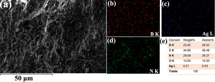
To understand the elemental contribution in nanocomposite and the filler interactions with the host–polymer matrix, energy-dispersive spectrometry (EDS)-coupled SEM analysis was carried out on PMMA–BA35. Figure 6a represents a typical SEM image of PMMA–BA35, where the elemental mapping was carried out. Figure 6b–d shows uniform distribution of filler elements like B, Ag, and N, respectively, in the polymer matrix. From Figure 6e, which is the quantitative elemental analysis, it is clear that B and N are present almost at the same weight percent, whereas the amount of AgNP came around 0.21 wt %. The low amount of AgNPs in the micrograph suggests that it is unable to form a percolation channel in the nanocomposite, and as a result, it will not significantly influence the electrical conductivity of developed nanocomposite below the percolation limits (Figure 7c).
Figure 6.
(a) SEM image of PMMA–BA35. (b–d) Elemental distribution of B, Ag, and N and (e) elemental composition.
Figure 7.
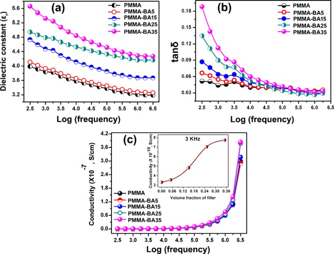
Variation of (a) dielectric constant (εr), (b) dielectric loss (tan δ), and (c) alternating current (ac) conductivity of PMMA–BAX nanocomposite with respect to log frequency (inset: variation of ac conductivity with filler content at 3 kHz).
2.4. Dielectric Properties of Nanocomposite
Besides high-thermal conductivity, the most desirable properties of polymer nanocomposites are their low dielectric constant (εr) and appreciably low dielectric loss (tanδ) that qualify them to be used as microelectronic substrates and encapsulation packages.56 The low-dielectric-constant materials are capable of decreasing the relative capacitance delay, power consumption, and cross-talk noise.57,58 Besides, the signal propagation through a microelectronic substrate is inversely proportional to its dielectric constant;58,57 therefore, low-dielectric-constant materials are extensively preferred for high-performance substrate application. In the present case, dielectric properties of PMMA–BAX nanocomposites were studied in both radiofrequencies and microwave frequencies.
Figure 7a–c shows the variation in εr, tanδ, and ac conductivity of PMMA–BAX composite in the frequency range of 300 Hz to 3 MHz. Figure 7a shows a gradual increase in εr with an increase in filler content. At lower filler content, the increment is very negligible, but as filler content increases to 0.35 Vf, there was a notable improvement in its εr. The main reason for increasing εr with filler content was due to comparatively high εr of hybrid filler (BNNS/AgNP) incorporated. This will lead to an enhancement in the average electric field in the matrix, and when more filler is added, more will be its effect.59 Second, the addition of hybrid filler tends to improve the interfacial polarization of the filler–matrix interface due to charge accumulation, which thereby results in an enhancement of dielectric constant.59 However, the maximum εr obtained for PMMA–BA35 comes below 5.6 in the entire frequency regime. In general, the dielectric constant shows a gradual decrease with frequency because at lower frequency all of the polarization mechanisms are active and with an increase in frequency the effects of interfacial and dipolar polarization are overpowered by ionic polarization, resulting in a lowering of dielectric constant.60,61 At the same time, compared to neat PMMA, the enhancement in εr after maximum filler addition (0.35 Vf) is around 34% (at 1 MHz). Interestingly, in comparison to TCE (363%) of PMMA–BA35, the enhancement in εr is very low. This result suggests that the AgNP effect is more in interconnecting BNNS to form an effective thermal short-circuit path for heat dissipation. Similarly, tan δ (Figure 7b) also shows a decreasing trend with an increase in frequency. In the lower-frequency region (up to 5 kHz), the difference is predominant, which increases with filler content. This is mainly due to the influence of interfacial polarization. When the frequency was increased above 5 kHz, the effect is weakened, and even at higher frequencies, the tanδ value of nanocomposite is almost similar to that of pristine PMMA. It takes into account that the filler particle did not increase the dielectric loss of developed nanocomposite considerably. Another crucial factor which influences the practical utility of the developed composite is the variation in ac conductivity of nanocomposite with filler content. As depicted in Figure 7c, all nanocomposites have very low conductivity in the order of 10–7 S/cm. The result concludes that all of the developed nanocomposites are highly electrically insulating and can act as a suitable candidate for the microelectronic substrate as well as package application. The inset of Figure 7c shows the variation of ac conductivity with filler content at 3 kHz. The ac conductivity varies linearly with filler content; however, the value falls below 10–10 S/cm. A higher level of accuracy in dielectric testing can be achieved at microwave frequency ranges because the dielectric polarization phenomenon is mainly dictated by ionic polarization in this regime. Temperature-dependent dielectric constants were measured in the range of 30–60 °C at 1 MHz, and the results are shown in Figure S1, Supporting Information. As the graph implies, for neat PMMA and at low filler loading, the variation of dielectric constant is almost independent of temperature. On the other hand, as the filler loading increases, the dielectric constant increase slightly with temperature. This may be due to an increase in polarizability of the nanocomposite with AgNP addition.62 The microwave dielectric properties of PMMA–BAX nanocomposites at 5 GHz are tabulated in Table 2.
Table 2. Microwave Dielectric Properties of PMMA–BAX Composites at 5 GHz.
| dielectric
properties |
||
|---|---|---|
| vol fraction | εr | tan δ |
| 0 | 2.6 | 0.0116 |
| 0.05 | 2.7 | 0.0112 |
| 0.15 | 3.0 | 0.0146 |
| 0.25 | 3.2 | 0.0163 |
| 0.35 | 3.6 | 0.0173 |
A similar trend was observed here also, that is, with an increase in filler content, both εr and tanδ increase in a monotonic way. The maximum value of εr = 3.6 was obtained for PMMA–BA35 composite.
2.5. Thermogravimetric, Mechanical, and Water Absorption Studies of PMMA–BAX Nanocomposite
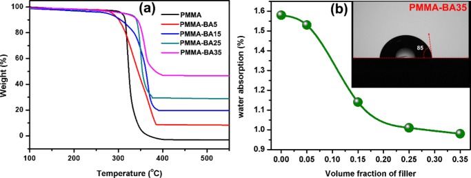
For electronic packaging applications, thermal stability and degradation behavior of polymer nanocomposites as well as water absorption should be critically evaluated. Thermal stability of the nanocomposite phase was measured by thermogravimetric analysis, and the results are shown in Figure 8a. From the figure, it is observed that the thermal stability of nanocomposites increases as a function of filler loading. The onset of thermal decomposition of PMMA was shifted from 314 to 340 °C with the addition of 0.35 Vf of hybrid filler. This is because high-thermal-conductivity AgNP/BNNS will endorse the formation of char, which will act as a barrier for mass transport that decreases the decomposition rate.63 In addition, the restricted motion of polymer chain by nanofiller will also promote the thermal stability of the composite.64
Figure 8.
(a) Thermogravimetric analysis (TGA) of PMMA–BAX with different filler loadings and (b) water absorption as a function of volume fraction of filler (inset: contact angle for PMMA–BA35).
Figure 8b shows water absorption (%) of PMMA–BAX nanocomposites as a function of filler content at room temperature. The results are quite interesting to note because with an increase in filler content the water absorption decreases gradually from 1.58 to 0.98% for PMMA–BA35. Normally, the addition of ceramic filler tends to increase water absorption due to the highly hydrophilic nature of ceramic particles. In the present case, a reverse trend is observed, which is attributed to the water-resistant nature of h-BN.7 The inset of Figure 8b shows the contact angle measurement of PMMA–BA35 at room temperature, which is found to possess a contact angle of 85°. This result substantiates the low water absorption of PMMA–BA35 discussed before.
Vickers hardness values of neat PMMA, PMMA–BA15, and PMMA–BA35 were measured by microindentation test, and the results are tabulated in Table 3. Neat PMMA has a hardness value of 178 MPa, which increases with filler addition. This is obvious because the incorporation of hard ceramic particles into polymer matrix will naturally improve its hardness value. However, the enhancement is not very pronounced, which is believed to be due to the low-hardness nature of BNNS compared to other ceramics. CTEs of neat PMMA and PMMA–BA35 were measured in the temperature range of 25–70 °C, and the results are given in Figure S2, Supporting Information. It was observed from the figure that both samples show a linear expansion as a function of temperature. The average CTE values of PMMA and PMMA–BA35 were around 87 and 77 ppm/°C, respectively.
Table 3. Vickers Microhardness.
| material | hardness (MPa) |
|---|---|
| PMMA | 178 |
| PMMA–BA15 | 194 |
| PMMA–BA35 | 189 |
3. Conclusions
BNNS decorated with AgNPs were prepared successfully through a liquid exfoliation technique. HRTEM studies reveal the formation of nanosheets and a uniform incorporation of AgNPs over BN. AFM analysis shows that exfoliated sheets have a thickness of around 2.4 nm corresponding to five to eight layers of BNNS. The novel approach to generate the nanocomposite, using AgNP-dispersed BNNS as the filler, is found to be effective in improving the thermal characteristics of PMMA. For example, the coefficient of thermal expansion (CTE) of PMMA decreased with the addition of BNNS decorated with AgNPs, and an apparent CTE of 77 ppm/°C was observed for PMMA–BA35 nanocomposite. Besides, a high-thermal conductivity of 1.48 W/m K was achieved for PMMA–BA35, and it showed an impressive thermal conductivity enhancement (TCE) of 363% compared to pristine PMMA. These results were supplemented by elemental mapping and microstructural analysis that showed a uniform distribution of filler in the matrix. The dielectric properties of nanocomposites were studied in radiofrequencies and microwave frequencies. Low εr and tanδ values were achieved for all of the nanocomposites, indicating their suitability in electronic packaging applications. Furthermore, the resistive nature of the nanocomposite is retained despite silver decoration, which is evident from its low value of ac conductivity (of the order of 10–7 S/cm). This indirectly suggests that AgNPs did not from a percolation channel in the composite. The water absorption behavior of nanocomposites decreases with filler content, and the contact angle measurement indicates a value of 85° for PMMA–BA35, revealing the low wettability of hybrid filler. Thermal stability and hardness of composites were also increased with filler amount. The nanocomposite, PMMA–BA35, has a hardness value of 189 MPa compared to 178 MPa of pristine PMMA.
In brief, the results reveal that the thermal conductivity of pristine PMMA (0.32 W/m K) can be largely improved to 1.48 W/m K by the addition of boron nitride nanosheets, where the latter were suitably decorated with silver nanoparticles. The concentration of these silver nanoparticles on BNNS can be very low enough to form conducting percolation channels. At the same time, it facilitates connections between the exfoliated BNNS, whereby the transfer of phonon mechanism gets intensified. In this way, the PMMA–BAX nanocomposite is found to be an attractive candidate for thermal management applications in the electronic packaging industry.
4. Materials and Methods
Hexagonal boron nitride powder of size ∼1 μm (98%, Sigma-Aldrich, St. Louis, MO), silver nitrate (99%, Sigma-Aldrich), and poly(methyl methacrylate) (PMMA; Nikunj Industries, Mumbai, India) were used as the starting materials. All of the raw materials were used as received without any further purification process.
4.1. Preparation of Hybrid Filler (BNNS/AgNP)
BNNS were synthesized from bulk h-BN based on typical liquid-phase exfoliation method using N,N-dimethylformamide (DMF) as the exfoliation medium.65,34 In a typical exfoliation process, h-BN nanopowder was dispersed in an excess amount of DMF solvent and effective exfoliation was carried via sonication for 48 h in an ultrasonic bath. By this continued sonication, h-BN was flaked off to form BNNS. After 48 h sonication, silver nitrate solution (dissolved in DMF) was added slowly to the exfoliated BNNS dispersion, with continuous sonication. The whole mixture was kept overnight to effectuate uniform distribution of AgNPs over exfoliated BNNS. Here, DMF plays a dual role as a solvent for h-BN exfoliation as well as a reducing agent to convert silver ion to metallic silver.34 In entire compositions, the mass ratio of h-BN to silver nitrate was kept constant (1:1). The volume fractions of h-BN and AgNP for each composite are tabulated in the Supporting Information (Table S1)
4.2. Preparation of Nanocomposite (PMMA–BNNS/AgNP)
The nanocomposites were synthesized by an in situ method. For that, PMMA dissolved in DMF was added very slowly to the above-prepared hybrid filler dispersion with continuous sonication. To ensure homogenous mixing of the filler and matrix, the sonication was further extended for one more hour. Finally, the composite was precipitated out from the DMF solvent by a rapid addition of distilled water. The resulting precipitate was collected by filtration, washed several times with distilled water to remove the nitrate ions if present, and dried overnight in a hot air oven. A series of PMMA nanocomposites were developed through this method by varying the hybrid filler loading from 0.05 to 0.35 volume fraction (Vf). Samples for thermal, mechanical, and dielectric measurements were developed by hot-pressing technique. For comparison of thermal conductivity, nanocomposites without silver nanoparticles were also synthesized via the same procedure. For the sake of simplicity, composites with and without silver nanoparticles were mentioned as PMMA–BAX and PMMA–BX, respectively, where X denotes the volume percentage of filler. The schematic representation of the entire process is shown in Figure 9.
Figure 9.
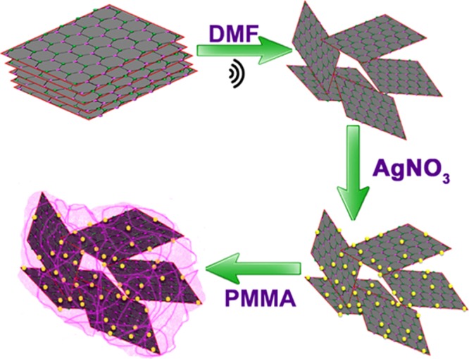
Schematic representation of synthesis of PMMA–BAX nanocomposite.
4.3. Characterization
Phase purity and presence of AgNP deposition over BNNS were analyzed by XRD (Cu Kα radiation, PANalytical X’Pert PRO diffractometer, the Netherlands). The exfoliation of nanosheets and silver decoration were further analyzed by HRTEM (FEI Tecnai G2 30S-TWIN, FEI Company, Hillsboro, OR). The thickness as well as the lateral dimension of the BNNS were examined by atomic force microscopy (AFM; Bruker MultiMode, Santa Barbara, CA). The thermal conductivity (TC) of the composites was measured using a laser flash thermal property analyzer (Flash Line 2000, Anter Corporation, Pittsburgh), which follows the relation
| 4 |
where α is the thermal diffusivity, ρ is the density, and Cp is the specific heat capacity of the composite. The Cp values of all of the composites were measured by keeping alumina (Al2O3) as the reference material. The density of the composites was measured by the Archimedes method. Fractured microstructural analysis and elemental mapping of composites were done using an EDS-coupled scanning electron microscope (Zeiss EVO 18 Cryo SEM, Jena, Germany). Water absorption tests of the composite were also done using the standard ASTM protocol. For that, initially, the samples were dried at 70 °C overnight and their weights (W1) was taken. Subsequently, the samples were soaked in distilled water for 24 h, and the final weight (W2) was measured after wiping off the surface water. Then, percentage water absorption was calculated using the equation
| 5 |
Contact angle measurements of the composite were also carried out with the aid of automated goniometer/tensiometer (model 290, Ramé-Hart Instrument Co.). Thermal stability of the composites was studied by thermogravimetric analysis (Shimadzu TGA/DTA Instrument, Japan). Microhardness measurements of representative samples were performed using Vickers microindentation hardness test (Shimadzu HMV-2TAW, Kyoto, Japan). The coefficient of linear thermal expansion (CTE) of representative samples was measured using a thermomechanical analyzer (TMA/SS7300, SII NanoTechnology Inc.) in the temperature range of 25–70 °C. The dielectric properties in the lower-frequency regime (300 Hz to 3 MHz) and their variation with temperature (30–60 °C) were studied using an LCR meter (Hioki model, 3532-50, Nagano, Japan). The microwave dielectric properties of the developed hybrid composites were measured using a split post dielectric resonator (QWED, Warsaw, Poland) operating at 5 GHz with an ENA series vector network analyzer (E5071C, Agilent Technologies, Santa Clara, CA).
Acknowledgments
The authors acknowledge the Technology System Development program of Department of Science and Technology (Ref: DST/TSG/AMT/2015/359), New Delhi, for financial assistance. P. Abhilash and Kanakangi S. Nair acknowledge Council of Scientific and Industrial Research, New Delhi, for their research fellowship.
Supporting Information Available
The Supporting Information is available free of charge on the ACS Publications website at DOI: 10.1021/acsomega.7b01436.
Volume fraction of components used in nanocomposites (Table S1); variation of dielectric constant with temperature (Figure S1); and thermal expansion behavior of PMMA and PMMA–BA35 (Figure S2) (PDF)
The authors declare no competing financial interest.
Supplementary Material
References
- Zhi C.; Bando Y.; Terao T.; Tang C.; Kuwahara H.; Golberg D. Towards Thermoconductive, Electrically Insulating Polymeric Composites with Boron Nitride Nanotubes as Fillers. Adv. Funct. Mater. 2009, 19, 1857–1862. 10.1002/adfm.200801435. [DOI] [Google Scholar]
- Kim G.-H.; Lee D.; Shanker A.; Shao L.; Kwon M. S.; Gidley D.; Kim J.; Pipe K. P. High Thermal Conductivity in Amorphous Polymer Blends by Engineered Interchain Interactions. Nat. Mater. 2015, 14, 295–300. 10.1038/nmat4141. [DOI] [PubMed] [Google Scholar]
- Varghese J.; Nair D. R.; Mohanan P.; Sebastian M. T. Dielectric, Thermal and Mechanical Properties of Zirconium Silicate Reinforced High Density Polyethylene Composites for Antenna Applications. Phys. Chem. Chem. Phys. 2015, 17, 14943–14950. 10.1039/C5CP01242B. [DOI] [PubMed] [Google Scholar]
- Seymour R. B.; Carraher C. E.. Structure – Property Relationships in Polymers; Plenum Press: New York, 1984; pp 83–93. [Google Scholar]
- Hu J.; Huang Y.; Yao Y.; Pan G.; Sun J.; Zeng X.; Sun R.; Xu J.-B.; Song B.; Wong C.-P. Polymer Composite with Improved Thermal Conductivity by Constructing a Hierarchically Ordered Three-Dimensional Interconnected Network of BN. ACS Appl. Mater. Interfaces 2017, 9, 13544–13553. 10.1021/acsami.7b02410. [DOI] [PubMed] [Google Scholar]
- Li Q.; Chen L.; Gadinski M. R.; Zhang S.; Zhang G.; Li H. U.; Iagodkine E.; Haque A.; Chen L.-Q.; Jackson T. N.; Wang Q. Corrigendum: Flexible High-Temperature Dielectric Materials from Polymer Nanocomposites. Nature 2016, 536, 112. 10.1038/nature17673. [DOI] [PubMed] [Google Scholar]
- Lin Z.; Mcnamara A.; Liu Y.; Moon K.-s.; Wong C.-P. Exfoliated Hexagonal Boron Nitride-Based Polymer Nanocomposite with Enhanced Thermal Conductivity for Electronic Encapsulation. Compos. Sci. Technol. 2014, 90, 123–128. 10.1016/j.compscitech.2013.10.018. [DOI] [Google Scholar]
- Song W.-L.; Wang W.; Veca L. M.; Kong C. Y.; Cao M.-S.; Wang P.; Meziani M. J.; Qian H.; LeCroy G. E.; Cao L.; Sun Y.-P. Polymer/carbon Nanocomposites for Enhanced Thermal Transport Properties – Carbon Nanotubes versus Graphene Sheets as Nanoscale Fillers. J. Mater. Chem. 2012, 22, 17133. 10.1039/c2jm32469e. [DOI] [Google Scholar]
- Wong C. P.; Bollampally R. S. Thermal Conductivity, Elastic Modulus, and Coefficient of Thermal Expansion of Polymer Composites Filled with Ceramic Particles for Electronic Packaging. J. Appl. Polym. Sci. 1999, 74, 3396–3403. . [DOI] [Google Scholar]
- Ganesan V.; Ellison C. J.; Pryamitsyn V. Mean-Field Models of Structure and Dispersion of Polymer-Nanoparticle Mixtures. Soft Matter 2010, 6, 4010. 10.1039/b926992d. [DOI] [Google Scholar]
- Huang C.-L.; Qian X.; Yang R.-G. Influence of Nanoparticle Size Distribution on the Thermal Conductivity of Particulate Nanocomposites. Europhys. Lett. 2017, 117, 24001 10.1209/0295-5075/117/24001. [DOI] [Google Scholar]
- Han Z.; Fina A. Thermal Conductivity of Carbon Nanotubes and Their Polymer Nanocomposites: A Review. Prog. Polym. Sci. 2011, 36, 914–944. 10.1016/j.progpolymsci.2010.11.004. [DOI] [Google Scholar]
- Mamunya Y. P.; Davydenko V. V.; Pissis P.; Lebedev E. V. Electrical and Thermal Conductivity of Polymers Filled with Metal Powders. Eur. Polym. J. 2002, 38, 1887–1897. 10.1016/S0014-3057(02)00064-2. [DOI] [Google Scholar]
- Chung D. D. L. Materials for Thermal Conduction. Appl. Therm. Eng. 2001, 21, 1593–1605. 10.1016/S1359-4311(01)00042-4. [DOI] [Google Scholar]
- Yao Y.; Zeng X.; Guo K.; Sun R.; Xu J.-b. The Effect of Interfacial State on the Thermal Conductivity of Functionalized Al2O3 Filled Glass Fibers Reinforced Polymer Composites. Composites, Part A 2015, 69, 49–55. 10.1016/j.compositesa.2014.10.027. [DOI] [Google Scholar]
- Tong X. C.Advanced Materials for Thermal Management of Electronic Packaging; Springer: New York, 2011; Vol 30. [Google Scholar]
- Huang X.; Iizuka T.; Jiang P.; Ohki Y.; Tanaka T. Role of Interface on the Thermal Conductivity of Highly Filled Dielectric epoxy/AlN Composites. J. Phys. Chem. C 2012, 116, 13629–13639. 10.1021/jp3026545. [DOI] [Google Scholar]
- Xu Y.; Chung D. D. L.; Mroz C. Thermally Conducting Aluminum Nitride Polymer–Matrix Composites. Composites, Part A 2001, 32, 1749–1757. 10.1016/S1359-835X(01)00023-9. [DOI] [Google Scholar]
- Kume S.; Yamada I.; Watari K.; Harada I.; Mitsuishi K. High-Thermal-Conductivity AlN Filler for Polymer/ceramics Composites. J. Am. Ceram. Soc. 2009, 92, S153–S156. 10.1111/j.1551-2916.2008.02650.x. [DOI] [Google Scholar]
- Wang J.; Yi X.-S. Preparation and the Properties of PMR-Type Polyimide Composites with Aluminum Nitride. J. Appl. Polym. Sci. 2003, 89, 3913–3917. 10.1002/app.12618. [DOI] [Google Scholar]
- Procter P.; Solc J. Improved Thermal Conductivity in Microelectronic Encapsulants. IEEE Trans. Compon., Hybrids, Manuf. Technol. 1991, 14, 708–713. 10.1109/33.105121. [DOI] [Google Scholar]
- Meng W.; Huang Y.; Fu Y.; Wang Z.; Zhi C. Polymer Composites of Boron Nitride Nanotubes and Nanosheets. J. Mater. Chem. C 2014, 2, 10049–10061. 10.1039/C4TC01998A. [DOI] [Google Scholar]
- Xu Y.; Chung D. D. L. Increasing the Thermal Conductivity of Boron Nitride and Aluminium Nitride Particle Epozy–Matrix Composites by Particle Surface Treatments. Compos. Interfaces 2000, 7, 243–256. 10.1163/156855400750244969. [DOI] [Google Scholar]
- Zweben C. Advances in Composite Materials for Thermal Management in Electronic Packaging. JOM 1998, 50, 47–51. 10.1007/s11837-998-0128-6. [DOI] [Google Scholar]
- Wang X.; Zhi C.; Weng Q.; Bando Y.; Golberg D. Boron Nitride Nanosheets: Novel Syntheses and Applications in Polymeric Composites. J. Phys.: Conf. Ser. 2013, 471, 012003 10.1088/1742-6596/471/1/012003. [DOI] [Google Scholar]
- Duan X.; Yang Z.; Chen L.; Tian Z.; Cai D.; Wang Y.; Jia D.; Zhou Y. Review on the Properties of Hexagonal Boron Nitride Matrix Composite Ceramics. J. Eur. Ceram. Soc. 2016, 36, 3725–3737. 10.1016/j.jeurceramsoc.2016.05.007. [DOI] [Google Scholar]
- Joseph A. M.; Nagendra B.; Gowd E. B.; Surendran K. P. Screen-Printable Electronic Ink of Ultrathin Boron Nitride Nanosheets. ACS Omega 2016, 1, 1220–1228. 10.1021/acsomega.6b00242. [DOI] [PMC free article] [PubMed] [Google Scholar]
- Rubio A.; Corkill J. L.; Cohen M. L. Theory of Graphitic Boron Nitride Nanotubes. Phys. Rev. B 1994, 49, 5081 10.1103/PhysRevB.49.5081. [DOI] [PubMed] [Google Scholar]
- Golberg D.; Bando Y.; Huang Y.; Terao T.; Mitome M.; Tang C.; Zhi C. Boron Nitride Nanotubes and Nanosheets. ACS Nano 2010, 4, 2979–2993. 10.1021/nn1006495. [DOI] [PubMed] [Google Scholar]
- Wang C.; Guo J.; Dong L.; Aiyiti A.; Xu X.; Li B. Superior Thermal Conductivity in Suspended Bilayer Hexagonal Boron Nitride. Sci. Rep. 2016, 6, 25334 10.1038/srep25334. [DOI] [PMC free article] [PubMed] [Google Scholar]
- Lindsay L.; Broido D. A. Enhanced Thermal Conductivity and Isotope Effect in Single-Layer Hexagonal Boron Nitride. Phys. Rev. B 2011, 84, 155421 10.1103/PhysRevB.84.155421. [DOI] [Google Scholar]
- Yang K.; Chen Y.; Xie Y.; Wei X. L.; Ouyang T.; Zhong J. Effect of Triangle Vacancy on Thermal Transport in Boron Nitride Nanoribbons. Solid State Commun. 2011, 151, 460–464. 10.1016/j.ssc.2011.01.002. [DOI] [Google Scholar]
- Tabarraei A.; Wang X. Anomalous Thermal Conductivity of Monolayer Boron Nitride. Appl. Phys. Lett. 2016, 108, 181904 10.1063/1.4948650. [DOI] [Google Scholar]
- Zhi C.; Bando Y.; Tang C.; Kuwahara H.; Golberg D. Large-Scale Fabrication of Boron Nitride Nanosheets and Their Utilization in Polymeric Composites with Improved Thermal and Mechanical Properties. Adv. Mater. 2009, 21, 2889–2893. 10.1002/adma.200900323. [DOI] [Google Scholar]
- Wang F.; Zeng X.; Yao Y.; Sun R.; Xu J.; Wong C.-P. Silver Nanoparticle-Deposited Boron Nitride Nanosheets as Fillers for Polymeric Composites with High Thermal Conductivity. Sci. Rep. 2016, 6, 19394 10.1038/srep19394. [DOI] [PMC free article] [PubMed] [Google Scholar]
- Lee D.; Song S. H.; Hwang J.; Jin S. H.; Park K. H.; Kim B. H.; Hong S. H.; Jeon S. Enhanced Mechanical Properties of Epoxy Nanocomposites by Mixing Noncovalently Functionalized Boron Nitride Nanoflakes. Small 2013, 9, 2602–2610. 10.1002/smll.201203214. [DOI] [PubMed] [Google Scholar]
- Donnay M.; Tzavalas S.; Logakis E. Boron Nitride Filled Epoxy with Improved Thermal Conductivity and Dielectric Breakdown Strength. Compos. Sci. Technol. 2015, 110, 152–158. 10.1016/j.compscitech.2015.02.006. [DOI] [Google Scholar]
- He Y.-M.; Wang Q.-Q.; Liu W.; Liu Y.-S. Functionalization of Boron Nitride Nanoparticles and Their Utilization in Epoxy Composites with Enhanced Thermal Conductivity. Phys. Status Solidi A 2014, 211, 677–684. 10.1002/pssa.201330305. [DOI] [Google Scholar]
- Hill R. F.; Supancic P. H. Thermal Conductivity of Platelet-Filled Polymer Composites. J. Am. Ceram. Soc. 2002, 85, 851–857. 10.1111/j.1151-2916.2002.tb00183.x. [DOI] [Google Scholar]
- Fu H. P.; Hong R. Y.; Zhang Y. J.; Li H. Z.; Xu B.; Zheng Y.; Wei D. G. Preparation and Properties Investigation of PMMA/silica Composites Derived from Silicic Acid. Polym. Adv. Technol. 2009, 20, 84–91. 10.1002/pat.1226. [DOI] [Google Scholar]
- Cui Z.; Martinez A. P.; Adamson D. H. PMMA Functionalized Boron Nitride Sheets as Nanofillers. Nanoscale 2015, 7, 10193–10197. 10.1039/C5NR00936G. [DOI] [PubMed] [Google Scholar]
- Wang J.; Zhao D.; Zou X.; Mao L.; Shi L. The Exfoliation and Functionalization of Boron Nitride Nanosheets and Their Utilization in Silicone Composites with Improved Thermal Conductivity. J. Mater. Sci.: Mater. Electron. 2017, 28, 12984–12994. 10.1007/s10854-017-7130-0. [DOI] [Google Scholar]
- Wang F.; Yao Y.; Zeng X.; Huang T.; Sun R.; Xu J.; Wong C.-P. Highly Thermally Conductive Polymer Nanocomposites Based on Boron Nitride Nanosheets Decorated with Silver Nanoparticles. RSC Adv. 2016, 6, 41630–41636. 10.1039/C6RA00358C. [DOI] [Google Scholar]
- Xia C.; Garcia A. C.; Shi S. Q.; Qiu Y.; Warner N.; Wu Y.; Cai L.; Rizvi H. R.; D’Souza N. A.; Nie X. Hybrid Boron Nitride–Natural Fiber Composites for Enhanced Thermal Conductivity. Sci. Rep. 2016, 6, 34726 10.1038/srep34726. [DOI] [PMC free article] [PubMed] [Google Scholar]
- Yao Y.; Zeng X.; Sun R.; Xu J.-B.; Wong C.-P. Highly Thermally Conductive Composite Papers Prepared Based on the Thought of Bioinspired Engineering. ACS Appl. Mater. Interfaces 2016, 8, 15645–15653. 10.1021/acsami.6b04636. [DOI] [PubMed] [Google Scholar]
- Mi Y.-n.; Liang G.; Gu A.; Zhao F.; Yuan L. Thermally Conductive Aluminum Nitride–Multiwalled Carbon Nanotube/cyanate Ester Composites with High Flame Retardancy and Low Dielectric Loss. Ind. Eng. Chem. Res. 2013, 52, 3342–3353. 10.1021/ie3029569. [DOI] [Google Scholar]
- Zhang X.; Zhang X.; Yang M.; Yang S.; Wu H.; Guo S.; Wang Y. Ordered Multilayer Film of (Graphene Oxide/polymer and Boron Nitride/polymer) Nanocomposites: An Ideal EMI Shielding Material with Excellent Electrical Insulation and High Thermal Conductivity. Compos. Sci. Technol. 2016, 136, 104–110. 10.1016/j.compscitech.2016.10.008. [DOI] [Google Scholar]
- Thomas P.; Ravindran R. S. E.; Varma K. B. R. In Dielectric Properties of Poly(methyl methacrylate) (PMMA)/CaCu3Ti4O12 Composites, 2012 IEEE 10th International Conference on the Properties and Applications of Dielectric Materials; IEEE, 2012; pp 1–4.
- Hussien B. The D.C and A.C Electrical Properties of (PMMA–Al2O3) Composites. Eur. J. Sci. Res. 2011, 52, 1450. [Google Scholar]
- Thomas P.; Dakshayini B. S.; Kushwaha H. S.; Vaish R. Effect of Sr2TiMnO6 Fillers on Mechanical, Dielectric and Thermal Behaviour of PMMA Polymer. J. Adv. Dielectr. 2015, 05, 1550018 10.1142/S2010135X15500186. [DOI] [Google Scholar]
- Chen J.; Huang X.; Zhu Y.; Jiang P. Cellulose Nanofiber Supported 3D Interconnected BN Nanosheets for Epoxy Nanocomposites with Ultrahigh Thermal Management Capability. Adv. Funct. Mater. 2017, 27, 1604754 10.1002/adfm.201604754. [DOI] [Google Scholar]
- Warzoha R. J.; Fleischer A. S. Heat Flow at Nanoparticle Interfaces. Nano Energy 2014, 6, 137–158. 10.1016/j.nanoen.2014.03.014. [DOI] [Google Scholar]
- Nan C.-W.; Birringer R.; Clarke D. R.; Gleiter H. Effective Thermal Conductivity of Particulate Composites with Interfacial Thermal Resistance. J. Appl. Phys. 1997, 81, 6692–6699. 10.1063/1.365209. [DOI] [Google Scholar]
- Huang T.; Zeng X.; Yao Y.; Sun R.; Meng F.; Xu J.; Wong C. Boron Nitride@graphene Oxide Hybrids for Epoxy Composites with Enhanced Thermal Conductivity. RSC Adv. 2016, 6, 35847–35854. 10.1039/C5RA27315C. [DOI] [Google Scholar]
- Foygel M.; Morris R. D.; Anez D.; French S.; Sobolev V. L. Theoretical and Computational Studies of Carbon Nanotube Composites and Suspensions: Electrical and Thermal Conductivity. Phys. Rev. B 2005, 71, 104201 10.1103/PhysRevB.71.104201. [DOI] [Google Scholar]
- Joseph A. M.; Nagendra B.; Surendran K. P.; Gowd E. B. Syndiotactic Polystyrene/Hybrid Silica Spheres of POSS Siloxane Composites Exhibiting Ultralow Dielectric Constant. ACS Appl. Mater. Interfaces 2015, 7, 19474–19483. 10.1021/acsami.5b05933. [DOI] [PubMed] [Google Scholar]
- Vengatesan M. R.; Devaraju S.; Dinakaran K.; Alagar M. SBA-15 Filled Polybenzoxazine Nanocomposites for Low-K Dielectric Applications. J. Mater. Chem. 2012, 22, 7559. 10.1039/c2jm16566j. [DOI] [Google Scholar]
- Ariraman M.; Sasikumar R.; Alagar M. Cyanate Ester Tethered POSS/BACY Nanocomposites for Low-K Dielectrics. Polym. Adv. Technol. 2016, 27, 597–605. 10.1002/pat.3724. [DOI] [Google Scholar]
- Luo B.; Wang X.; Wang Y.; Li L. Fabrication, Characterization, Properties and Theoretical Analysis of ceramic/PVDF Composite Flexible Films with High Dielectric Constant and Low Dielectric Loss. J. Mater. Chem. A 2014, 2, 510–519. 10.1039/C3TA14107A. [DOI] [Google Scholar]
- Pullanchiyodan A.; Surendran K. P. Formulation of Sol–Gel Derived Bismuth Silicate Dielectric Ink for Flexible Electronics Applications. Ind. Eng. Chem. Res. 2016, 55, 7108–7115. 10.1021/acs.iecr.6b00871. [DOI] [Google Scholar]
- El-Mallah H. M. AC Electrical Conductivity and Dielectric Properties of Perovskite (Pb,Ca)TiO3 Ceramic. Acta Phys. Pol., A 2012, 122, 174–179. 10.12693/APhysPolA.122.174. [DOI] [Google Scholar]
- Wang H.-W.; Shieh C.-F.; Chang K.-C.; Chu H.-C. Synthesis and Dielectric Properties of Poly(methyl Methacrylate)-Clay Nanocomposite Materials. J. Appl. Polym. Sci. 2005, 97, 2175–2181. 10.1002/app.21817. [DOI] [Google Scholar]
- Yang N.; Xu C.; Hou J.; Yao Y.; Zhang Q.; Grami M. E.; He L.; Wang N.; Qu X. Preparation and Properties of Thermally Conductive Polyimide/boron Nitride Composites. RSC Adv. 2016, 6, 18279–18287. 10.1039/C6RA01084A. [DOI] [Google Scholar]
- Ye Y.-S.; Yen Y.-C.; Cheng C.-C.; Syu Y.-J.; Huang Y.-J.; Chang F.-C. Polytriazole/clay Nanocomposites Synthesized Using in Situ Polymerization and Click Chemistry. Polymer 2010, 51, 430–436. 10.1016/j.polymer.2009.11.015. [DOI] [Google Scholar]
- Cui Z.; Oyer A. J.; Glover A. J.; Schniepp H. C.; Adamson D. H. Large Scale Thermal Exfoliation and Functionalization of Boron Nitride. Small 2014, 10, 2352–2355. 10.1002/smll.201303236. [DOI] [PubMed] [Google Scholar]
Associated Data
This section collects any data citations, data availability statements, or supplementary materials included in this article.


