Abstract
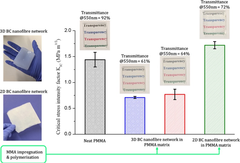
Cellulose nanofibers are often explored as biobased reinforcement for the production of high-performance composite materials. In this work, we fabricated transparent poly(methyl methacrylate) (PMMA) composites consisting of two-dimensional and three-dimensional bacterial cellulose (BC) nanofiber networks. Three different composite designs consisting of 1 vol % BC loading were fabricated and studied: (i) composites with a three-dimensional BC nanofiber network embedded uniformly throughout the PMMA matrix; (ii) sandwich-structured construction consisting of three-dimensional BC–PMMA sandwiched between two neat PMMA sheets; and (iii) dried and well-consolidated two-dimensional BC nanofiber network embedded in a PMMA matrix. All fabricated model BC–PMMA composites were found to be optically transparent, but PMMA composites consisting of the two-dimensional BC nanofiber network possessed higher light transmittance (73% @550 nm) compared to the three-dimensional BC nanofiber network counterparts (63% @550 nm). This is due to the higher specific surface area of the three-dimensional BC nanofiber network, which led to more light scattering. Nevertheless, it was found that both two-dimensional and three-dimensional BC nanofiber networks serve as excellent stiffening agents for PMMA matrix, improving the tensile modulus of the resulting composites by up to 30%. However, no improvement in tensile strength was observed. The use of three-dimensional BC nanofiber network led to matrix embrittlement, reducing the tensile strain-at-failure, fracture resistance, and Charpy impact strength of the resulting BC–PMMA composites. When the BC nanofiber network was used as two-dimensional reinforcement, cracks were observed to propagate through the debonding of BC nanofiber network, leading to higher fracture toughness and Charpy impact strength. These novel findings could open up further opportunities in the design of novel optically transparent polymeric composite laminates based on the two-dimensional BC nanofiber network for impact protection.
Introduction
Microbially-synthesized cellulose, more commonly known as bacterial cellulose (BC), is a lightweight (∼1.5 g cm–3) biomaterial produced by the fermentation of low molecular weight sugars using cellulose-producing Komagataeibacter.1 It is an ultrapure form of cellulose nanofibers with diameters between 25 and 80 nm.2,3 BC is synthesized as a three-dimensional nanofiber network in the form of a thick biofilm (e.g., a pellicle) floating on the surface of a static culture medium.4 In its wet state, a BC pellicle is tough and resistant to tear, especially in the in-plane direction.5 In its dried and well-consolidated state, the dense two-dimensional BC nanofiber network possesses a tensile modulus of up to 18 GPa and tensile strength of up to 260 MPa.6 The high tensile modulus of two-dimensional BC nanofiber network stems from the high tensile modulus of a single BC nanofiber, which has been estimated to be 114 GPa,7 as well as the high degree of hornification (e.g., irreversible hydrogen bond formation between the BC nanofibers).
Gindl and Keckes8 first reported the reinforcing ability of BC for polymers; cellulose acetate butyrate (CAB) was used as the polymer matrix in their study. At a BC loading of 32 vol %, the resulting BC-reinforced CAB composite possessed a tensile modulus and strength of 5.8 GPa and 129 MPa, respectively, a five-fold increase over neat CAB. BC has also been studied as reinforcement for phenol–formaldehyde (PF) resin.9 At a BC loading of ∼88 wt %, the resulting BC-reinforced PF composites possessed a tensile modulus and strength of 28 GPa and 425 MPa, respectively. Optically transparent BC-reinforced polyurethane (PU) composites with tensile modulus of up to 6.0 GPa and tensile strength of up to 69.5 MPa, at a BC loading of 79 wt % have also been reported.10 Neat PU, on the other hand, was found to possess a tensile modulus of only 0.016 GPa and a tensile strength of only 2.3 MPa. Yano et al.11 fabricated optically transparent BC-reinforced epoxy composites. At a BC loading of 65 wt %, the resulting composite possessed tensile modulus and strength as high as 21 GPa and 325 MPa, respectively, and coefficient of thermal expansion as low as 6 ppm °C–1.
Although it is evident that BC has the ability to act as excellent reinforcement for the production of transparent composites with high tensile stiffness and strength, the resulting thin film (<100 μm) BC-reinforced polymer composites reported in the literature often utilized dense two-dimensional BC nanofiber network as reinforcement. The BC-reinforced polymer composites produced in the aforementioned studies started with thick pellicles consisting of three-dimensional BC nanofiber networks that were either: (i) solvent-exchanged into a polymer solution, followed by solvent removal and heat consolidation or (ii) dried and consolidated, followed by resin impregnation and curing. As a result, the three-dimensional BC nanofiber network within the BC pellicle is compressed into a dense two-dimensional cellulose nanofiber network.
As three-dimensional BC nanofiber networks possess high specific area (∼160 m2 g–1),12 it can be anticipated that utilizing a three-dimensional BC nanofiber network as reinforcement will not only enhance the tensile performance but also improve both the fracture resistance and impact strength of the resulting BC-reinforced composites. The introduction of such three-dimensional BC nanofiber network into a polymer matrix will introduce additional energy absorbing mechanisms, including fiber-matrix debonding (due to an increase in fiber-polymer matrix interface), fiber reorientation and fracture, enhancing the fracture resistance and impact strength of the resulting composites.
Nonetheless, a previous study of ours13 showed that a dried and well-consolidated dense two-dimensional BC nanofiber network possessed a single edge-notched fracture toughness (KIc) value of 6.6 MPa m1/2, comparable to that of the KIc value of a single aramid fiber, measured to be 6.63 MPa m1/2.14 The high KIc value of a dried and well-consolidated dense two-dimensional BC nanofiber network stems from its high degree of hornification, which requires a substantial amount of energy to cause nanofiber–nanofiber debonding. The introduction of such dense BC nanofiber network as a two-dimensional reinforcement into a brittle polymer is postulated to produce BC-reinforced polymer composites with enhanced fracture toughness.
With research into cellulose nanofibers for various advanced engineering applications expected to intensify, it is important to identify the potential of two-dimensional and three-dimensional cellulose nanofiber networks as reinforcement not only to enhance tensile properties but also the fracture resistance and impact strength of polymers. Therefore, in this work, we report the properties of optically transparent poly(methyl methacrylate) (PMMA) composites consisting of two-dimensional and three-dimensional BC nanofiber networks. The aim is to elucidate, if any, the different BC nanofiber network architectures on the transparency, tensile properties, fracture toughness, and impact strength of the resulting BC-reinforced PMMA composites.
Results and Discussion
In this work, three different BC–PMMA composites were prepared (see Figure 1): (i) composite I, a 3 mm thick PMMA composite consisting of a three-dimensional BC nanofiber network embedded in the PMMA matrix uniformly, (ii) composite II, a 3 mm thick sandwich construction consisting of a 1.5 mm thick three-dimensional BC–PMMA composite (with the BC nanofiber network embedded within uniformly) laminated between two neat PMMA sheets, and (iii) composite III, consisting of a dried and well-consolidated two-dimensional BC nanofiber network embedded in a 3 mm thick PMMA composite. All composites possessed a BC loading of 1 vol %.a
Figure 1.
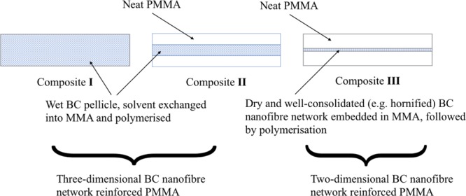
Model BC–PMMA composites fabricated and studied in this work.
The light transmittance spectra of neat PMMA and the fabricated model BC–PMMA composites are shown in Figure 2. Although neat PMMA has a transmittance of 92% in the visible light spectrum of between 400 and 700 nm, the introduction of BC led to a decrease in the transparency of the resulting model BC–PMMA composites. The light transmittance of BC–PMMA composites at a wavelength of 700 nm was found to be 74–81%. At a wavelength of 400 nm, the light transmittances reduced to only 38–54%, depending on the reinforcing BC nanofiber network architecture. Transparency in fiber-reinforced composite materials can be achieved by reducing the lateral size of the reinforcing fibers and/or via refractive index matching between the reinforcing fibers and the surrounding polymer matrix.15,16 It should also be noted that achieving transparency through refractive index between the reinforcing fibers and the surrounding polymer matrix requires the indices to be matched to the third decimal place.17 Cellulose fibers have a refractive index of 1.618 along the fiber and 1.544 in the transverse direction,18 whereas PMMA has a refractive index of 1.488.19 Due to this mismatch in refractive indices, light scattering at the BC nanofiber–PMMA interface occurred, leading to slight loss in transparency of the BC–PMMA composites.
Figure 2.
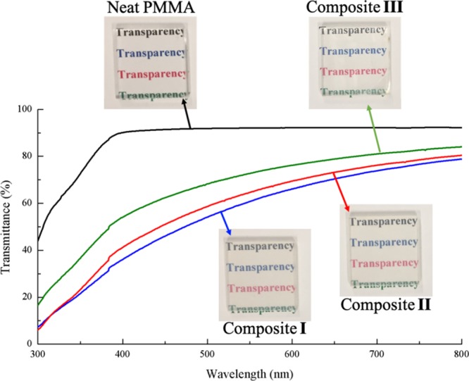
Optical transmittance of neat PMMA and BC–PMMA composites fabricated in this work.
As a result of light scattering at the BC nanofiber–PMMA interface, the reinforcing BC nanofiber network architecture also has an influence on the transparency of the resulting BC–PMMA composites, even though all composites have the same BC loading. Composite I, which consisted of a three-dimensional BC nanofiber network embedded in the PMMA matrix uniformly and composite II, with its sandwich-structured construction consisting of BC–PMMA composites sandwiched between two neat PMMA sheets, possessed similar level of light transmittance across the wavelength of visible light (see Figure 2). The light transmittance through composite III, PMMA embedded with a sheet of dried and well-consolidated dense two-dimensional BC nanofiber network, was found to be higher than both composites I and II. These results corroborated with the specific surface areas of different reinforcing BC nanofiber network architectures for the model PMMA composites (see Table 1). The surface area of the three-dimensional BC nanofiber network architectures for composites I and II were found to be similar, measured to be 78 and 71 m2 g–1, respectively. In contrast, the surface area of a dried and well-consolidated dense two-dimensional BC nanofiber network was measured to be only 41 m2 g–1. Consequently, the interfacial area between the reinforcing BC nanofiber and PMMA matrix was lower in composite III compared to composites I and II, reducing light scattering and improving its transparency.
Table 1. Specific Surface Area (As) of BC Nanofiber Network Used in This Study.
| BC nanofiber network | As (m2 g–1) |
|---|---|
| freeze-dried BC nanofiber network (3 mm thick) | 78 |
| freeze-dried BC nanofiber network (1.5 mm thick) | 71 |
| dried and well-consolidated BC nanofiber network | 41 |
In order to produce composites I and II, solvent exchange steps were used. Residual solvents (e.g., water or acetone) could still remain in the PMMA matrix, affecting its degree of polymerization and hence, its thermal and mechanical properties. This could complicate the delineation of the effects of residual solvent or the degree of polymerization of PMMA and the reinforcing ability of different BC nanofiber network architectures when analyzing the measured mechanical properties of the composites fabricated in this work. Eriksson et al.20 found that PMMA composites manufactured using solvent-based preparation methods exhibited lower glass transition temperature (Tg) due to residual solvent remaining within PMMA. Patra et al.21 observed that solvents did not only influence the thermal properties but also the mechanical properties of PMMA. The presence of solvents such as toluene or chloroform in PMMA caused polymer chain distortion, which led to a reduction in both Tg and mechanical properties of PMMA. Therefore, differential scanning calorimetry (DSC) was used to investigate the effect of solvent on the thermal properties of PMMA in this work (see Figure 3). Both neat PMMA and model BC–PMMA composites were found to possess similar Tg of ∼116 °C in the DSC traces of both first and second heating, consistent with the Tg of cell-casted neat PMMA.22 Our DSC data indicated that our solvent exchange steps did not affect the degree of polymerization of the PMMA matrix in composites I and II. In addition to this, none of the DSC trace exhibited additional exothermic peaks, which further indicated that the polymerization of methyl methacrylate (MMA) was complete for all samples. These results showed that the measured mechanical properties of the BC–PMMA composites could be attributed to the differences in the reinforcing BC nanofiber network architectures within the PMMA matrix.
Figure 3.
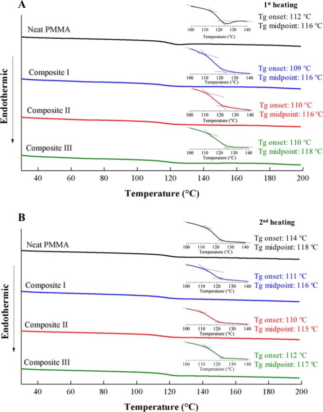
DSC traces of neat PMMA and BC–PMMA composites. (A) DSC traces based on first heating and (B) DSC traces based on second heating.
The tensile properties of neat PMMA and the model BC–PMMA composites are summarized in Table 2. Their respective stress–strain curves are shown in Figure 4. It can be seen from Table 2 that by introducing 1 vol % of BC into PMMA, the tensile modulus of the resulting composites improved by ∼20–30% compared to neat PMMA. These results suggested that both two-dimensional and three-dimensional BC nanofiber networks serve as excellent reinforcement to produce PMMA composites with improved tensile modulus. The improvements in the tensile modulus of composites I and II are thought to stem from the high tensile modulus of single BC nanofiber, estimated to be up to 114 GPa,7 whereas the increase in tensile modulus of composite III stems from the high tensile modulus of a dried and well-consolidated dense two-dimensional BC nanofiber network, measured to be 19.6 GPa (see Table 2). However, no improvement in tensile strength was observed when BC was used as reinforcement for PMMA. All BC–PMMA composites possessed similar tensile strength of ∼70 MPa, similar to that of neat PMMA. This could be attributed to the low BC loading introduced into the PMMA matrix. Furthermore, tensile strength of a material is a complex property that depends on the process of failure.23 The introduction of BC into PMMA led to matrix embrittlement, resulting in an earlier onset failure of the final BC–PMMA composites and the lack of improvements in the tensile strength of the model BC–PMMA composites. This was evident by the reduction of the strain-at-failure of the composites (Table 2).
Table 2. Tensile Properties of Neat PMMA, Dried and Well-Consolidated BC Nanofiber Network, and the Fabricated BC–PMMA Composites with Three Different Reinforcing BC Nanofiber Network Architecturesa.
| sample | E (GPa) | σ (MPa) | ε (%) |
|---|---|---|---|
| neat PMMA | 3.4 ± 0.4 | 72 ± 2 | 4.2 ± 0.6 |
| composite I | 4.5 ± 0.6 | 69 ± 4 | 2.2 ± 0.1 |
| composite II | 4.0 ± 0.2 | 71 ± 4 | 2.6 ± 0.3 |
| composite III | 4.2 ± 0.2 | 69 ± 5 | 3.3 ± 0.2 |
| dried and well-consolidated two-dimensional BC nanofiber network | 19.6 ± 0.3 | 188 ± 9 | 1.4 ± 0.1 |
E, σ, and ε correspond to tensile modulus, tensile strength, and strain-at-failure, respectively.
Figure 4.
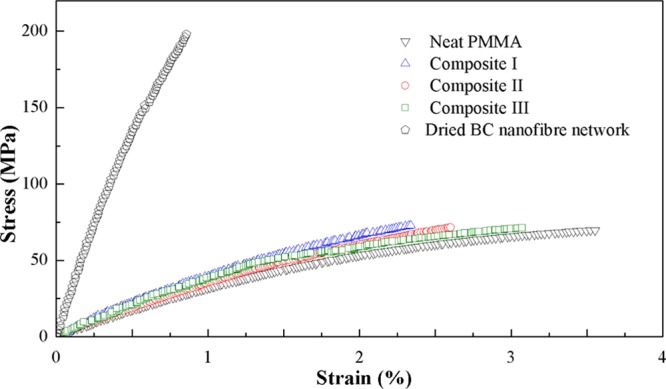
Representative tensile stress–strain curves of neat PMMA, BC–PMMA composites fabricated in this work, and dried and well-consolidated dense BC nanofiber network.
The strain-at-failure of the composites increased with progressively denser reinforcing BC nanofiber network architectures; from 2.2% for composite I to 2.6% for composite II, and 3.4% for composite III. Neat PMMA, on the other hand, possessed a higher strain-to-failure of ∼4%. One of the main advantages of using BC as three-dimensional reinforcement is its high surface area. However, this high surface area also led to a decrease in strain-at-failure of the resulting BC–PMMA composites. This is hypothesized to be due to the high volumetric shrinkage of MMA to PMMA during polymerization, measured up to 27% in our work. Such shrinkage could occur either at the BC nanofiber–PMMA interface or at the crosslinking points between two BC nanofibers and PMMA. Both scenarios will lead to a notch-like effect, serving as crack initiator and contribute to the embrittlement of the resulting composites.24 The low surface area of the dried and well-consolidated dense two-dimensional BC nanofiber network reduced this notch-like effect in composite III because of the reduction in the BC nanofiber-polymer matrix interface compared to composites I and II.
The fracture resistance of neat PMMA and model BC–PMMA composites was investigated by performing single-edge notched bending (SENB) loaded in the 3-point bending mode. Their representative load–displacement curves are shown in Figure 5. The initial linear part of the load–displacement curves corresponded to an elastic response. This was then followed by a decrease in the load, which indicated crack propagation until the specimen failed. Both the initial gradient of the load–displacement curves and the specimen displacement at which crack propagated of the neat PMMA and BC–PMMA composites corroborated with their measured tensile modulus and strain-at-failure, respectively. The initial critical stress intensity factor (KIc) values of neat PMMA and the model BC–PMMA composites are summarized in Table 3. When BC nanofiber network was used as three-dimensional reinforcement for PMMA, both composites I and II exhibited similar KIc values of only 0.71 and 0.77 MPa m1/2, respectively, which was half of the KIc value obtained for neat PMMA (KIc = 1.44 MPa m1/2). These low KIc values can be attributed to the low strain-at-failure of the composites. However, when BC nanofiber network was used as two-dimensional reinforcement for PMMA (composite III), a KIc value of 1.72 MPa m1/2 was measured, a 20% increase over neat PMMA. This can be attributed to the reduced brittleness of composite III compared to composites I and II. In addition to this, dried and well-consolidated dense two-dimensional BC nanofiber network was found to possess a KIc value of 6.6 MPa m1/2,13 which also contributed to the higher KIc value of composite III.
Figure 5.
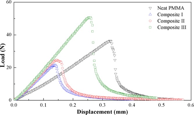
Representative load–displacement curves of single-edge notched beam specimens loaded in 3-point bending mode.
Table 3. Initial Critical Stress Intensity Factor (K1c) and Charpy Impact Strength in the Edgewise and Flatwise Direction of Neat PMMA and BC–PMMA Composites.
| impact strength (kJ m–2) |
|||
|---|---|---|---|
| sample | K1c (MPa m1/2) | edgewise | flatwise |
| neat PMMA | 1.44 ± 0.14 | 12.7 ± 0.7 | 6.3 ± 0.3 |
| composite I | 0.71 ± 0.02 | 8.7 ± 2.5 | 4.7 ± 0.1 |
| composite II | 0.77 ± 0.10 | 9.2 ± 1.9 | 5.8 ± 0.6 |
| composite III | 1.72 ± 0.07 | 13.1 ± 0.7 | 7.6 ± 0.3 |
Charpy impact test was further conducted to determine whether both two-dimensional and three-dimensional BC nanofiber networks will serve as reinforcement to improve the impact resistance of neat PMMA. The Charpy impact strength of neat PMMA and BC–PMMA composites tested in the edgewise and flatwise directions are tabulated in Table 3. Neat PMMA was found to possess a Charpy impact strength of 12.7 kJ m–2 in the edgewise direction and 6.3 kJ m–2 in the flatwise direction. When BC nanofiber network was used as three-dimensional reinforcement (composites I and II), the measured Charpy impact strength decreased by up to 30% in the edgewise direction and 25% in the flatwise direction. The Charpy impact strength of composite III was found to be 13.1 kJ m–2 (edgewise) and 7.6 kJ m–2 (flatwise); which represented an increase of 8% in the edgewise and 21% in the flatwise directions compared to neat PMMA and ∼60% (both edgewise and flatwise) over composite I, which utilized BC nanofiber network as three-dimensional reinforcement. The low impact strength of composites I and II compared to composite III is thought to be due to matrix embrittlement when high surface area three-dimensional BC nanofiber network was incorporated into the matrix (see Table 2).
Both the fracture toughness and impact strength of the model BC–PMMA composites were further corroborated with fractographic observations. The fracture surfaces of SENB specimens of neat PMMA and BC–PMMA composites are shown in Figure 6. Some degree of plastic flow can be observed in the fracture surfaces of neat PMMA (Figure 6A), evident by the presence of textured microflow. The fracture surface of composite I (Figure 6B) possessed a rough surface that indicated the absence of plastic deformation; the crack propagated very quickly due to the brittleness of the PMMA matrix embedded with BC nanofibers. Composite II (Figure 6C) exhibited a rougher surface at the center of the composite than at its edges where there was just neat PMMA. The crack in composite II is thought to start at the center in its most brittle region and propagated outwards to the PMMA-rich region. However, when PMMA was reinforced with dried and well-consolidated two-dimensional BC nanofiber network, a different fracture mechanism was observed. It can be seen from Figure 6D that the dried and well-consolidated two-dimensional BC nanofiber network delaminated and defibrillated as the crack propagated through, whereas the PMMA-rich region fractured in a manner similar to that of neat PMMA.
Figure 6.
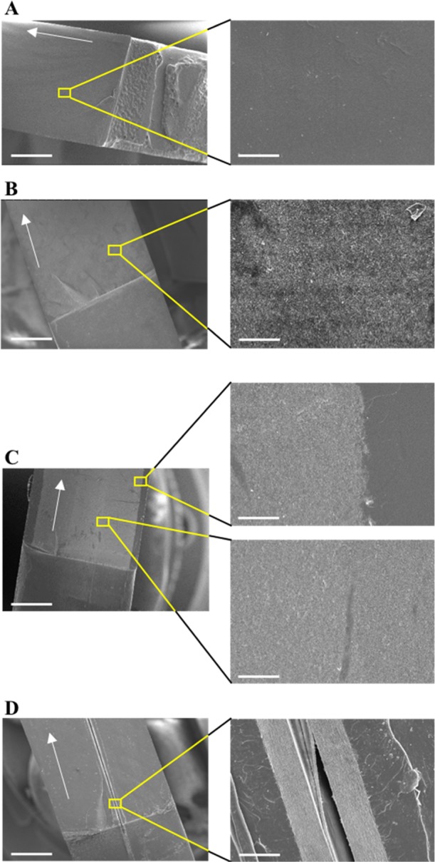
Fracture surfaces of SENB specimens; (A) neat PMMA, (B) composite I, (C) composite II, and (D) composite III. The arrows indicate the direction of the crack growth. The scale bars at low and high magnifications correspond to 1 mm and 50 μm, respectively.
Figure 7 shows the fracture surfaces of neat PMMA and BC–PMMA composites failed under impact of a pendulum swing of a Charpy impact tester in the flatwise direction. Three very different fracture morphologies can be observed. Neat PMMA is a brittle polymer but some degree of plastic flow, indicated by the presence of cusps (inclined platelets on the surface)25 can still be seen (Figure 7A). However, such morphologies associated with plastic deformation were absent from composites I and II (Figure 7B,C). Instead, rugged surface morphology without any well-defined cusps or textured microflow were observed. This is indicative of matrix embrittlement. The fracture surfaces for composites I and II exhibited the fractographic phenomenon of “mirror/mist/hackle”, which is typical in brittle materials.26 The “mirror” region corresponded to a smoother area in which the crack slowly formed. As the fracture accelerated, a region called “mist” was produced with the presence of scarps and riverlines pointing toward the direction of crack growth. Eventually, as the crack growth reached its terminal velocity, distinct riverlines were formed in the “hackle” region.
Figure 7.
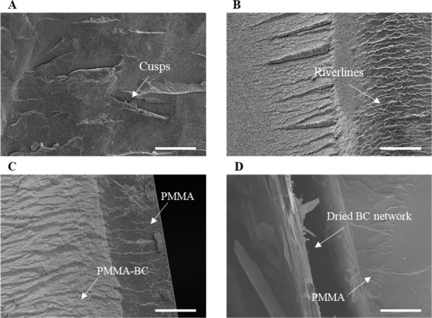
Fracture surfaces of (A) neat PMMA, (B) composite I, (C) composite II, and (D) composite III, respectively, tested in the flatwise Charpy impact test. The scale bar corresponds to 100 μm.
These fractographic observations further corroborated with the higher KIc values and Charpy impact strength of composite III compared to composites I and II. When the BC nanofiber network was used as three-dimensional reinforcement for PMMA, matrix embrittlement could be observed, leading to lower KIc values and Charpy impact strength of composites I and II. When the BC nanofiber network was used as two-dimensional reinforcement for PMMA, crack propagated through the debonding BC nanofiber network, which is a high energy absorbing mechanism. Furthermore, the minimization of BC nanofiber–PMMA interface when the BC nanofiber network was used as two-dimensional reinforcement reduced the matrix embrittlement effect that was observed for composites I and II. Both of these effects led to higher KIc values and Charpy impact strength for composite III.
Conclusions
In this work, we report the properties of optically transparent PMMA composites consisting of two-dimensional and three-dimensional BC nanofiber networks. Light transmittance measurements showed that two-dimensional BC nanofiber network-reinforced PMMA composites possessed higher light transmittance (74–81%) compared to their three-dimensional counterparts (38–54%). This is due to the reduction in BC–PMMA interface, which reduced the degree of light scattering and increased the level of light transmittance. These results also corroborated with the specific surface area of two-dimensional (41 m2 g–1) and three-dimensional (∼71–78 m2 g–1) BC nanofiber networks in the PMMA matrix. Both two-dimensional and three-dimensional BC nanofiber networks were found to serve as excellent stiffening agent for PMMA. At 1 vol % BC loading, the tensile moduli of the model BC–PMMA composites were found to be 4.0–4.5 GPa, independent of the reinforcing BC nanofiber network architecture. Neat PMMA was found to possess a tensile modulus of only 3.4 GPa. In terms of fracture toughness and Charpy impact strength, the matrix embrittlement effect due to the introduction of three-dimensional BC nanofiber network reinforcement for PMMA led to a decrease in KIc values by 50% and flatwise impact strength by 30% compared to neat PMMA. When two-dimensional BC nanofiber network was used as two-dimensional reinforcement for PMMA, crack propagated through the debonding BC nanofiber network, a high energy absorbing mechanism, leading to improvements in KIc values by 20% and flatwise impact strength by 20% over neat PMMA. Our results suggest that two-dimensional BC nanofiber network will serve as better reinforcement for polymers to produce composites with improved fracture resistance and impact strength. These novel findings could open up further opportunities in the design of novel optically transparent polymeric composite laminates based on two-dimensional BC nanofiber networks for impact protection.
Experimental Section
Materials
Acetone (GPR RECTAPUR, purity > 99.5%) and sodium hydroxide (pellets, AnalaR NORMAPUR, purity > 98.5%) were purchased from VWR International Ltd. (Lutterworth, UK). MMA (Aldrich, purity ≥ 99%, inhibited with ≤ 30 ppm monomethyl ether hydroquinone) and 2,2′-azobis (2-methylpropionitrile) (AIBN) (Aldrich, purity ≥ 98%) were purchased from Sigma-Aldrich and used as the monomer and free-radical initiator, respectively. These chemicals were used as received without further purification. BC in the form wet pellicle with a water content of 98 wt % was purchased from a commercial retailer (Vietcoco International Co. Ltd., Ho Chi Minh City, Vietnam).
Purification of BC Pellicles
The purification protocol of BC pellicles adopted in this study was adapted from the purification of BC from blended nata de coco cubes13,27,28 but modified to ensure that the three-dimensional BC nanofiber network within the pellicle was not disrupted. In brief, as-received BC pellicle (wet pellicle weight of ∼175 g, dry BC weight of ∼3.5 g) was soaked in 4 L of deionized water and heated to 80 °C under magnetic stirring. Once the desired temperature was reached, 16 g of NaOH pellets were added and the BC pellicle was left to stir in this 0.1 M NaOH solution at 80 °C for 2 h to remove any remaining microorganisms or soluble polysaccharides. The purified BC pellicle was then recovered and rinsed with 5 L of deionized water before immersing in fresh deionized water under magnetic stirring until neutral pH was attained. The purified BC pellicle was then kept hydrated and stored in a 4 °C fridge before subsequent use.
Preparation of Neat PMMA Sheets
Neat PMMA sheets were produced using a cell-cast process.29 AIBN (0.05 wt %) was dissolved in 50 g of MMA and prepolymerized at 70 °C for 2 h in a water bath to first produce a viscous MMA syrup. The MMA syrup was then poured into a cell-casting mold consisting of two 6 mm thick glass panels (12 cm × 12 cm) sandwiched between a 3 mm thick polytetrafluoroethylene (PTFE) gasket. The mold was clamped on all sides using foldback clips to ensure that the viscous MMA syrup did not leak out of the mold. The MMA syrup in the cell-casting mold was then polymerized at 50 °C in an oven for 20 h, followed by 85 °C for another 2 h. A postpolymerization step at 125 °C overnight was then employed.
Preparation of Model BC–PMMA Composites
Before producing composites I and II, a solvent exchange route was employed. Purified BC pellicle with dimensions of 7 cm × 7 cm × 10 mm was first gently pressed between filter papers (Qualitative filter paper 413, VWR, Lutterworth, UK) to remove some of the excess water before solvent exchanging from water through acetone (3 × 50 mL) into MMA (2 × 50 mL). At each solvent exchange step, the wet BC pellicle was immersed in the solvent for an hour under magnetic stirring to aid the solvent exchange process. A final solvent exchange step was then conducted with 50 g of MMA containing 0.05 wt % dissolved AIBN. This solvent-exchanged BC pellicle–MMA–AIBN mixture was left to stir for 20 h before prepolymerization at 70 °C for 2 h in a water bath.
To produce composite I, the solvent-exchanged and prepolymerized BC pellicle-MMA-AIBN mixture was placed in a cell-cast mold consisting of a 3 mm thick PTFE gasket and polymerized using the same polymerization condition as previously described to prepare neat PMMA sheets. Composite II was fabricated by first producing a 1.5 mm thick BC–PMMA composite following the previously described process for composite I but with a cell-cast mold consisting of a 1.5 mm thick PTFE gasket (instead of 3 mm). The 1.5 mm thick BC–PMMA composite was then immersed into a cell-cast mold containing MMA syrup with 3 mm thick PTFE gasket and polymerized following the same procedure to prepare neat PMMA sheets.
To fabricate composite III, a dried and well-consolidated dense BC nanofiber network was first produced by pressing the purified BC pellicle under a weight of 1 t at 120 °C for 30 min in a heated hydraulic press (4122CE, Carver Inc., Wabach, IN, USA). This dried and well-consolidated BC nanofiber network, with a thickness of ∼50 μm and a grammage of ∼65 g m–2, was then immersed into a cell-cast mold (3 mm thick PTFE gasket) containing MMA syrup and polymerized following the polymerization conditions previously described.
Characterization of Neat PMMA and Model BC–PMMA Composites
Light Transmittance of Neat PMMA and Model BC–PMMA Composites
The light transmittance of neat PMMA and BC pellicle–PMMA composites were measured using a UV/vis spectrophotometer (LAMBDA 35, PerkinElmer, Beaconsfield, UK) at a wavelength range of 300–800 nm.
Specific Surface Areas of Different BC Nanofiber Networks Architecture
Nitrogen adsorption/desorption analysis was conducted using a surface area analyzer (TriStar 3000, Micrometrics Ltd., Dunstable, UK) to determine the specific surface area of different reinforcing BC nanofiber networks architecture. Before the measurements, purified BC pellicles were pressed to thicknesses of 3 and 1.5 mm, respectively, to mimic the reinforcing architecture within composites I and II. The compressed BC pellicles were flash frozen in Petri-dishes by immersion in liquid nitrogen, followed by freeze-drying (Christ Alpha 1–2 LDplus, Newtown, UK). The reinforcing BC nanofiber network architecture for composite III was produced as previously described. All samples were purged with nitrogen at 120 °C overnight to remove any adsorbed water molecules before the measurement. The specific surface was calculated by the Brunauer–Emmett–Teller equation. A sample mass of approximately 70 mg was used in this measurement.
Thermal Behavior of Neat PMMA and Model BC–PMMA Composites
DSC (Discovery DSC, TA Instruments, Hertfordshire, UK) was used to investigate the thermal behavior of neat PMMA and model BC–PMMA composites in nitrogen atmosphere. Approximately 5 mg was used for each sample in this measurement. A heat–cool–heat regime was employed, whereby the sample was first heated from 20 to 200 °C at a rate of 10 °C min–1, followed by cooling to 20 °C at the same rate. The sample was then reheated to 200 °C at a rate of 10 °C min–1.
Tensile Properties Neat PMMA and Model BC–PMMA Composites
Tensile testing of neat PMMA and the model BC–PMMA composites was conducted in accordance to ASTM D632-14. Before the measurement, the samples were cut into dog-bone shaped test specimens using a CO2 laser cutter (model VLS3.60, Universal Laser Systems GmbH, Vienna, AT). The test specimens possessed an overall length of 65 mm, a thickness of 3 mm, and a gauge length of 10 mm. The narrowest part of the test specimen had a width of 3 mm. The tensile test was performed using an Instron universal tester (model 5969, Instron, High Wycombe, UK) equipped with a 10 kN load cell. Before the test, two points were marked on the surface of the test specimens in the direction of applied load and the strain of the test specimens was evaluated by monitoring the movement of these two marked points using a noncontact video extensometer (iMetrum Ltd., Bristol, UK). All test specimens were loaded with a crosshead displacement speed of 1 mm min–1. A total of five specimens were tested for each sample.
Microtensile Testing of Dense Two-Dimensional BC Nanofiber Network
The tensile properties of a dried and well-consolidated dense two-dimensional BC nanofiber network was conducted in accordance to BS ISO 527:2012 following our previous work.13 Miniaturized rectangular test specimens with a length of 35 mm, width of 5 mm, and an exposed (gauge) length of 20 mm were used. Before the test, all test specimens were secured onto paper testing cards using a two-part cold curing epoxy resin (Araldite 2011, Huntsman Advanced Materials, UK). Tensile tests of the specimens were performed using a microtensile tester (model MT-200, Deben UK Ltd., Woolpit, UK) equipped with a 200 N load cell. A crosshead displacement speed of 0.5 mm min–1 was used. The strain of the test specimen was measured by a noncontact video extensometer (iMetrum Ltd., Bristol, UK). Average results of five test specimens were reported. All tests were performed at room temperature and at a relative humidity of 40%.
Fracture Toughness of Neat PMMA and Model BC–PMMA Composites
The fracture toughness of neat PMMA and BC–PMMA composites was obtained from SENB specimens in accordance to ASTM D5045-14. The SENB specimens possessed dimensions of 60 mm in overall length (L), 10 mm in width (w), and 3 mm in thickness (h). Before the test, an initial crack with length a was introduced in the width direction at the centerline of the test specimens using a CO2 laser cutter (model VLS3.60, Universal Laser Systems GmbH, Vienna, AT). The tip of the crack was further slid with a sharp surgical scalpel to sharpen the crack tip. The initial crack length to width ratio (a/w) was set to be ∼0.45–0.55. SENB specimens were then loaded in a three-point bending mode using an Instron universal tester (model 5969, Instron, High Wycombe, UK) equipped with a 10 kN load cell at a crosshead displacement of 1 mm min–1. The beam span was set to be 40 mm between two steel rollers, 6 mm in diameter. The displacement reported in this study corresponds to the displacement of the top roller of the loading device. A total of five specimens were tested for each sample. The critical stress intensity factor (KIc) of the SENB specimens was calculated from the maximum load (FQ) when the crack initiates using the following equation
 |
1 |
Impact Strength of Neat PMMA and Model BC–PMMA Composites
Charpy impact test was used to quantify the impact strength of the sample. The test was conducted in accordance to ISO 179-1:2010 using a Charpy impact tester (model 5102.100, Zwick Roell Ltd., Herefordshire, UK) equipped with a 0.5 J pendulum. The impact velocity was 2.93 m s–1 and the frictional loss was found to be 0.007 J. Unnotched rectangular test specimens with dimensions of 40 × 10 × 3 mm3 were placed horizontally on the support with a span length of 25 mm. The impact strength of the specimens was quantified in both flatwise and edgewise directions. A total of 5 test specimens were tested for each sample in each direction of impact.
Scanning Electron Microscopy
The fracture surface of the samples was investigated using a large chamber scanning electron microscopy (SEM) (Hitachi S-3700N, Tokyo, Japan). Before SEM, the samples were mounted onto aluminum stubs and Au coated (Agar auto sputter coater, Stansted, UK). The coating current and time used were 40 mA and 1 min, respectively.
Acknowledgments
The authors would like to thank the UK Engineering and Physical Sciences Research Council (EP/N026489/1) and Defence and Security Accelerator/Defence Science and Technology Laboratory (ACC101658/DSTLX-1000112931) for funding this work. We would also like to acknowledge the financial support from the Department of Aeronautics, Imperial College London for funding A.S.
The authors declare no competing financial interest.
Footnotes
As cellulose nanofibers possessed a high tensile modulus of ∼114 GPa7 and tensile strength up to ∼6 GPa,30 it is anticipated that just 1 vol % is sufficient to improve the various mechanical properties of the resulting BC–PMMA composites. In addition to this, using only 1 vol % BC has the advantage of keeping the overall cost of the final composite low.
References
- Florea M.; Hagemann H.; Santosa G.; Abbott J.; Micklem C. N.; Spencer-Milnes X.; de Arroyo Garcia L.; Paschou D.; Lazenbatt C.; Kong D.; et al. Engineering Control of Bacterial Cellulose Production Using a Genetic Toolkit and a New Cellulose-Producing Strain. Proc. Natl. Acad. Sci. U.S.A. 2016, 113, E3431–E3440. 10.1073/pnas.1522985113. [DOI] [PMC free article] [PubMed] [Google Scholar]
- Iguchi M.; Yamanaka S.; Budhiono a. Bacterial Cellulose — a Masterpiece of Nature ’ s Arts. J. Mater. Sci. 2000, 35, 261–270. 10.1023/a:1004775229149. [DOI] [Google Scholar]
- Lee K.-Y.; Buldum G.; Mantalaris A.; Bismarck A. More Than Meets the Eye in Bacterial Cellulose: Biosynthesis, Bioprocessing, and Applications in Advanced Fiber Composites. Macromol. Biosci. 2014, 14, 10–32. 10.1002/mabi.201300298. [DOI] [PubMed] [Google Scholar]
- Cheng K.-C.; Catchmark J. M.; Demirci A. Enhanced Production of Bacterial Cellulose by Using a Biofilm Reactor and Its Material Property Analysis. J. Biol. Eng. 2009, 3, 12. 10.1186/1754-1611-3-12. [DOI] [PMC free article] [PubMed] [Google Scholar]
- Brown A. J. On an Acetic Ferment Which Forms Cellulose. J. Chem. Soc., Trans. 1886, 49, 432. 10.1039/ct8864900432. [DOI] [Google Scholar]
- Yamanaka S.; Watanabe K.; Kitamura N.; Iguchi M.; Mitsuhashi S.; Nishi Y.; Uryu M. The Structure and Mechanical Properties of Sheets Prepared from Bacterial Cellulose. J. Mater. Sci. 1989, 24, 3141–3145. 10.1007/bf01139032. [DOI] [Google Scholar]
- Hsieh Y.-C.; Yano H.; Nogi M.; Eichhorn S. J. An Estimation of the Young’s Modulus of Bacterial Cellulose Filaments. Cellulose 2008, 15, 507–513. 10.1007/s10570-008-9206-8. [DOI] [Google Scholar]
- Gindl W.; Keckes J. Tensile Properties of Cellulose Acetate Butyrate Composites Reinforced with Bacterial Cellulose. Compos. Sci. Technol. 2004, 64, 2407–2413. 10.1016/j.compscitech.2004.05.001. [DOI] [Google Scholar]
- Nakagaito A. N.; Iwamoto S.; Yano H. Bacterial Cellulose: The Ultimate Nano-Scalar Cellulose Morphology for the Production of High-Strength Composites. Appl. Phys. A: Mater. Sci. Process. 2005, 80, 93–97. 10.1007/s00339-004-2932-3. [DOI] [Google Scholar]
- Pinto E. R. P.; Barud H. S.; Silva R. R.; Palmieri M.; Polito W. L.; Calil V. L.; Cremona M.; Ribeiro S. J. L.; Messaddeq Y. Transparent Composites Prepared from Bacterial Cellulose and Castor Oil Based Polyurethane as Substrates for Flexible OLEDs. J. Mater. Chem. C 2015, 3, 11581–11588. 10.1039/c5tc02359a. [DOI] [Google Scholar]
- Yano H.; Sugiyama J.; Nakagaito A. N.; Nogi M.; Matsuura T.; Hikita M.; Handa K. Optically Transparent Composites Reinforced with Networks of Bacterial Nanofibers. Adv. Mater. 2005, 17, 153–155. 10.1002/adma.200400597. [DOI] [Google Scholar]
- Sai H.; Fu R.; Xing L.; Xiang J.; Li Z.; Li F.; Zhang T. Surface Modification of Bacterial Cellulose Aerogels’ Web-like Skeleton for Oil/Water Separation. ACS Appl. Mater. Interfaces 2015, 7, 7373–7381. 10.1021/acsami.5b00846. [DOI] [PubMed] [Google Scholar]
- Hervy M.; Santmarti A.; Lahtinen P.; Tammelin T.; Lee K.-Y. Sample Geometry Dependency on the Measured Tensile Properties of Cellulose Nanopapers. Mater. Des. 2017, 121, 421–429. 10.1016/j.matdes.2017.02.081. [DOI] [Google Scholar]
- Herráez M.; Fernández A.; Lopes C. S.; González C. Strength and Toughness of Structural Fibres for Composite Material Reinforcement. Philos. Trans. R. Soc., A 2016, 374, 20150274. 10.1098/rsta.2015.0274. [DOI] [PMC free article] [PubMed] [Google Scholar]
- Shams M. I.; Ifuku S.; Nogi M.; Oku T.; Yano H. Fabrication of Optically Transparent Chitin Nanocomposites. Appl. Phys. A 2011, 102, 325–331. 10.1007/s00339-010-5969-5. [DOI] [Google Scholar]
- Shams M. I.; Nogi M.; Berglund A.; Yano H. The Transparent Crab : Preparation and Nanostructural Implications for Bioinspired Optically Transparent Nanocomposites. Soft Matter 2012, 8, 1369–1373. 10.1039/c1sm06785k. [DOI] [Google Scholar]
- Sato H.; Naganuma T.; Kagawa Y. Effects of the Difference between the Refractive Indices of Constituent Materials on the Light Transmittance of Glass-Particle-Dispersed Epoxy-Matrix Optical Composites AU - Sato. Philos. Mag. B 2002, 82, 1369–1386. 10.1080/13642810208220726. [DOI] [Google Scholar]
- Onyon P. F.Polymer Handbook, 4th ed.; Bandrup J., Immergut E. H., Grulke E. A., Eds.; Wiley: New York, USA, 1972; Vol. 238. [Google Scholar]
- Baker A. K.; Dyer P. E. Refractive-Index Modification of Polymethylmethacrylate (PMMA) Thin Films by KrF-Laser Irradiation. Appl. Phys. A: Solids Surf. 1993, 57, 543–544. 10.1007/bf00331756. [DOI] [Google Scholar]
- Eriksson M.; Goossens H.; Peijs T. Influence of Drying Procedure on Glass Transition Temperature of PMMA Based Nanocomposites. Nanocomposites 2015, 1, 36–45. 10.1179/2055033214y.0000000005. [DOI] [Google Scholar]
- Patra N.; Barone A. C.; Marco S. Solvent Effects on the Thermal and Mechanical Properties of Poly(Methyl Methacrylate) Casted from Concentrated Solutions. Adv. Polym. Technol. 2011, 30, 12–20. 10.1002/adv.20203. [DOI] [Google Scholar]
- Colombo A.; Tassone F.; Santolini F.; Contiello N.; Gambirasio A.; Simonutti R. Nanoparticle-Doped Large Area PMMA Plates with Controlled Optical Diffusion. J. Mater. Chem. C 2013, 1, 2927. 10.1039/c3tc00767g. [DOI] [Google Scholar]
- Lee K.-Y.; Aitomäki Y.; Berglund L. A.; Oksman K.; Bismarck A. On the Use of Nanocellulose as Reinforcement in Polymer Matrix Composites. Compos. Sci. Technol. 2014, 105, 15–27. 10.1016/j.compscitech.2014.08.032. [DOI] [Google Scholar]
- Park S. H.; Bandaru P. R. Improved Mechanical Properties of Carbon Nanotube/Polymer Composites through the Use of Carboxyl-Epoxide Functional Group Linkages. Polymer 2010, 51, 5071–5077. 10.1016/j.polymer.2010.08.063. [DOI] [Google Scholar]
- Greenhalgh E.Failure Analysis and Fractography of Polymer Composites; Woodhead Publishing Limited: Cambridge, U.K., 2009. [Google Scholar]
- International A.; Lampman S.. Characterization and Failure Analysis of Plastics; ASM International, 2003. [Google Scholar]
- Hervy M.; Blaker J. J.; Braz A. L.; Lee K.-Y. Mechanical Response of Multi-Layer Bacterial Cellulose Nanopaper Reinforced Polylactide Laminated Composites. Composites, Part A 2018, 107, 155–163. 10.1016/j.compositesa.2017.12.025. [DOI] [Google Scholar]
- Hervy M.; Bock F.; Lee K.-Y. Thinner and Better: (Ultra-)Low Grammage Bacterial Cellulose Nanopaper-Reinforced Polylactide Composite Laminates. Compos. Sci. Technol. 2018, 167, 126–133. 10.1016/j.compscitech.2018.07.027. [DOI] [Google Scholar]
- Krieg M.Method for Bulk Polymerizing Methyl Methacrylate. U.S. Patent 005,324,802 A, 1994.
- Saito T.; Kuramae R.; Wohlert J.; Berglund L. A.; Isogai A. An Ultrastrong Nanofibrillar Biomaterial: The Strength of Single Cellulose Nanofibrils Revealed via Sonication-Induced Fragmentation. Biomacromolecules 2013, 14, 248–253. 10.1021/bm301674e. [DOI] [PubMed] [Google Scholar]


