Abstract
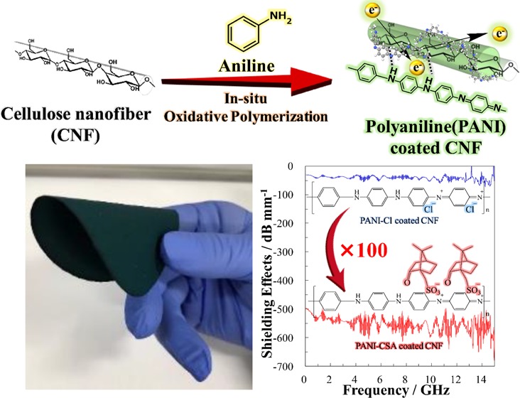
A superior electrical conductivity of 38.5 S/cm and an electromagnetic shielding (EMS) effectiveness of −30 dB (−545 dB/mm) across a wide frequency range of 0–15 GHz, including the X-band, were achieved with thin organic paper of (55 μm) cellulose nanofiber (CNF)/polyaniline (PANI) doped with (±)-10-camphorsulfonic acid nanohybrid. Both electrical conductivity and EMS effectiveness of the PANI-coated CNF were strongly affected by the amount and type of dopant, which could be tunable after fabrication process via simple in situ oxidative polymerization of aniline. Flexible and free-standing film was obtained, since CNF provides good mechanical property without diminishing the electrical property of PANI.
1. Introduction
Electromagnetic shielding (EMS) material is becoming increasingly important for achieving proper use of electronic devices and communication systems.1−5 Electromagnetic waves produced by electronic devices using the radio frequency band can damage human health6,7 or interfere with the proper use of other devices; therefore, they are considered a serious issue. Thus, effective EMS materials that can operate over a wide range of frequencies are required.8 Furthermore, flexible and lightweight EMS materials are better suited to be used in wearable devices.6,7,9−11 Metals, magnetic particles,12−15 and carbon materials16−20 have been widely applied as EMS materials, but these present difficulties with processing and colorability. These problems can be overcome by producing EMS materials made of completely organic components.21−25 Conductive polymers are organic materials that are particularly promising for use in EMS applications.26−28 Aliphatic conductive polymers such as polyacetylene have extremely high electrical conductivity but are unstable under atmospheric conditions. However, aromatic conductive polymers such as polyaniline (PANI) or polypyrrole (PPy), while atmospherically stable, have lower electrical conductivity than that of polyacetylene.29 Therefore, these have been used in applications such as batteries,30,31 EMS materials,32,33 actuators,34 sensors,35,36 and organic thermoelectric materials.37,38
PANI is a typical conductive polymer that is easily synthesized at low cost with good environmental stability.39 However, to achieve the required high electrical conductivity, conductive polymers require a dopant such as hydrochloric, sulfuric, or toluenesulfonic acid. A specific feature of PANI that distinguishes it from other conductive polymers is the tunability of its electrical conductivity. This is because some of its associated dopants are easily detached and exchanged,28 allowing the electrical conductivity to be adjusted by detaching the dopant species to transform from the conductive emeraldine salt to the insulating emeraldine base.40 Unfortunately, PANI is rigid and brittle, so that PANI films are relatively fragile.41 To overcome this problem and achieve superior mechanical properties and processability, PANI composites have been blended with other polymeric materials.42
One such material, cellulose nanofiber (CNF), with a fiber diameter below 100 nm, is attracting much attention as a filler for polymer composites due to its excellent mechanical properties.43,44 CNF, obtained from cellulose, is the most abundant natural resource on earth; due to its good biocompatibility, biodegradability, and hydrophilicity,45,46 it is currently used as a thickener in food and paints. Recent studies have reported composites of CNF and conductive polymers such as PANI and PPy.47−50 Nanocellulose-based conductive polymer composites were produced by simply coating the CNF surface or hybridizing within the polymer network.51
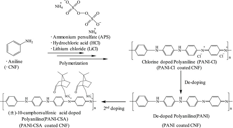
The most popular method of fabricating CNF conductive polymer composites is in situ oxidative polymerization, which initiates monomer polymerization by adding an oxidizing agent to a solution containing well-dispersed CNF. In this study, we fabricated CNF/PANI nanocomposites (Scheme 1) possessing superior electrical properties via in situ oxidative polymerization. Previously, several studies reported CNF/PANI nanocomposites and their application to EMS materials. Marins et al.52 reported an EMS effectiveness of −5 dB in the X-band with an 80 μm thick film. Gopakumar et al.41 indicated that the EMS effectiveness could be improved to −23 dB in the X-band with a paper thickness of 1 mm. However, to be commercially viable in electronic devices, a higher EMS effectiveness is required. Therefore, EMS effectiveness as a function of paper thickness needs to be further improved to match that of other carbon-based composites.16,18,19
Scheme 1. Preparation of CNF/PANI Nanocomposites by Oxidative Polymerization of Aniline.
In this study, the electrical conductivity and EMS efficiency of the CNF/PANI nanocomposites were tuned by exchanging the dopant species to achieve unprecedented efficiencies. To the best of our knowledge, this is the first study that has used the CNF/PANI nanocomposite to achieve an EMS effectiveness of −30 dB over a wide range of frequencies, including the X-band. The tuned CNF/PANI nanocomposite is a breakthrough that will pave the way to commercial application in flexible and wearable electronic devices.
2. Results and Discussion
2.1. Preparation of PANI-Coated CNFs
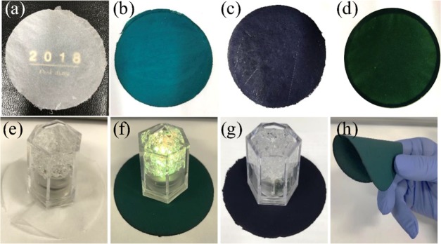
PANI-coated CNFs were prepared via a stepwise process from pristine CNF to PANI–Cl-coated CNF, dedoped-PANI-coated CNF, and finally PANI–CSA-coated CNF. Figure 1 shows color images of pristine CNF and PANI-coated CNF papers with/without dopants. The appearance of the PANI/CNF paper clearly changed after each the modification step from blue to violet to green with Cl doping, dedoping, and (±)-10-camphorsulfonic acid (CSA) doping, respectively. These color changes clearly reflect exchanges of dopant species. The PANI/CNF papers retained the excellent flexibility and foldability of the pristine CNF paper.
Figure 1.
Color images of (a) freeze-dried CNF, (b) PANI–Cl-coated CNF, (c) dedoped-PANI-coated CNF, and (d) PANI–CSA-coated CNF; (e) demonstration of electrical conductivity on the paper surface of freeze-dried CNF: unilluminated, (f) PANI–Cl-coated CNF: illuminated, (g) dedoped-PANI-coated CNF: unilluminated, and (h) demonstration of flexibility of PANI–CSA-coated CNF.
During modification, a small amount of PANI coating on the CNF surface was peeled off as shown in Table 1. The PANI-dopant contents of the PANI-coated CNFs were calculated using eq 1.48
| 1 |
Although the PANI–Cl-coated CNF contained 62.0 wt % PANI–Cl, after detaching the Cl anion in ammonium solution, the PANI-dopant content decreased to 45.0 wt %. Moreover, after CSA doping, the PANI–CSA content decreased to 34.3 wt %, suggesting the desorption of PANI–CSA due to a weak interaction between PANI–CSA and the CNF surfaces.
Table 1. PANI-Dopant Content of CNF Coated with PANI–Cl, PANI, and PANI–CSA.
| sample | PANI-dopant content (wt %) |
|---|---|
| PANI–Cl-coated CNF | 62.0 ± 1.1 |
| dedoped-PANI-coated CNF | 45.0 ± 2.0 |
| PANI–CSA-coated CNF | 34.3 ± 1.6 |
2.2. Morphological Changes of CNF after PANI Coating
Figure 2 shows morphological changes in CNF and the distribution of N obtained by scanning electron microscopy–energy-dispersive X-ray spectrometry (SEM–EDS) of PANI–Cl-coated CNF, PANI-coated CNF, and PANI–CSA-coated CNF. Surface modification of CNF by PANI via in situ polymerization was confirmed by EDS mapping, since N derived from aniline was predominantly observed on the CNF surface. Small nanoscale particles of PANI were observed on the CNF surface (Figure 2a). However, while exchanging the dopant species with CSA, these disappeared (Figure 2c). The surface of the PANI–CSA-coated CNF was uniformly smooth; however, N was observed on its surface (Figure 2c,f). This is due to mechanical detachment of PANI during stirring for dedoping in the ammonium solution and being partially soluble in m-cresol53 during the CSA-doping step, resulting in the formation of a homogeneous layer by recoating and associated weight loss as indicated in Table 1.
Figure 2.
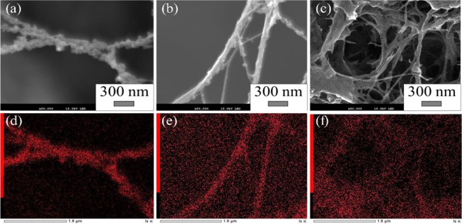
SEM–EDS (N) images of (a, d) PANI–Cl-coated CNF, (b, e) PANI-coated CNF, and (c, f) PANI–CSA-coated CNF.
It is important to understand the interaction between the conductive polymers and the CNF surface in the composites.51 The affinity between these polymeric materials could be increased via multiple hydrogen bondings between the −NH and–OH groups of PANI and the CNF surface, respectively, to cause the recoated PANI on the CNF surface to form a smooth and uniform layer.
2.3. Chemical Structures of PANI-Coated CNFs
PANI–CSA-coated CNF paper was characterized by Fourier transform infrared (FT-IR), as shown in Figure 3, and compared with pristine CNF and free PANI–CSA. Pristine CNF showed a strong absorption peak at 3347 cm–1, assigned to νOH. Other peaks at 2899, 1656, 1438, 1370, 1028, and 899 cm–1 are attributed to νCH, δCH,in-plane, δOCH,in-plane, δCH,out-of-plane, νC–O–C, and vibration of anomeric carbon (C1), respectively.41,54 As regards PANI, peaks observed around 1550, 1470, 1290, and 802 cm–1 are attributed to νC=C,quinoid, νC=C,benzene ring, νCH,secondary amine, and δCH,benzene ring, respectively.55,56 The peak at 1140 cm–1 was attributed to the δCH vibration of the “electronic-like band” and is considered to be a measure of the degree of electron delocalization. Therefore, it is a characteristic peak of PANI conductivity.57,58
Figure 3.
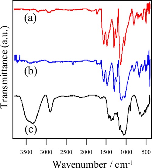
FT-IR spectra of (a) PANI–CSA-coated CNF, (b) free PANI–CSA, and (c) pristine CNF.
Dopant attachment was confirmed by a characteristic peak at 1730 cm–1, specific to νC=O of CSA in the spectra of free PANI–CSA and PANI–CSA-coated CNF.55
2.4. Mechanical Properties of PANI-Coated CNFs
The mechanical properties of PANI-coated CNFs after tensile tests (stress–strain curves are shown in Figure S2) are summarized in Table 2. Drastic deterioration of the mechanical properties such as the tensile strength and the Young’s modulus was observed when CNF was coated with rigid PANI. These results were consistent with the previous reports,49,52 and reduced hydrogen-bond formation between cellulose microfibrils due to surface modification by PANI was considered to explain the deterioration in mechanical properties.53 The PANI–CSA-coated CNF showed better mechanical properties than the PANI–Cl-coated CNF. This could be due to a decrease in the PANI content by elution when changing the dopant using m-cresol. CNF was considered to be a suitable support for improving the mechanical properties of composites with conductive polymers, which are generally fragile and rigid.
Table 2. Mechanical Properties of Modified CNF Paper.
| sample | tensile strength (MPa) | Young’s modulus (GPa) | maximum elongation (%) | strain energy (J/m3) |
|---|---|---|---|---|
| CNF | 74.9 ± 11.6 | 2.6 ± 1.9 | 12.7 ± 2 | 5.0 ± 1.2 |
| PANI–Cl-coated CNF | 4.9 ± 0.9 | 0.5 ± 0.4 | 5.6 ± 1.7 | 0.2 ± 0.1 |
| PANI–CSA-coated CNF | 15.6 ± 3.3 | 1.4 ± 1.5 | 4.8 ± 0.3 | 0.4 ± 0.1 |
2.5. Electrical Conductivity of PANI-Coated CNFs
The electrical conductivity and resistivity of the PANI-coated CNF papers are summarized in Table 3. The electrical conductivity of pristine CNF was relatively low, 7.34 × 10⁻¹³ S/cm. However, the electrical conductivity of the PANI–Cl-coated CNF rose steeply to 0.20 S/cm. Significantly, this value was considerably higher than those previously reported for the CNF/PANI composites within the range 10–4 to 100 S/cm (Table S3 in the Supporting Information). Surprisingly, the electrical conductivity of the PANI–CSA-coated CNF reached 38.5 S/cm, which was 193 times higher than that of the PANI–Cl-coated CNF. To the best of our knowledge, this is the highest electrical conductivity ever reported for the CNF/PANI composites.
Table 3. Resistivity and Electrical Conductivity of CNF, PANI–Cl-Coated CNF, and PANI–CSA-Coated CNF.
| sample | thickness (μm) | surface resistivity (Ω/sq) | volume resistivity (Ω cm) | electrical conductivity (S/cm) |
|---|---|---|---|---|
| CNF | 35.1 ± 3.5 | 2.7 × 10¹³ | 1.40 × 10¹² | 7.34 × 10⁻¹³ |
| PANI–Cl-coated CNF | 87.5 ± 14.0 | 82.4 ± 1.4 | 5.23 ± 1.49 | 0.20 ± 0.0 |
| PANI–CSA-coated CNF | 54.9 ± 15.8 | 5.3 ± 2.1 | 0.03 ± 0.00 | 38.5 ± 0.8 |
One possible explanation is that because CSA is an excellent dopant for PANI-coated CNF, it enhances the electron transfer to PANI. Moreover, the dopant and solvent combination positively affected the electrical conductivity. It is also known that the electrical conductivity of PANI was drastically changed by the solvent choice. In this study, a structural change from a compact coil to an expanded CSA coil is considered to occur on treatment with a phenol-type solvent, m-cresol, as previously reported.59 Proton exchange between the imine group in PANI and the acid group in the dopant is believed to be promoted by m-cresol, with the efficient removal of protons from the dopant.
The effects of the dopant content on the electrical conductivity and the volume/surface resistivity of the PANI–CSA-coated CNF are shown in Figure S3. The electrical conductivity increased with increase in the CSA dopant content from 0.06 S/cm (0.1 mmol) to a maximum of 38.5 S/cm (0.5 mmol). However, the electrical conductivity decreased when the CSA content was further increased. These results indicated that achieving an optimum dopant content is necessary to achieve high electrical conductivity, since the dopant itself showed no conductivity.
2.6. Electromagnetic Shielding
Theoretically, an electrical conductivity above 10–1 to 1 S/cm is necessary to achieve effective attenuation or shielding from microwaves.60 However, the high conductivity is complemented by the formation of a continuous network and the presence of electric dipoles in PANI/CNF, which further improve the overall shielding effectiveness.41
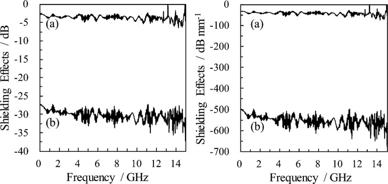
Typical spectra showing the EMS effectiveness of the PANI/CNF nanocomposites are shown in Figure 4a. The effectiveness of the PANI–Cl-coated CNF was only −3 dB, with a paper thickness of 88 μm. Conversely, the PANI–CSA-coated CNF showed an improvement of 2 orders of magnitude in the EMS effectiveness of around −30 dB (97% attenuation) for the 0–15 GHz bandwidth including the X-band (8.2–12.4 GHz), despite using a thinner paper of 55 μm. This excellent EMS shielding effectiveness is equivalent to −545 dB/mm, considering the film thickness, as shown in Figure 4b.
Figure 4.
EMS effects of (a) PANI–Cl-coated CNF paper (thickness: 88 μm) and (b) PANI–CSA-coated CNF paper (thickness: 55 μm) with (right) or without (left) consideration of film thickness.
The correlation between the dopant content and the EMS effectiveness of the PANI–CSA-coated CNF film is shown in Figure S4. The electrical conductivity and the EMS effectiveness obtained with doped PANI-coated CNF at 10 GHz are shown in Figure S4(b). The maximum EMS effectiveness (−30 to −35 dB) was achieved at a dopant concentration of 0.5 mmol, which also showed the highest electrical conductivity, while a lower or higher dopant content did not give superior EMS effectiveness. The EMS effectiveness is shown to be strongly affected by electrical conductivity.61 Thus, both suitable dopant and dopant content are essential for achieving both superior electrical conductivity and EMS effectiveness.
Table 4 summarizes the previously reported completely organic EMS materials. An EMS effectiveness of −5 dB by PANI–Cl/CNF was reported by Marins et al. (no. 1 in Table 4), which was close to the value of −3 dB for no. 8 in Table 4, with the same components, but the attenuation achieved was far from being viable for commercial application to electronic devices.52 However, the improvement in EMS effectiveness achieved by Gopakumar et al.41 to −23 dB in the X-band region for the PANI–Cl-coated CNF with a paper thickness of 1 mm (no. 2) is notable. However, this is not superior to carbon-based composites in terms of thickness and EMS effectiveness, as shown in Table 4, when compared with the results for nos. 3 and 4.16,18,19,41,46,52,62 In contrast to no. 2, PANI–CSA-coated CNF (no. 9, thickness 55 μm) was much thinner and showed superior EMS effectiveness reaching −30 dB (−545 dB/mm) over a wide frequency range of 0–15 GHz, including the X-band; this has, to the best of our knowledge, the highest EMS effectiveness of all organic EMS materials previously reported as shown in Table 4. The decrease in the thickness during the change of dopant was due to a reduction in PANI by dissolution in m-cresol. It is noteworthy that the EMS effectiveness increased despite a decrease in paper thickness for the PANI–CSA-coated CNF paper, whereas the general rule is that EMS effectiveness increases with paper thickness. The increase in EMS effectiveness is consistent with the electrical conductivity spike of 38.5 S/cm, which is 193 times that of the PANI–Cl-coated CNF. An attenuation above 97% could be achieved by an EMS effectiveness exceeding −30 dB. A decrease in the content of PANI, which is fragile and rigid, improved the flexibility of the paper. Hybridization of a tough CNF with PANI–CSA, which has good electrical conductivity, gave a free-standing paper with superior EMS effectiveness over a wide band width including the X-band region.
Table 4. Summary of Previously Reported Totally Organic EMS Materials.
| no. | substrate | conductive materials | thickness (mm) | shielding effect (dB) | frequency (GHz) | references |
|---|---|---|---|---|---|---|
| 1 | BCa | PANI–Cl | 0.080 | –5 | 8.2–12.4 | (52) |
| 2 | CNF | PANI–Cl | 1.0 | –23 | 8.2–12.4 | (41) |
| 3 | CNF | CNT/AgNWse | 0.161 | –25 | 0.5–1.0 | (62) |
| 4 | CNF | rGOf | 0.023 | –26.2 | 8.2–12.4 | (46) |
| 5 | PPb | MWCNTg | 0.340 | –22.3 | 8.2–12.4 | (19) |
| 6 | ABSc | CBh | 1.1 | –22 | 8.2–12.4 | (18) |
| 7 | PSd | rGO | 2.8 | –24 | 8.2–12.4 | (16) |
| 8 | CNF | PANI–Cl | 0.088 | –3 | 0.45–15 | this work |
| 9 | CNF | PANI–CSA | 0.055 | –30 | 0.45–15 | this work |
Bacterial cellulose.
Polypropylene.
Acrylonitrile–butadiene–styrene copolymer.
Polystyrene.
Silver nanowires.
Reduced graphene oxide.
Multiwall carbon nanotube.
Carbon black.
3. Conclusions
The flexible and lightweight PANI/CNF nanocomposites, which were successfully fabricated via in situ oxidative polymerization, appear to show the highest EMS shielding efficiency ever reported. The electrical conductivity and EMS shielding efficiency of PANI were improved by replacing dopant species from HCl with CSA. The PANI–CSA-coated CNF showed the highest electrical conductivity of 38.5 S/cm, which was 193 times higher than that of the PANI–Cl-coated CNF. The choice of dopant and its combination with a solvent having a phenolic component such as m-cresol was significant in the improving electrical conductivity. The PANI–CSA-coated CNF nanocomposite with a paper thickness of only 55 μm achieved an EMS shielding efficiency of −30 dB (−545 dB/mm) across a wide frequency range of 0–15 GHz, including the X-band. The PANI–CSA-coated CNF nanocomposite will be applicable not only to EMS materials but also to capacitors or sensors due to its flexibility and lightweight.
Polymer composites possessing excellent mechanical and electrical properties could be developed by compounding with the PANI–CSA-coated CNF as a masterbatch.
4. Materials and Methods
4.1. Materials
Aniline, ammonium solution (28%), ammonium persulfate (APS), m-cresol, CSA, hydrochloric acid (HCl), and lithium chloride (LiCl) were purchased from WAKO Chemical (Wako, Japan). CNFs in 1% water suspension, produced by an aquatic counter-collision method from bamboo cellulose, were provided by Chuetsu Pulp & Paper Co., Ltd. (Takaoka, Japan) and were used as received.
4.2. Fabrication of PANI-Coated CNF Nanocomposite Paper
A diagram of the fabrication of PANI-coated CNF nanocomposite paper is shown in Figure S1 (Supporting Information). In situ oxidative polymerization of aniline on CNF was conducted under atmospheric conditions. A 10 g sample of 1% CNF gel (100 mg dry weight) was dissolved in 100 mL of 1 M HCl solution together with aniline (1.4 mmol) and LiCl (0.2 mol), and the solution was stirred for 1 h at −10 °C. An oxidizing agent, APS (1.75 mmol) dissolved in water (50 mL), was slowly added over 1 h and stirred for 3 h at −10 °C. The resulting PANI–Cl-coated CNF gel was obtained after filtering with a membrane filter (pore size 1.0 μm) and washing with water and acetone. The PANI–Cl-coated CNF nanocomposite was obtained as a paper of 88 μm thickness after freeze drying at room temperature (RT).
Chlorine ions, as a dopant of the PANI–Cl-coated CNF gel, were detached by soaking in an ammonium solution (1 M, 100 mL) and stirring for 3 h at RT. Consequently, the PANI-coated CNF nanocomposite was obtained after freeze-drying at RT.
Another dopant species, CSA (0.5 mmol), was dissolved in m-cresol (50 mL), added to the PANI-coated CNF gel/ammonium solution, and stirred for 3 h at RT to attach CSA as a dopant. The PANI–CSA-coated CNF gel was obtained after centrifugation (5000 rpm, 10 min) followed by vacuum filtration and washing with acetone. Finally, the PANI–CSA-coated CNF nanocomposite was obtained as a paper of 55 μm thickness after freeze-drying at RT.
Free PANI–CSA was prepared in a similar manner from free PANI and CSA without CNF.
4.3. Characterization
The morphologies of the modified CNF and freeze-dried pristine CNF were observed using field emission scanning electron microscopy–energy-dispersive X-ray spectroscopy (FE-SEM/EDS) (JSM-7800F, JEOL, Tokyo, Japan) at an accelerating voltage of 15 kV with an electron conductive gold layer.
The chemical structures of the CNF/PANI nanocomposites were analyzed by FT-IR spectroscopy, using a Nicolet iZ10 attached SMART iTR instrument (Thermo Fisher Scientific, Tokyo, Japan), in the wavenumber range 400–4000 cm–1 at a resolution of 4 cm–1. Transmission spectra were measured using a KBr disk blended with each sample.
4.4. Electrical Properties
The electrical conductivity was measured at 23 ± 2 °C by a four-point probe method with a low-resistance meter (Loresta MCP-T410, Mitsubishi Chemical Corporation, Kanagawa, Japan). The samples for measurement were prepared in sizes of 4 × 16 mm2 from various PANI-coated CNF papers, whose thicknesses were measured using a digital micrometer (PG-01, Teclock Corporation, Nagano, Japan) with a resolution of 1 μm.
The EMS effectiveness of each sample was evaluated at 23 ± 2 °C in the frequency range 0.45–15 GHz, including G-, S-, and X-bands, with a network analyzer (MS202C, Anritsu Corporation, Kanagawa, Japan) and a coaxial tube-type shield-effect measurement system (SEM01 KEYCOM, Tokyo, Japan).
Acknowledgments
Authors would like to thank Dr Takayuki Tsukegi from Kanazawa Institute of Technology for technical support in sample preparation.
Supporting Information Available
The Supporting Information is available free of charge on the ACS Publications website at DOI: 10.1021/acsomega.9b00708.
Fabrication processes of the PANI–CSA-coated CNF paper; contact angle values of pristine CNF, modified CNF with PANI–Cl, PANI, and PANI–CSA; assignments of the main peaks in the FTIR spectra of CNF, PANI(−Cl, −CSA), and PANI(−Cl, −CSA)-coated CNF; effect of the dopant amount on electrical properties of the PANI–CSA-coated CNF; NCs and polyaniline hybrids conductivity; effect of dopant amount on EMS properties of PANI–CSA-coated CNF (PDF)
Author Present Address
† Science of Polymeric Materials, Department of Biomaterial Sciences, Graduate School of Agricultural and Life Sciences, The University of Tokyo, 1-1-1 Yayoi, Bunkyo-ku, Tokyo 113-8657, Japan (T.O.).
The authors declare no competing financial interest.
Supplementary Material
References
- Liu P.; Huang Y.; Yan J.; Yang Y.; Zhao Y. Construction of CuS Nano flakes vertically aligned on magnetically decorated graphene and their enhanced microwave absorption properties. ACS Appl. Mater. Interfaces 2016, 8, 5536–5546. 10.1021/acsami.5b10511. [DOI] [PubMed] [Google Scholar]
- Jalali M.; Dauterstedt S.; Michaud A.; Wuthrich R. Electromagnetic shielding of polymer-matrix composites with metallic nanoparticles. Composites, Part B 2011, 42, 1420–1426. 10.1016/j.compositesb.2011.05.018. [DOI] [Google Scholar]
- Ling J.; et al. Facile preparation of lightweight microcellular polyetherimide/graphene composite foams for electromagnetic interference shielding. ACS Appl. Mater. Interfaces 2013, 5, 2677–2684. 10.1021/am303289m. [DOI] [PubMed] [Google Scholar]
- Yan D.-X.; et al. Efficient electromagnetic interference shielding of lightweight graphene/polystyrene composite. J. Mater. Chem. 2012, 22, 18772–18774. 10.1039/c2jm32692b. [DOI] [Google Scholar]
- Shen B.; Zhai W.; Tao M.; Ling J.; Zheng W. Lightweight, multifunctional polyetherimide/graphene @ Fe 3 O 4 composite foams for shielding of electromagnetic pollution. ACS Appl. Mater. Interfaces 2013, 5, 11383–11391. 10.1021/am4036527. [DOI] [PubMed] [Google Scholar]
- Chung D. D. L. Electromagnetic interference shielding effectiveness of carbon materials. Carbon 2001, 39, 279–285. 10.1016/S0008-6223(00)00184-6. [DOI] [Google Scholar]
- Das A.; et al. Superhydrophobic and conductive carbon nanofiber/PTFE composite coatings for EMI shielding. J. Colloid Interface Sci. 2011, 353, 311–315. 10.1016/j.jcis.2010.09.017. [DOI] [PubMed] [Google Scholar]
- Zhang Y.-G.; et al. Binary strengthening and toughening of mxene/cellulose nanofiber composite paper with nacre-inspired structure and superior electromagnetic interference shielding properties. ACS Nano 2018, 12, 4583–4593. 10.1021/acsnano.8b00997. [DOI] [PubMed] [Google Scholar]
- Yang Y.; Gupta M. C.; Dudley K. L.; Lawrence R. W. Novel carbon nanotube – polystyrene foam composites for electromagnetic interference shielding. Nano Lett. 2005, 5, 2131–2134. 10.1021/nl051375r. [DOI] [PubMed] [Google Scholar]
- Chen Z.; Xu C.; Ma C.; Ren W.; Cheng H. Lightweight and flexible graphene foam composites for high-performance electromagnetic interference shielding. Adv. Mater. 2013, 25, 1296–1300. 10.1002/adma.201204196. [DOI] [PubMed] [Google Scholar]
- Song W.-L.; et al. Magnetic and conductive graphene papers toward thin layers of effective electromagnetic shielding. J. Mater. Chem. A 2015, 3, 2097–2107. 10.1039/C4TA05939E. [DOI] [Google Scholar]
- Kim S. W.; et al. Electromagnetic shielding properties of soft magnetic powder–polymer composite films for the application to suppress noise in the radio frequency range. J. Magn. Magn. Mater. 2007, 316, 472–474. 10.1016/j.jmmm.2007.03.133. [DOI] [Google Scholar]
- Zhou W.; et al. Synthesis and Electromagnetic, Microwave absorbing properties of core _ shell Fe 3 O 4 _ poly(3, 4-ethylenedioxythiophene) microspheres. ACS Appl. Mater. Interfaces 2011, 3, 3839–3845. 10.1021/am2004812. [DOI] [PubMed] [Google Scholar]
- Li W.; et al. Preparation and electromagnetic properties of core/shell polystyrene @ polypyrrole @ nickel composite microspheres. ACS Appl. Mater. Interfaces 2013, 5, 883–891. 10.1021/am302551d. [DOI] [PubMed] [Google Scholar]
- Cao M.; et al. Ferroferric oxide/multiwalled carbon nanotube vs polyaniline/ferroferric oxide/multiwalled carbon nanotube multiheterostructures for highly effective microwave absorption. ACS Appl. Mater. Interfaces 2012, 4, 6949–6956. 10.1021/am3021069. [DOI] [PubMed] [Google Scholar]
- Li C.; et al. The preparation and properties of polystyrene/functionalized graphene nanocomposite foams using supercritical carbon dioxide. Polym. Int. 2012, 62, 1077–1084. 10.1002/pi.4394. [DOI] [Google Scholar]
- Zhang H.; Zheng W.; Yan Q.; Jiang Z.-G.; Yu Z.-Z. The effect of surface chemistry of graphene on rheological and electrical properties of polymethylmethacrylate composites. Carbon 2012, 50, 5117–5125. 10.1016/j.carbon.2012.06.052. [DOI] [Google Scholar]
- Al-Saleh M. H.; Saadeh W. H.; Sundararaj U. EMI shielding effectiveness of carbon based nanostructured polymeric materials: A comparative study. Carbon 2013, 60, 146–156. 10.1016/j.carbon.2013.04.008. [DOI] [Google Scholar]
- Al-Saleh M. H.; Sundararaj U. Electromagnetic interference shielding mechanisms of CNT/polymer composites. Carbon 2009, 47, 1738–1746. 10.1016/j.carbon.2009.02.030. [DOI] [Google Scholar]
- Li N.; et al. Electromagnetic Interference (EMI) shielding of single-walled carbon nanotube epoxy composites. Nano Lett. 2006, 6, 1141–1145. 10.1021/nl0602589. [DOI] [PubMed] [Google Scholar]
- Niu Y. Preparation of polyaniline/polyacrylate composites and their application for electromagnetic interference. Polym. Compos. 2006, 27, 627–632. 10.1002/pc.20245. [DOI] [Google Scholar]
- Pomposo J. A.; Rodrıguez J.; Grande H. Polypyrrole-based conducting hot melt adhesives for EMI shielding applications. Synth. Met. 1999, 104, 107–111. 10.1016/S0379-6779(99)00061-2. [DOI] [Google Scholar]
- Kim B. R.; Lee H. K.; Park S. H.; Kim H. K. Electromagnetic interference shielding characteristics and shielding effectiveness of polyaniline-coated films. Thin Solid Films 2011, 519, 3492–3496. 10.1016/j.tsf.2011.01.093. [DOI] [Google Scholar]
- Tantawy H. R.; Aston D. E.; Smith J. R.; Young L. Comparison of electromagnetic shielding with polyaniline nanopowders produced in solvent-limited conditions. ACS Appl. Mater. Interfaces 2013, 5, 4648–4658. 10.1021/am401695p. [DOI] [PubMed] [Google Scholar]
- Onar N.; et al. Structural, electrical, and electromagnetic properties of cotton fabrics coated with polyaniline and polypyrrole. J. Appl. Polym. Sci. 2009, 114, 2003–2010. 10.1002/app.30652. [DOI] [Google Scholar]
- Fauveaux S.; Miane J.-L. Broadband electromagnetic shields using polyaniline composites. Electromagnetics 2003, 23, 617–627. 10.1080/02726340390244734. [DOI] [Google Scholar]
- Colaneri N. F.; Shacklette L. W. EMI Shielding measurements of conductive polymer blends. IEEE Trans. Instrum. Meas. 1992, 41, 291–297. 10.1109/19.137363. [DOI] [Google Scholar]
- Dhawan S. K.; Singha N.; Rodrigues D. Electromagnetic shielding behaviour of conducting polyaniline composites. Sci. Technol. Adv. Mater. 2003, 4, 105–113. 10.1016/S1468-6996(02)00053-0. [DOI] [Google Scholar]
- Toshima N.; Imai M.; Ichikawa S. Organic–inorganic nanohybrids as novel thermoelectric materials: Hybrids of polyaniline and bismuth (III) telluride nanoparticles. J. Electron. Mater. 2011, 40, 898–902. 10.1007/s11664-010-1403-1. [DOI] [Google Scholar]
- Zhao Z.; Yu T.; Miao Y.; Zhao X. Chloride ion-doped polyaniline/carbon nanotube nanocomposite materials as new cathodes for chloride ion battery. Electrochim. Acta 2018, 270, 30–36. 10.1016/j.electacta.2018.03.077. [DOI] [Google Scholar]
- Zhao H.; et al. Mussel-inspired conductive polymer binder for si-alloy anode in lithium-ion batteries. ACS Appl. Mater. Interfaces 2018, 10, 5440–5446. 10.1021/acsami.7b14645. [DOI] [PubMed] [Google Scholar]
- He W.; Li J.; Tian J.; Jing H.; Li Y. Characteristics and properties of wood/polyaniline electromagnetic shielding composites synthesized via in situ polymerization. Polym. Compos. 2018, 39, 537–543. 10.1002/pc.23966. [DOI] [Google Scholar]
- Yu D.; Wang Y.; Hao T.; Wang W.; Liu B. Preparation of silver- plated polyimide fabric initiated by polyaniline with electromagnetic shielding properties. J. Ind. Text. 2018, 47, 1392–1406. 10.1177/1528083717692592. [DOI] [Google Scholar]
- Zhang Y. Y.; et al. Preparation and properties of core-shell structured calcium copper titanate@polyaniline/silicone dielectric elastomer actuators. Polym. Compos. 2019, 40, E62–E68. 10.1002/pc.24479. [DOI] [Google Scholar]
- Gao J.; et al. Electrically conductive polymer nano fiber composite with an ultralow percolation threshold for chemical vapour sensing. Compos. Sci. Technol. 2018, 161, 135–142. 10.1016/j.compscitech.2018.04.014. [DOI] [Google Scholar]
- Lin C. W.; Hwang B. J.; Lee C. R. Methanol sensors based on the conductive polymer composites from polypyrrole and poly (vinyl alcohol). Mater. Chem. Phys. 1998, 55, 139–144. 10.1016/S0254-0584(98)00087-X. [DOI] [Google Scholar]
- Hata S.; et al. Novel Preparation of Poly(3,4-ethylenedioxythiophene)-poly(styrenesulfonate)- protected noble metal nanoparticles as organic-inorganic hybrid thermoelectric materials. Bull. Soc. Photogr. Imaging 2017, 27, 13–18. [Google Scholar]
- Shiraishi Y.; et al. Improved thermoelectric behavior of poly(3,4-ethylenedioxythiophene)-poly(styrenesulfonate) using poly(n-vinyl-2-pyrrolidone)-coated geo2 nanoparticles. Chem. Lett. 2017, 46, 933–936. 10.1246/cl.170218. [DOI] [Google Scholar]
- Falletta E.; Costa P.; Della Pina C.; Lanceros-Mendez S. Development of high sensitive polyaniline based piezoresistive films by conventional and green chemistry approaches. Sens. Actuators, A 2014, 220, 13–21. 10.1016/j.sna.2014.09.004. [DOI] [Google Scholar]
- Shigeyoshi M. Corrosion protection of metals by conductive polymer polyaniline. J. Jpn. Soc. Colour Mater. 2012, 85, 240–248. 10.4011/shikizai.85.240. [DOI] [Google Scholar]
- Gopakumar D. A.; et al. Cellulose nanofiber-based polyaniline flexible papers as sustainable microwave absorbers in the X - band. ACS Appl. Mater. Interfaces 2018, 10, 20032–20043. 10.1021/acsami.8b04549. [DOI] [PubMed] [Google Scholar]
- Jia Q. M.; Li J. B.; Wang L. F.; Zhu J. W.; Zheng M. Electrically conductive epoxy resin composites containing polyaniline with different morphologies. Mater. Sci. Eng. A 2007, 448, 356–360. 10.1016/j.msea.2006.09.065. [DOI] [Google Scholar]
- Casado U. M.; Aranguren M. I.; Marcovich N. E. Preparation and characterization of conductive nanostructured particles based on polyaniline and cellulose nanofibers. Ultrason. Sonochem. 2014, 21, 1641–1648. 10.1016/j.ultsonch.2014.03.012. [DOI] [PubMed] [Google Scholar]
- Lee B.; Kim H.; Yang H. Polymerization of aniline on bacterial cellulose and characterization of bacterial cellulose/polyaniline nanocomposite films. Curr. Appl. Phys. 2012, 12, 75–80. 10.1016/j.cap.2011.04.045. [DOI] [Google Scholar]
- Sajab M. S.; et al. Bifunctional graphene oxide-cellulose nanofibril aerogel loaded with Fe(III) for removal of cationic dye via simultaneous adsorption and Fenton oxidation. RSC Adv. 2016, 6, 19819–19825. 10.1039/C5RA26193G. [DOI] [Google Scholar]
- Yang W.; et al. Ultrathin flexible reduced graphene oxide/cellulose nanofiber composite films with strongly anisotropic thermal conductivity and efficient. J. Mater. Chem. C 2017, 5, 3748–3756. 10.1039/C7TC00400A. [DOI] [Google Scholar]
- Wang H.; Bian L.; Zhou P.; Tang J.; Tang W. Core–sheath structured bacterial cellulose/polypyrrole nanocomposites with excellent conductivity as supercapacitors. J. Mater. Chem. A 2013, 1, 578–584. 10.1039/C2TA00040G. [DOI] [Google Scholar]
- Lin Z.; Guan Z.; Huang Z. New bacterial cellulose/polyaniline nanocomposite film with one conductive side through constrained interfacial polymerization. Ind. Eng. Chem. Res. 2013, 52, 2869–2874. 10.1021/ie303297b. [DOI] [Google Scholar]
- Hu W.; Chen S.; Yang Z.; Liu L.; Wang H. Flexible electrically conductive nanocomposite membrane based on bacterial cellulose and polyaniline. J. Phys. Chem. B 2011, 115, 8453–8457. 10.1021/jp204422v. [DOI] [PubMed] [Google Scholar]
- Tang L.; Han J.; Jiang Z.; Chen S.; Wang H. Flexible conductive polypyrrole nanocomposite membranes based on bacterial cellulose with amphiphobicity. Carbohydr. Polym. 2015, 117, 230–235. 10.1016/j.carbpol.2014.09.049. [DOI] [PubMed] [Google Scholar]
- Du X.; Zhang Z.; Liu W.; Deng Y. Nanocellulose-based conductive materials and their emerging applications in energy devices-A review. Nano Energy 2017, 35, 299–320. 10.1016/j.nanoen.2017.04.001. [DOI] [Google Scholar]
- Marins J. A.; Soares B. G.; Fraga M.; Müller D.; Barra G. M. O. Self-supported bacterial cellulose polyaniline conducting membrane as electromagnetic interference shielding material: Effect of the oxidizing agent. Cellulose 2014, 21, 1409–1418. 10.1007/s10570-014-0191-9. [DOI] [Google Scholar]
- Cao Y.; Smith P.; Alan J. H. Counter-ion induced processibility of conducting polyaniline and of conducting polyblends of polyaniline in bulk polymers. Synth. Met. 1992, 48, 91–97. 10.1016/0379-6779(92)90053-L. [DOI] [Google Scholar]
- Silva M. J.; et al. Conductive nanocomposites based on cellulose nanofibrils coated with polyaniline-dbsa via in situ polymerization. Macromol. Symp. 2012, 319, 196–202. 10.1002/masy.201100156. [DOI] [Google Scholar]
- Falletta E.; Costa P.; Della Pina C.; Lanceros-Mendez S. Development of high sensitive polyaniline based piezoresistive films by conventional and green chemistry approaches. Sens. Actuators, A 2014, 220, 13–21. 10.1016/j.sna.2014.09.004. [DOI] [Google Scholar]
- Chen Z.; Della C.; Falletta E.; Rossi M. A green route to conducting polyaniline by copper catalysis. J. Catal. 2009, 267, 93–96. 10.1016/j.jcat.2009.07.007. [DOI] [Google Scholar]
- Quillard S.; Louarn G.; Lefrant S.; Macdiarmid A. G. Vibrational analysis of polyaniline: A comparative study of leucoemeraldine, emeraldine, and pernigraniline bases. Phys. Rev. B 1994, 50, 12496 10.1103/PhysRevB.50.12496. [DOI] [PubMed] [Google Scholar]
- Quillard S.; et al. Vibrational spectroscopic studies of the isotope effects in polyaniline. Synth. Met. 1997, 84, 805–806. 10.1016/S0379-6779(96)04155-0. [DOI] [Google Scholar]
- Xia Y.; Wiesinger J. M.; Macdiarmid A. G.; Epstein A. J. Camphorsulfonic acid fully doped polyaniline emeraldine salt: Conformations in different solvents studied by an ultraviolet/visible/near-infrared spectroscopic method. Chem. Mater. 1995, 7, 443–445. 10.1021/cm00051a002. [DOI] [Google Scholar]
- Dhakate S. R.; Subhedar K. M.; Singh B. P. Polymer nanocomposite foam filled with carbon nanomaterials as an efficient electromagnetic interference shielding material. RSC Adv. 2015, 5, 43036–43057. 10.1039/C5RA03409D. [DOI] [Google Scholar]
- Hatakeyama K.; Iot T. T. Study on electromagnetic wave absorbing and shielding material using artificially designed material. J. Inst. Electron., Inf. Commun. Eng. 2017, J100-B, 127–137. [Google Scholar]
- Choi H. Y.; Lee T.; Lee S.; Lim J.; Gyu Y. Silver nanowire/carbon nanotube/cellulose hybrid papers for electrically conductive and electromagnetic interference shielding elements. Compos. Sci. Technol. 2017, 150, 45–53. 10.1016/j.compscitech.2017.07.008. [DOI] [Google Scholar]
Associated Data
This section collects any data citations, data availability statements, or supplementary materials included in this article.


