Abstract
In this study, we report, for the first time, the synthesis of two original nanosystems, based on gold Au(III) and copper Cu(II): simple gold–copper nanoparticles (Cu0AuNPs) and enriched monopicolinate cyclam (L1)–Cu(II)–Au(III)-complex (L1@Cu2+AuNPs). The two nanomaterials differ substantially by the chelation or not of the Cu(II) ions during the NPs synthesis process. The two hybrid nanoparticles (Cu0AuNPs; L1@Cu2+AuNPs) were deeply studied from the chemical and physical point of view, using many different analytical techniques such as Raman and UV–vis spectroscopy, electron transmission microscopy, and dynamic light scattering. Both nanosystems show morphological and good chemical stability at pH 4 values and in physiological conditions during 98 h. Undifferentiated and neural differentiated murine embryonic stem cells were used as a model system for in vitro experiments to reveal the effects of NPs on these cells. The comparative study between Cu0AuNPs and L1@Cu2+AuNPs highlights that copper chelated in its +2 oxidation state in the NPs is more functional for biological application.
1. Introduction
Hybrid metal–organic nanoparticles (NPs) have been recently used as diagnostic and therapeutic tools to better understand, detect, and treat several human diseases.1,2 Metal-based NPs have been proposed as performing contrast agents that can increase signal intensity in magnetic resonance imaging (MRI) and positron emission tomography imaging, or as nanovectors for specifically delivering of drugs inside cells.
The insertion of copper (Cu), especially as Cu2+ atoms, in NPs structures is still challenging because it has an important impact in many scientific fields from catalysis and plasmonics up to nanomedicine applications.3−6 Because cationic metals take part in biological systems (charge balancing, stabilizing structures, reactions catalyzing, and so on), copper ions should be chelated to avoid the in vivo metal releasing that could induce several undesirable effects.
Biocompatible copper(II) chelators are commonly those that yield thermodynamically stable and kinetically inert complexes so that transchelation of Cu due to competition with other biological ligands, metals, or reductive media is avoided. Among known copper(II) ligands, azacycloalkanes present the highest complexion properties.7 By N-functionalization of their properties, especially in terms of kinetic of formation (maximizing the complexation rate) and dissociation (decreasing of the decomplexation rate), could also be improved. A special category of rigid tetraazamacrocycles, indicated as cross-bridged derivatives, has been the source of great interest because of the outstanding behavior in complexing different metals, including copper(II).8−10 Due to an ethylene linker connecting two opposite nitrogen atoms of the macrocycle, these ligands produced some of the most inert metal complexes ever reported.
We recently have published a size-adapted azamacrocycle, the cb-te1pa chelator11−13 (see its structure in Figure 1), which combines all the criteria for Cu(II) chelation, i.e., the presence of cyclam, the ethylene cross bridge and an efficient chelating functionalization, in particular the methyl pycolinic acid, a cross-bridged cyclam bearing a methylpycolinate pendant. This compound was able to chelate copper(II) after fast complexation, yielding a highly thermodynamical stable and an exceptionally inert product, even if Cu was in the (+1) oxidation state. Due to the presence of a secondary amine, an additional functional group, which could be dedicated to the conjugation of cb-te1pa with a solid support, was then easily added as an aniline moiety. To preserve a sufficient distance between the coordination center and the anchoring point, an ethylene linker was chosen to take away the aromatic part. The bifunctionalized analogue cb-te1pa-EtpPhNH2 (L1) was then the final Cu ligand (Figure 1).
Figure 1.
Ligand cb-te1pa and its bifunctionalized analogue cb-te1pa-EtpPhNH2.
In the present study, we synthesized two new nanoparticle systems including gold and copper wrapped in their structure. In the first case, Cu(II) was introduced as “free” cation and in the second case, in its [Cu(cb-te1pa)]+-EtpPhNH2 chelated form (L1Cu+). According to the NPs formation procedure, the first material included Cu0, whereas the second one the Cu2+ chelated ions. Characterizations were performed to investigate the structure of both NPs. Potential cytotoxic effects was evaluated in vitro on undifferentiated and neural differentiated embryonic stem cells (ESCs). ESCs can be used as a model system in basic research, drug discovery, biomedical applications, and nanotechnology because they combine the potential of unlimited self-renewal with the ability to differentiate into a wide range of tissue-specific cells.
2. Results and Discussion
2.1. Formation Mechanisms of Au–Cu-Based Nanoparticles
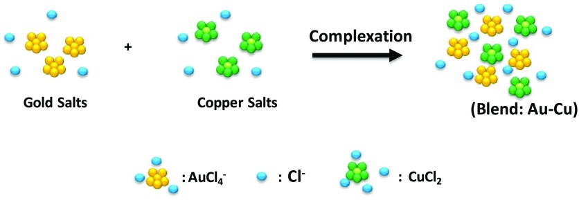
Peculiar molecular interactions between organic compounds and metal chlorides was extensively studied for many biochemical and physical applications.19−22 The aim of this study was to use a copper–gold chloride blend as the building blocks of hybrid nanoparticles under specific conditions of reaction. For this purpose, in the first step, we mixed HAuCl4·3H2O and CuCl2·6H2O in water solution at room temperature under specific pH conditions (Scheme 1). The formation of Au–Cu blend (Figure S1 in the Supporting Information) could be deduced by looking at the fingerprints of each single solution (HAuCl4·3H2O, CuCl2·6H2O) present in the UV–vis spectrum of their mix (Au–Cu). In particular, the UV–vis spectrum of HAuCl4·3H2O (black line in Figure S1) showed typical signatures with two prominent peaks at 256 and 290 nm. The UV–vis spectrum of CuCl2·6H2O solution showed a peak at 256 nm, a small peak at 280 nm and a broadened peak at 800 nm (red line in Figure S1). When CuCl2·6H2O was added to HAuCl4·3H2O solution, the UV–vis spectrum (blue line in Figure S1) slightly changed. Main difference in the spectra was due to the increase and the shift of the peak from 280 to 320 nm due to electronic transitions. Moreover, the dramatic decrease of the peak at 800 nm confirmed that the hybrid system (Au–Cu) was obtained.20
Scheme 1. Schematic Representation of the Hybrid Blend (Au–Cu).
Please note that drawings are not in scale and are not intended to be representative of the full samples composition.
Raman spectroscopy (Figure S1B) also displayed the peak at 254 cm–1 due to Cu–Au–Cl and Cu–OH stretching, which were assigned to vibrations mainly within the coordination sphere of Cu2+, confirming the successful reaction.20
Figure S2a,b in the Supporting Information shows the localized surface plasmon (LSP) resonance spectra before and after incubation of HAuCl4 mixed to CuCl2 under specific conditions (pH: 4.0–7.0–9.0; time: 96 h). At pH 4, we observed an increase in the peak intensity at 256 nm probably due to CuCl2 fingerprint associated to AuCl2 ions upon complexation. The increase of the peak at 800 nm confirmed the reaction under acidic conditions. A different behavior was observed in the case of pH 7 and pH 9 (Figure S2 panel b), in which the LSP bands could not be observed any more after incubation at pH 7 and 9 for 96 h. This spectroscopic behavior during pH release gave evidence of the change of reagent conformation when it was encapsulated into gold nanoparticles.
2.2. Formation Mechanism of Cu0–AuNPs and L1@Cu2+–AuNPs
Recently, Spadavecchia et al. have designed and produced different novel hybrid nanomaterials based on gold, polymers, proteins, and drug complexes by original chemical synthetic methodology.17,24,25 These authors have investigated the formation mechanism and the competition effect between various capping agents on the growth process of hybrid nanoparticles.26 Some chemical–physical characterizations and the analysis of biological activity have fully elucidate that conformation change of biomolecules (i.e., polymer, drug, protein) during the formation of hybrid gold nanostructures by chelation had a good impact on its therapeutic activity. In case of Cu, other authors showed that copper influenced the optical plasmonic features of the gold nanorods when incorporated in the growth solution during the seed-mediated synthesis.4 The aim of this research was to prove the formation of stable hybrid complexes based on PEGylated Au–Cu and PEGylated L1@Au–Cu, respectively. Some synthesis procedures of Cu2+AuNPs by chemical and physical adsorption using chelator linkers can be found in recent literature.19,27 The main difference with previously reported synthetic procedures was that L1 ligand totally bound Cu2+ and participated in the stabilization of PEGylated Cu2+–AuNPs via electrostatic interaction between their amino groups with chloride copper–auric ions. Moreover, the chelation of Cu2+ avoided its reduction during the NPs synthesis process. Indeed, the macrocyclic chelation added extremely high stability to the copper(I) complex and allowed the stability of the chelate all along the formation of the final material.
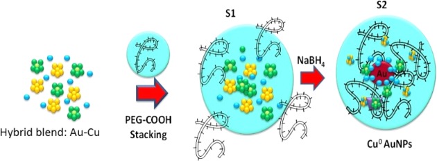
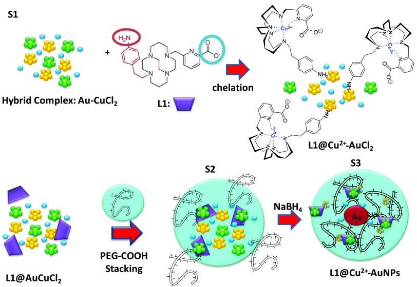
The formation of hybrid gold–copper NPs from Cu–Au mixture is summarized in Schemes 2 and 3. Step (1) was the complexation of solutions CuCl2–AuCl4– and generation of copper–gold clusters (see Scheme 2). Step (2) is the initial reduction of Au(III) ions by dicarboxylic acid-terminated poly(ethylene glycol) (PEG) that adsorbed onto Cu–Au clusters (Scheme 2); the last step (3) is the reduction of metal ions in that vicinity and the growth of hybrid gold particles (Cu0–AuNPs) together with the colloidal stabilization due to the molecules of PEG polymers.
Scheme 2. Schematic Representation of the Synthesis of Cu0–AuNPs via a Two-Step Process.
Please note that drawings are not in scale and are not intended to be representative of the full samples composition.
Scheme 3. Schematic Representation of the Synthesis of L1@Cu2+–AuNPs via a Three-Step Process.
Please note that drawings are not in scale and are not intended to be representative of the full samples composition.
In this frame, L1 ligands take part in the reaction, thanks to their amino group onto copper–gold clusters in which copper was kept in oxidation state Cu2+ and chelated with them (Scheme 3). The positive charge of the amino group onto L1 ligand in water solutions showed strong electrostatic interaction with negatively charged Cu2+–AuCl ions and formed a complex L1@Cu2+–AuCl that played a final role in the growth of NPs. A large excess of L1 ligand in the mixture was required to chelate completely all Cu2+. The addition of diacid PEG improved the kinetics of reduction by complexation of Cu–Au ions,28,26 just tuning the growth process of hybrid nanoparticles. During the S2 phase (Scheme 3), L1@Cu2+–AuCl complexes migrated through PEG molecules. Thus, an appreciable amount of complexes diffused and were captured inside the PEG layer via a mechanism similar to the other ligand complexes loaded onto nanostructures.16,24,29 Based on previously research studies,30 we suppose that when PEG was added to the L1@Cu2+–AuCl, the PEG initially was bound to hybrid complex in a mushroom conformation followed by a conformational change to brush mode.15,17 The final reduction by NaBH4 completed the grow process to form L1@Cu2+–AuNPs. All products of our synthetic procedure were characterized by UV–vis absorption spectroscopy, transmission electron microscopy (TEM), and Raman spectroscopy.
2.3. Comparative Physicochemical Characterization of Cu0–AuNPs and L1@Cu2+–AuNPs
TEM images of Cu0–AuNPs showed a well dispersion of the nanoparticles with an average size of 20 ± 1 nm (Figure 2A overpanel). Different nanostructures were obtained with L1@Cu2+–AuNPs: they exhibited a nanocapsule-like shape embedded in a shell of PEG, in which metal nanoparticles showed a diameter of around 28 ± 2 nm (Figure 2A underpanel). The synthesis of Au/Cu alloy nanoparticles using biocompatible liquid polymer22 and the fabrication of snowflakes nanoparticles by catalytic CO oxidation11 have been already reported. Anyway, a study about the grafting of L1 ligands onto Cu0–AuNPs has not been reported. When L1 ligands were added to the Cu2+–AuCl solution, the picolinate amino group was initially electrostatically bound to Au–Cu clusters, followed by a conformational change of the ligand L1 that chelated Cu2+ ions completely and successively embedded in the dicarboxylic PEG in a mushroom conformation.15
Figure 2.
(A, A′) TEM images of Cu0–AuNPs (panel A) and L1@Cu2+–AuNPs (panel A′). (B) Normalized UV–vis absorption and scale bars: 50 and 20 nm for Cu–AuNPs and 0.2 μm and 100 nm for L1@Cu2+–AuNPs and CuCl2·6H2O as control. (C) Raman spectra of Cu–AuNPs and L1@Cu2+–AuNPs products compared to free L1 and CuCl2·6H2O as control. Raman spectra. Experimental conditions: λexc = 785 nm; laser power 20 mW; accumulation time 180 s.
Figure 2B black line reports the absorption spectra of hybrid Cu0–AuNPs, all characterized by a surface plasmon band in the range of 560 nm, together with a small peak at 775 nm. The slow shift of the band position depended on the ratio of the gold salt and the capping materials during the reaction processes.31,32 This peak could be generally ascribed to collective oscillation, known as the surface plasmon oscillation of the metal electrons in the conduction band, due to interaction of electrons with light of a certain wavelength. PEG could be used as a stabilizing polymer for AuNPs because the dispersed solutions could be obtained due to the formation of coordination bands between Au and Cu ions with the carboxylic group. The chelation effect even better dispersed Au and Cu ions, which were reduced to form single Cu0–AuNPs of relatively uniform size. Figure 2B red line displays a UV–vis an absorption spectrum of L1@Cu2+–Au NPs. Compared with Cu0–AuNPs spectrum, a blue shift of the plasmon peak from 560 to 535 nm and a red shift of the peak at 775–810 nm could be observed. The latter was associated to π–π* electronic transitions due to interactions between the L1 ring and CuAuCl2 ions and gave a clear evidence of the complex formation with a change of color of the colloidal solution from pink red (Cu0–AuNPs) to bright violet (L1@Cu2+–Au NPs).
The NP sizes were confirmed by dynamic light scattering (DLS) measurements (Table 1). ζ-Potential measurements showed that Cu0–AuNPs and L1@Cu2+–AuNPs were stable colloids at physiological pH (ζ-potential = −25 ± 3 and −20 ± 2 mV with a PdI equal to 0.3) (Table 1). This stability was enhanced by the presence of the PEG layer around nanoparticles.26
Table 1. ζ-Potential and Hydrodynamic Diameter of Cu0–AuNPs and L1@Cu2+–AuNPs.
| synthetic product | ζ-potential (mV) | hydrodynamic diameter (nm) | PdI |
|---|---|---|---|
| Cu0–AuNPs | –25 ± 3 | 20 ± 2 | 0.3 |
| L1@Cu2+–AuNPs | –20 ± 2 | 28 ± 2 | 0.3 |
Raman spectra of Cu0–AuNPs exhibited many bands in the region 500–2000 cm–1 (Figure 3C black line). The wide band observed around 1600 cm–1 on the Raman spectra was assigned to the water. The strong band at 1712 cm–1 was assigned to C=O carbonyl stretching of PEG diacid. The intense doublet at 720–760 cm–1 was due to the C–H plane deformation and a strong peak at 1439 cm–1 was assigned to νC–C stretching. These bands were due to the variation of the steric conformation of the PEG diacide and became more prominent upon complexation with Cu–AuCl2, as previously described.16,20 As matter of fact, when C=O and hydroxyl groups of PEG diacide interacted with a metal, the sterical conformation became more tilted with respect to the planar one. Focusing on the spectral range 200–500 cm–1 (Figure 2C), we can observe several spectral changes, which confirmed a chemical modification of Cu after complexation with gold ions and PEG diacide molecules. One of the Raman fingerprint of the Cu–PEG–AuNPs was the presence of a band around 263 cm–1, and a double peak at 235–285 cm–1 was observed. These bands could be assigned to the gold chloride stretches, ν(Au–Cl), and δ(O–Au–O) and δ(Cu–Au–O) are a clear evidence of the formation of a complex between AuCl2– and Cu and PEG diacide in the solution. The peak at 430 cm–1 was due to the vibrations δ(OH···O), ν(OH···O) of the PEG, as previously described.15,16 The bands in the region 3000 cm–1 could be assigned to the aromatic C–H stretching (Figure 2C). A broad band composed of some peaks appeared in the spectral range 2850–2930 due to the symmetric CH2–CH3 stretch vibration of PEG diacide molecules, confirming the main role of the polymer in the synthesis of the nanoparticle. The steric arrangement of L1 ligand during the synthesis process of PEGylated copper–gold nanoparticles was confirmed by Raman spectroscopic analysis (Figure 2C).
Figure 3.
Cytotoxicity of ES cells incubated with different concentrations of Cu0–AuNPs or L1@Cu2–AuNPs nanoparticles (0–10 μM) for 24 h. Bar = 50 μm.
Raman spectra of free L1@Cu2+–AuNPs in water showed SERS effect in the range 300–1800 cm–1. The spectral modifications were evidence of the steric conformational change of the L1 after grafting on the copper–gold nanoparticles. One of the Raman fingerprints of the L1@Cu2+–AuNPs was the presence of a band around 340 cm–1 due to the copper(II) peroxide complex, where L1 chelates Cu2+. The common peak at 450 cm–1 was due to the vibrations δ(OH···O), ν(OH···O) of the PEG as previously described.15,16 On the basis of the spectrochemical and previously theoretical findings, we assumed that Au3+ ions promoted the deprotonation of the L1 amino group. These bands were due to variation of the steric conformation of the L1 and became more prominent upon electrostatic interaction with gold cluster and then chelation with Cu2+.
2.4. Cytotoxicity of Cu0–AuNPs and L1@Cu2+–AuNPs
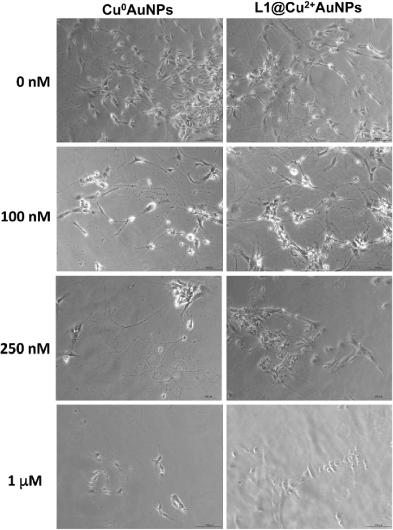
Murine ES cells and neural-derived ES cells were exposed to Cu0–AuNPs and L1@Cu2+–AuNPs nanoparticles at different concentrations (0–1000 nM) for 24 h (Figure 3), and cytotoxicity was analyzed by live–dead staining, and LC50 was calculated. At maximum used concentration (10 μM), both kinds of nanoparticles determined the death of almost all the cells. They resulted not cytotoxic for concentrations up to 100 nM, suggesting a fair good biocompatibility at this concentration. However, the NPs were found to display significant cytotoxicity still at the concentration of 250 nM. The nanoparticles showed concentration-dependent cytotoxicity in both cells: the neural-derived ES cells were more sensitive toward the toxicity of both particles than the undifferentiated ES cells. The results highlight the difference of cytotoxicity between nanoparticles used and differential sensitivity of cells to Cu0–AuNPs or L1@Cu2–AuNPs. However, the toxic response varied depending on the type of cell exposed due to differential sensitivity.
The results obtained on ES cells were used to identify the range of NPs concentrations to test the cytotoxicity on neural-derived ES cells. These cells were exposed to the same concentration of Cu0–AuNPs and L1@Cu2+–AuNPs, i.e., 0–100–250–1000 nM, for 24 h. The 50% of lethal dose for both NPs, reported in Table 2, was determined using trypan blue dye exclusion.
Table 2. LD50 of Neural-Derived ES Cells after 24 h of Treatment with Cu0–AuNPs or L1@Cu2+–AuNPs Nanoparticles.
| LD50% (nM) | LD50% (μg/mL) | |
|---|---|---|
| Cu0–AuNPs | 600 | 0.16 |
| L1@Cu2+–AuNPs | 950 | 0.25 |
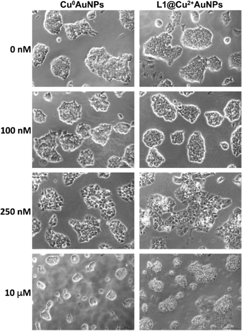
On neural-derived ES cells, the Cu0–AuNPs were more toxic, with LD50 value of 600 nM, than the L1@Cu2+–AuNPs nanoparticles, with LD50 value of 950 nM. Light microscopy analysis characterized the effect of different concentrations of NPs on neural-derived ES cells morphology. Even at 100 nM, both NPs preserved the cell viability and morphology, with quite equal toxicity profile observed for both NPs; at 250 nM, neural-derived ES cells treated with L1@Cu2+–Au NPs exhibited more neurite reduction than those treated with Cu0–AuNPs. At 1000 nM of both NPs, the cells appeared to refract the light, suggesting a typical apoptotic phenotype (Figure 4).
Figure 4.
Cytotoxicity of neural-derived ES cells incubated with different concentrations of Cu0–AuNPs or L1@Cu2+–AuNPs nanoparticles (0–100–250–1000 nM) for 24 h. Bar = 50 μm.
2.5. Determination of Cellular Uptake of NPs by Confocal Microscopy
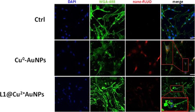
The neural-derived ES cells were plated on a gelatin-coated microscope slide and left to adhere overnight before adding Cu0–AuNPs and L1@Cu2+–AuNPs labeled with the fluorophore at 200 nM, a concentration well below the LD50 for both kinds of NPs. As shown in Figure 5, both NPs synthetized were internalized into neural-derived ES cells but with some qualitative differences. Confocal images showed Cu0–AuNPs internalized more than L1@Cu2+–AuNPs. Moreover, even if slightly larger, the Cu0–AuNPs were internalized also inside the nucleus. This capability may be caused by a more efficient interaction with mammalian cell membranes.
Figure 5.
Confocal fluorescence images of neural-derived ES cells incubated with Cu0–AuNPs or L1@Cu2+–AuNPs (200 μg/mL) for 24 h. Bar = 50 μm.
Confocal images confirmed that NPs were mainly located within the cell and not adhered to the cell surface: the fluorescent signal of Cu0–AuNPs was predominantly observed in the cytoplasm and also in the nuclei; on the contrary, the fluorescent signal of L1@Cu2+–AuNPs was prevalently present in the cytoplasm (Figure 5).
From data collected in biological experiments, a type-selective difference in NP toxicity was observed. A possible reason for the difference in uptake and distribution inside the neural-derived ES cells could be the different surface chemistry of two NPs synthetized, which could improve the endocytosis mechanisms up to the nucleus in case of Cu0–AuNPs. Experimental results indicated that the differences between Cu0–AuNPs and L1@Cu2+–AuNPs nanoparticles as well as the target cell type were critical determinants of intracellular responses and degree of cytotoxicity. At this stage, it was not possible to completely highlight the mechanism underlying the differential toxicity. The evidence emerging from the experimental results was that apoptosis is the predominant death pathway for moderate concentrations of NPs in the solution, whereas necrosis was the predominant pathway for high concentrations of NPs, according to the data reported in literature.33,34 Large amount of Cu-based nanoparticles, once internalized in neurons, caused severe alterations of cell morphology up to membrane disruption, according to the images reported in Figure 4 from concentrations of 100 nM onward. Light concentration of copper NPs inside neuron cells caused apoptosis as a consequence of oxidative stress induced by reactive oxygen species associated to metallic nanoparticles.
2.6. Optical Imaging of Cells
Internalization of cells of the synthesized colloids (Cu0AuNPs and L1@Cu2+AuNPs) was carried out with a confocal microscope (Horiba Scientifics) under bright- and dark-field illumination. The images reported in Figures S3 and S4 are from the treated ES neuronal cells in different areas, the same sample region was seen in bright-field (a) and dark-field conditions (b). The dark-field image showed a high density of bright, small scattering centers dispersed all over the glass slide. The density of these bright spots clearly showed an effect of concentration addiction when the colloids were incubated. It appears that the colloids had a tendency to accumulate inside the cells in the experimental conditions previously described.17
3. Materials and Methods
All chemicals were of reagent grade or higher and used as received unless otherwise specified. Tetrachloroauric acid (HAuCl4·H2O), CuCl2·6H2O, sodium borohydride (NaBH4), poly(ethylene glycol)-600 (PEG 600), and phosphate buffered saline (PBS, 0.1 M, pH 7.0, pH 4.0, pH 9.0) were purchased from Organics and from Aldrich Chemical Co.
3.1. L1 Synthesis
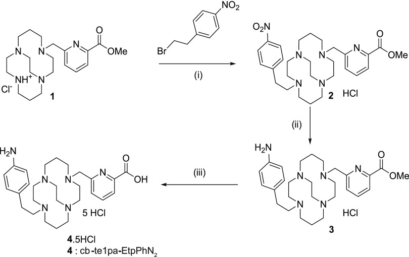
L1 synthesis was based on previous work that is summarized in Scheme 4. Briefly, starting from compound 1, the methyl ester of te1pa, the addition of 4-nitrophenylethyl bromide led to compound 2 with 85% yield. The specific reduction of the nitrophenyl was managed with tin chloride with 83% yield and produced compound 3. A final hydrolysis removed the ester function and generated the bifunctional cb-te1pa-EtpPhNH2 (compound 4). In the following sections, the final product cb-te1pa-EtpPhNH2 will be simply called L1.
Scheme 4. Synthesis of L1 (cb-te1pa-EtpPhNH2): L1.
(i) K2CO3, CH3CN, 12 h, reflux, 85%; (ii) tin chloride MeOH/HCl aq 12 M, room temperature, 12 h, 83%; and (iii) hydrochloric acid 6 M, reflux, 12 h, quant.
NMR was performed on Bruker 300 advance spectrometers. 2D NMR 1H–1H homonuclear, 1H–13C heteronuclear correlations, and homonuclear decoupling experiments were used for assignment of the 1H and 13C signals. The δ scales are relative to tetramethylsilane (1H, 13C). The signals are indicated as follows: chemical shift, intensity, multiplicity (s, singlet; br s, broad singlet; d, doublet; t, triplet; m, multiplet; q, quartet), coupling constants J in hertz (Hz). The high resolution mass spectrometry (HR-MS) analyses were performed at the Institute of Analytic and Organic Chemistry, ICOA in Orleans. In details, compound L1 was synthetized by a three-step procedure, which is reported in the following section. Results of HR-MS are reported for each step in the Supporting Information.
3.1.1. Step (i): trans-Di-N-functionalization of Cross-Bridged Monomethylpicolinate Cyclam (Compound 1) Yielding Compound 2
4-Nitrophenylethyl bromide (0.968 g, 4.20 mmol) and potassium carbonate (0.872 g, 6.31 mmol) were add to a solution of 1 (0.865, 2.10 mmol) in 200 mL of distilled acetonitrile. The mixture was refluxed overnight. After the evaporation of the solvent, the crude product was purified by column chromatography in silica gel (CHCl3/MeOH 8:2) to yield compound 2 as a yellow oil (1.000 g, 85%).
3.1.2. Step (ii): Reduction of Compound 2 Yielding Compound 3
Tin chloride (1.810 g, 9.55 mmol) and compound 2 (0.500 g, 0.95 mmol) were add to a 40 mL solution 1:9 of MeOH/HCl aq 12 M. The mixture was stirred at room temperature overnight and then excess HCl was neutralized using potassium carbonate. The desired compound 3 was obtained by extraction with chloroform at pH 14 as yellow oil (420 mg, 83%).
3.1.3. Step (iii): Hydrolysis of Compound 3 Yielding Compound 4 (L1)
Hydrochloric acid (10 mL, 6 M) was slowly added to compound 3 (0.200 g, 0.38 mmol) and the mixture was refluxed overnight. After cooling to room temperature, the solvent was evaporated to yield compound 4 (L1) as an off-white solid in quantitative yield.
3.2. Synthesis of Cu0–AuNPs
Twenty milliliters of 0.0001 M aqueous HAuCl4 was mixed with 5 mL of CuCl2·6H20 solution (6.10 × 10⁻⁵ M in water) at room temperature for 1 h under magnetic stirring to form a Au–Cu blend. Then, 250 μL of poly(ethylene glycol) 600 diacid (PEG) was mixed to the blend solution under stirring for 2 h. After this time, 3.6 mL of NaBH4 (0.01 M) was added dropwise, followed by rapid stirring and kept without agitation for 2 h. The color of the dispersion indeed instantly changed from green-yellow to pink-red when sodium borohydride was added to a solution of copper–gold precursor in the presence of the PEG diacid polymer, with a complete reduction of metal ions confirming the formation of hybrid nanoparticles in the solution. The as-prepared Cu0–AuNPs solution was purified by centrifugation and dialysis to remove excess of not-conjugated dicarboxylic PEG.14
3.3. Synthesis of L1@Cu2+–AuNPs
The synthesis of L1@Cu2+–AuNPs colloids is described here. Twenty milliliters of HAuCl4 aqueous solution (2.5 × 10⁻⁴ M in water) was added to CuCl2 solution (5 mL, 6.10 × 10⁻⁵ M in water) under stirring for 1 h. After this time, 5 mL of L1 (2.3 × 10⁻⁴ M in water) was mixed to this hybrid blend solution during 1 h, and the mixture was stirred at room temperature. At the end of this reaction, 250 μL of dicarboxylic PEG was mixed to the solution and stirred for 1 h. Finally, 3.6 mL of aqueous 0.01 M NaBH4 was added at once until stabilization and reduction to hybrid nanoparticles. The “as-prepared” L1@Cu2+–AuNPs solution was centrifuged at 5000 rpm for 20 min for three times and then the supernatant was discarded. This was repeated twice to remove excess of not-conjugated reagents. L1@Cu2+–AuNPs were stored at 8 °C and characterized by UV–vis spectroscopy, transmission electron microscopy, and Raman spectroscopy.
3.4. Physicochemical Characterization
All the measurements were performed in triplicate to validate the reproducibility of the synthetic and analytical procedures.15,16
3.4.1. UV–Vis Measurements
Absorption spectra were recorded using a PerkinElmer Lambda UV/Vis 950 spectrophotometer in plastic cuvettes with an optical path of 10 mm. The wavelength range was 200–900 nm.
3.4.2. Transmission Electron Microscopy (TEM)
Size and morphology of NPs were characterized by transmission electron microscopy (TEM) (JEM-1011 TEM, Jeol, Inc., Peabody, MA) using a Morada CCD camera at an accelerating voltage of 100 kV.
3.4.3. Raman Spectroscopy
The Raman experiments have been performed on an Xplora spectrometer (Horiba Scientifics-France).15,16
3.4.5. Optical Imaging
The optical images of the cells were carried out as previously reported.17
3.4.6. Dynamic Light Scattering (DLS)
The size measurements were performed using a Zetasizer Nano ZS (Malvern Instruments, Malvern, U.K.) equipped with a He–Ne laser (633 nm, fixed scattering angle of 173°) at room temperature.
3.4.7. ζ-Potential Measurements
The ζ-potential of AuNPs dispersed in water was measured using the electrophoretic mode of a Zetasizer Nano ZS (Malvern Instruments Ltd, U.K.).
3.5. ES Cells Culture Conditions
Embryonic stem cells (ESCs) can be used as a model system in basic research, drug discovery, biomedical applications, and nanotechnology because they combine the potential of unlimited self-renewal with the ability to differentiate into a wide range of tissue-specific cells. The present study was designed to determine if the nanoparticles Cu0–AuNPs and L1@Cu2+–AuNPs could have toxic effects on undifferentiated and neural differentiated ES cells. Wild-type mouse AK7 ES cells were maintained in an undifferentiated state by culture on a monolayer of mitomycin-C-inactivated fibroblast in the presence of leukemia-inhibiting factor as previously described.18 At 24 h before treatment, the cells were seeded on gelatin-coated plates at a density of 4 × 10⁴ cells/cm2 to allow attachment.
3.5.1. In Vitro Neurons Differentiation
Neural progenies can be generated from ESC with high standards of accuracy and reliability. To induce neural differentiation, essentially according to Fico et al.,18 AK7 ES cells at 48 h before inducing differentiation were seeded on gelatin-coated plates. At day 0, the ES cells were dissociated in a single-cell suspension and 1500 cells/cm2 were plated on gelatin-coated plates. The cells were maintained in differentiation medium until day 7 when neural precursors cells were detached using 0.05% trypsin/ethylenediaminetetraacetic acid solution and frozen in 90% FBS + 10% dimethyl sulfoxide. Frozen cells were thawed and immediately plated at 66 000 cells/cm2 in Matrigel-coated plates. The medium was changed every day until day 13.
3.6. Cell Death Assay
The lethal dose 50 (LD50) is the amount of a chemical, calculated as the concentration of chemicals that produces death in 50% of a cellular population.
To determine the lethal dose 50 (LD50) of the nanoparticles Cu0–AuNPs and L1@Cu2+–AuNPs on undifferentiated ES and neural-derived ES cells, these cells were seeded, respectively, on gelatin-coated or Matrigel-coated plates. The cells were untreated or treated with different concentrations (0–1000 nM) of Cu0–AuNPs or L1@Cu2+–AuNPs nanoparticles for 24 h, then collected, counted, and analyzed for their ability to incorporate the cell-permeable dye trypan blue. Concomitantly, other cells, untreated or treated in the same way, were visualized by phase-contrast microscopy using the DMI6000B inverted fully automated microscope with DFC 420 RGB camera (Leica Microsystems, Wetzelar, Germany). Leica LAS V5.4 software was used for image acquisition/elaboration (contrast/γ adjusting).
3.7. Immunofluorescence Analysis
For nanoparticles internalization experiments, neural-differentiated ESCs were seeded in six-well plates and cultured for 24 h. Cu0–AuNPs or L1@Cu2+–AuNPs conjugated with Alexa-Fluor-594, suspended in culture medium at 200 nM, were incubated with cells for 24 h. After the incubation, the cells were rinsed twice in PBS to remove the noninternalized nanoparticles, fixed in 4% paraformaldehyde for 30 min, and washed in PBS 1×. After washing, the cells were incubated with WGA-488 (Invitrogen) as membrane marker following manufacturer’s instructions. Nuclei were counterstained with Hoechst 33342 (Invitrogen). Fluorescent labeling was visualized using the inverted fully automated confocal Nikon AR-1 microscope. The NIS elements software was used for image acquisition/elaboration.
4. Conclusions
Designing hybrid functional nanoparticles for biomedical applications is still a current challenge in terms of performances, stability, and safety in biological media. In particular, if gold nanoparticles are known for their high in vivo inertness and their use in several applications, including their photophysical properties, the use of copper(II) into the hybrid nanoparticles is still not a trivial task. Once copper is inside the metallic aggregates, it is usual to obtain unstable and/or cytotoxic effects coming from the hybrid nanostructure.
The success of this study was then to provide the design, the synthesis, and the characterization of new potential nanocomplexes based on the incorporation of chelated copper(II) in gold nanoparticles. Highly thermodynamically stable and kinetically and electrochemically inert copper(II) chelates have been used based on a proven cyclam cross-bridged ligand, the cb-te1pa chelator. Its insertion was facilitated by the presence of aniline moiety, a carboxylic function, and its overall charge and proved all along the nanomaterials characterization. In conclusion, from the results obtained, there is evidence of a type-selective difference in NP toxicity in favor of L1@Cu2–AuNPs. Possible reason to explain nanoparticle-specific uptake and distribution inside the neural-derived ES cells may be attributed to the peculiar features of Cu0–AuNPs or L1@Cu2–AuNPs nanoparticles. Our results indicated that the differences between Cu0–AuNPs or L1@Cu2–AuNPs nanoparticles as well as the target cell type are critical determinants of intracellular responses and degree of cytotoxicity. These results allow us to hypothesize that the apoptosis is the predominant death pathway for moderate concentrations of NPs in the solution, whereas necrosis is the predominant pathway for high concentrations of NPs.
Toxicity comparison with respect to previously reported results in literature is not straightforward because ES neuron cells are not very commonly diffused in many laboratories; nevertheless, the synthetized Cu-based NPs showed LD levels of the same order of those mentioned in critical review study, recently published.35
Acknowledgments
With the support of SATT IDF Innov, J.S. has filed a patent application on the nanoparticles presented in this manuscript (Cu0–AuNPs). Nanomaterial and method of production of a nanomaterial for medical applications, such as MRI or SERS–Inventor: J.S., European Patent Application number EP17305087.3, filed January 27, 2017, and PCT application PCT/EP2018/051988 filed January, 26, 2018. This work has been partly performed on the CNano Mat platform of the University Paris 13. This work was partially funded by Italian Ministry of Health “Ricerca Corrente”, PONPE_00060_7 and PONPE_00060_3 to S.F. The authors acknowledge the Integrated Microscopy Facility at Institute of Genetics and Biophysics “Adriano Buzzati Traverso”, CNR in Naples for optical and confocal microscopy.
Supporting Information Available
The Supporting Information is available free of charge on the ACS Publications website at DOI: 10.1021/acsomega.8b03266.
UV–vis absorption of HAuCl4·6H2O (black line), CuCl2·6H2O (red line); and Au–Cu blend (blue line) (Figure S1); UV–vis spectra of each solutions: HAuCl4, CuCl2, and HAuCl4–CuCl2 (Figure S2); bright field (a) and dark field (b) images (100×, 0.9 NA objective) of neural derived-ES cells incubated with Cu0–AuNPs or L1@Cu2+–AuNPs (250 nM) (Figure S3); bright field (a) and dark field (b) images (100×, 0.9 NA objective) of neural derived-ES cells incubated with Cu0–AuNPs or L1@Cu2+–AuNPs (750 nM) (Figure S4) (PDF)
Author Contributions
The manuscript was written through contributions of all authors. All authors have given approval to the final version of the manuscript.
The authors declare no competing financial interest.
Supplementary Material
References
- Miller M. R.; Raftis J. B.; Langrish J. P.; McLean S. G.; Samutrtai P.; Connell S. P.; Wilson S.; Vesey A. T.; Fokkens P. H. B.; Boere A. J. F.; Krystek P.; Campbell C. J.; Hadoke P. W. F.; Donaldson K.; Cassee F. R.; Newby D. E.; Duffin R.; Mills N. L. ACS Nano 2017, 11, 4542–4552. 10.1021/acsnano.6b08551. [DOI] [PMC free article] [PubMed] [Google Scholar]
- Boonruamkaew P.; Chonpathompikunlert P.; Vong L. B.; Sakaue S.; Tomidokoro Y.; Ishii K.; Tamaoka A.; Nagasaki Y. Sci. Rep. 2017, 7, 3785 10.1038/s41598-017-03411-7. [DOI] [PMC free article] [PubMed] [Google Scholar]
- Chatterjee A. K.; Chakraborty R.; Basu T. Nanotechnology 2014, 25, 135101 10.1088/0957-4484/25/13/135101. [DOI] [PubMed] [Google Scholar]
- Henkel A.; Jakab A.; Brunklaus G.; Sönnichsen C. J. Phys. Chem. C 2009, 113, 2200–2204. 10.1021/jp810433e. [DOI] [Google Scholar]
- Shokeen M.; Anderson C. J. Acc. Chem. Res. 2009, 42, 832–841. 10.1021/ar800255q. [DOI] [PMC free article] [PubMed] [Google Scholar]
- Rout L.; Kumar A.; Dhaka R. S.; Reddy G. N.; Giri S.; Dash P. Appl. Catal., A 2017, 538, 107–122. 10.1016/j.apcata.2017.03.017. [DOI] [Google Scholar]
- Cai Z.; Anderson C. J. J. Labelled Compd. Radiopharm. 2014, 57, 224–230. 10.1002/jlcr.3165. [DOI] [PMC free article] [PubMed] [Google Scholar]
- Lu H. D.; Wang L. Z.; Wilson B. K.; McManus S. A.; Jumai’an J.; Padakanti P. K.; Alavi A.; Mach R. H.; Prud’homme R. K. ACS Appl. Mater. Interfaces 2018, 10, 3191–3199. 10.1021/acsami.7b07242. [DOI] [PubMed] [Google Scholar]
- Mewis R. E.; Archibald S. J. Coord. Chem. Rev. 2010, 254, 1686–1712. 10.1016/j.ccr.2010.02.025. [DOI] [Google Scholar]
- Odendaal A. Y.; Fiamengo A. L.; Ferdani R.; Wadas T. J.; Hill D. C.; Peng Y.; Heroux K. J.; Golen J. A.; Rheingold A. L.; Anderson C. J.; Weisman G. R.; Wong E. H. Inorg. Chem. 2011, 50, 3078–3086. 10.1021/ic200014w. [DOI] [PMC free article] [PubMed] [Google Scholar]
- Wong E. H.; Weisman G. R.; Hill D. C.; Reed D. P.; Rogers M. E.; Condon J. S.; Fagan M. A.; Calabrese J. C.; Lam K.-C.; Guzei I. A.; Rheingold A. L. J. Am. Chem. Soc. 2000, 122, 10561–10572. 10.1021/ja001295j. [DOI] [Google Scholar]
- Weisman G. R.; Rogers M. E.; Wong E. H.; Jasinski J. P.; Paight E. S. J. Am. Chem. Soc. 1990, 112, 8604–8605. 10.1021/ja00179a067. [DOI] [Google Scholar]
- Lima L. M.; Halime Z.; Marion R.; Camus N.; Delgado R.; Platas-Iglesias C.; Tripier R. Inorg. Chem. 2014, 53, 5269–5279. 10.1021/ic500491c. [DOI] [PubMed] [Google Scholar]
- You J.; Zhang G.; Li C. ACS Nano 2010, 4, 1033–1041. 10.1021/nn901181c. [DOI] [PMC free article] [PubMed] [Google Scholar]
- Spadavecchia J.; Movia D.; Moore C.; Maguire C. M.; Moustaoui H.; Casale S.; Volkov Y.; Prina-Mello A. Int. J. Nanomed. 2016, 11, 791–822. 10.2147/IJN.S97476. [DOI] [PMC free article] [PubMed] [Google Scholar]
- Moustaoui H.; Movia D.; Dupont N.; Bouchemal N.; Casale S.; Djaker N.; Savarin P.; Prina-Mello A.; de la Chapelle M. L.; Spadavecchia J. ACS Appl. Mater. Interfaces 2016, 8, 19946–19957. 10.1021/acsami.6b07250. [DOI] [PubMed] [Google Scholar]
- Monteil M.; Moustaoui H.; Picardi G.; Aouidat F.; Djaker N.; de La Chapelle M. L.; Lecouvey M.; Spadavecchia J. J. Colloid Interface Sci. 2018, 513, 205–213. 10.1016/j.jcis.2017.10.055. [DOI] [PubMed] [Google Scholar]
- Fico A.; Paglialunga F.; Cigliano L.; Abrescia P.; Verde P.; Martini G.; Iaccarino I.; Filosa S. Cell Death Differ. 2004, 11, 823–831. 10.1038/sj.cdd.4401420. [DOI] [PubMed] [Google Scholar]
- Ly N. H.; Nguyen T. D.; Zoh K. D.; Joo S. W. Sensors 2017, 17, 2628 10.3390/s17112628. [DOI] [PMC free article] [PubMed] [Google Scholar]
- Emmenegger F. P.; Rohrbasser C.; Schläpfer C. W. Inorg. Nucl. Chem. Lett. 1976, 12, 127–131. 10.1016/0020-1650(76)80186-9. [DOI] [Google Scholar]
- Pal U.; Sanchez Ramirez J. F.; Liu H. B.; Medina A.; Ascencio J. A. Appl. Phys. A 2004, 79, 79–84. 10.1007/s00339-003-2478-9. [DOI] [Google Scholar]
- Nguyen M. T.; Zhang H.; Deng L.; Tokunaga T.; Yonezawa T. Langmuir 2017, 33, 12389–12397. 10.1021/acs.langmuir.7b03194. [DOI] [PubMed] [Google Scholar]
- Marguerit G.; Moustaoui H.; Haddada M. B.; Djaker N.; de la Chapelle M. L.; Spadavecchia J. Part. Part. Syst. Charact. 2018, 35, 1700299 10.1002/ppsc.201700299. [DOI] [Google Scholar]
- Politi J.; De Stefano L.; Longobardi S.; Giardina P.; Rea I.; Methivier C.; Pradier C. M.; Casale S.; Spadavecchia J. Colloids Surf., B 2015, 136, 214–221. 10.1016/j.colsurfb.2015.09.021. [DOI] [PubMed] [Google Scholar]
- Spadavecchia J.; Apchain E.; Alberic M.; Fontan E.; Reiche I. Angew. Chem., Int. Ed. 2014, 53, 8363–8366. 10.1002/anie.201403567. [DOI] [PubMed] [Google Scholar]
- Lu H. D.; Wang L. Z.; Wilson B. K.; McManus S. A.; Jumai’an J.; Padakanti P. K.; Alavi A.; Mach R. H.; Prud’homme R. K. ACS Appl. Mater. Interfaces 2018, 10, 3191–3199. 10.1021/acsami.7b07242. [DOI] [PubMed] [Google Scholar]
- Gammage M. D.; Stauffer S.; Henkelman G.; Becker M. F.; Keto J. W.; Kovar D. Surf. Sci. 2016, 653, 66–70. 10.1016/j.susc.2016.05.008. [DOI] [Google Scholar]
- Gautier J.; Allard-Vannier E.; Munnier E.; Souce M.; Chourpa I. J. Controlled Release 2013, 169, 48–61. 10.1016/j.jconrel.2013.03.018. [DOI] [PubMed] [Google Scholar]
- Lee K. Y. J.; Wang Y.; Nie S. RSC Adv. 2015, 5, 65651–65659. 10.1039/C5RA09872F. [DOI] [Google Scholar]
- Sajanlal P. R.; Sreeprasad T. S.; Samal A. K.; Pradeep T. Nano Rev. 2011, 2, 5883 10.3402/nano.v2i0.5883. [DOI] [PMC free article] [PubMed] [Google Scholar]
- Toma H. E.; Zamarion V. M.; Toma S. H.; Araki K. J. Braz. Chem. Soc. 2010, 21, 1158–1176. 10.1590/S0103-50532010000700003. [DOI] [Google Scholar]
- Prabhu B. M.; Ali S. F.; Murdock R. C.; Hussain S. M.; Srivatsan M. Nanotoxicology 2010, 4, 150–160. 10.3109/17435390903337693. [DOI] [PMC free article] [PubMed] [Google Scholar]
- Liu Z.; Shichang L.; Guogang R.; Taoc Z.; Zhuo Y. J. Appl. Toxicol. 2011, 31, 439–445. 10.1002/jat.1611. [DOI] [PubMed] [Google Scholar]
- Bondarenko O.; Juganson K.; Ivask A.; Kasemets K.; Mortimer M.; Kahru A. Arch. Toxicol. 2013, 87, 1181–1200. 10.1007/s00204-013-1079-4. [DOI] [PMC free article] [PubMed] [Google Scholar]
Associated Data
This section collects any data citations, data availability statements, or supplementary materials included in this article.


