Abstract
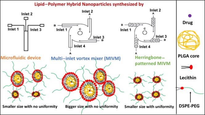
Major barriers to the implementation of nanotechnology include reproducible synthesis and scalability. Batch solution phase methods do not appear to have the potential to overcome these barriers. Microfluidic methods have been investigated as a means to enable controllable and reproducible synthesis; however, the most popular constituent of microfluidics, polydimethylsiloxane, is ill-suited for mass production. Multi-inlet vortex mixers (MIVMs) have been proposed as a method for scalable nanoparticle production; however, the control and reproducibility of the nanoparticle is wanting. Here, we investigate the ability to improve the control and reproducibility of nanoparticles produced by using 3D printed MIVMs with herringbone patterns in the flow channels. We compare three methods, viz., microfluidic, MIVM, and herringbone-patterned MIVM methods, for the synthesis of lipid–polymer hybrid nanoparticles (LPHNPs). The 3D printed herringbone-patterned MIVM method resulted in the smallest LPHNPs with the most uniform size distribution and shows more reproducible results as compared to the other two methods. To elucidate the mechanism underlying these results, concentration slices and vorticity streamlines of mixing chambers have been analyzed for 3D printed herringbone-patterned MIVM devices. The results bode well for LPHNPs, a formulation widely investigated for its improved therapeutic efficacy and biocompatibility. The herringbone-patterned device also has the potential to be broadly applied to many solution phase processes that take advantage of efficient mixing. The methods discussed here have broad implications for reproducible production of nanoparticles with constituents such as siRNA, proteins, quantum dots, and inorganic materials.
Introduction
Significant nanotechnology contributions have been made to a myriad of fields including information technology, medicine, energy, food safety, and environmental science.1−5 In medicine, nanoparticles are poised to revolutionize the established field of drug-delivery.6 A common technique involves engineering nanoparticles to target and deliver drugs to diseased cells. Targeted nanoparticle delivery is poised to significantly reduce drug effects on healthy cells in the body and thereby reduce the negative side-effects of the drug.7 Lipid–polymer hybrid nanoparticles (LPHNPs) consisting of a hydrophobic polymer core and a lipid polymer shell represent a new and promising nanoparticle drug-delivery platform because they provide options for surface functionality, high drug loading yields, sustained drug release profile, and excellent in vitro and in vivo stability.8−13
Conventional methods of synthesizing LPHNPs are time-consuming and thus leave significant room for improvement. Some of these conventional methods include emulsion formation, sonication, and solvent evaporation.14 The repeatability and reproducibility of these methods is a translational concern as the synthesized nanoparticles may show poor size distribution and low efficacy because of the lack of fluidic control offered by these methods.15 Recent techniques such as microfluidics and multi-inlet vortex mixers (MIVMs) enable rapid mixing and flash precipitation with precise control of fluids yielding size- and structure-controlled LPHNPs.16,17 In addition to this, these methods are simple as well as cost-effective as compared to other reported methods. With the advent of 3D printing, significant control of fluidic parameters can be extended beyond channel dimensions and basic geometry. It can include easily incorporated patterns that can be used to alter fluid dynamics.
Polydimethylsiloxane (PDMS) is a common component for microfluidic device fabrication because it is a cost-effective material; however, PDMS is not well-suited for mass production because of the substantial human labor and the layered molding that limits the 3D complexity of the devices that can be produced.18 Silicon substrates and glass have been proposed as alternatives but require sophisticated fabrication processes that are cost- and access-prohibitive. Despite the traction gained by the 3D printing of microfluidics, printing resolution, throughput, and resin biocompatibility are common issues. MIVMs have been demonstrated for scalable production; however, they have the drawbacks of traditional bulk synthesis methods. Toward the end of combining the advantages of microfluidics and MIVM systems, we have explored herringbone-patterned 3D printed reactors.
Rifampicin-loaded LPHNPs (RLPHNPs) have been synthesized by the three different fluidic methods: microfluidics, MIVM, and a 3D printed MIVM with herringbone patterns. Rifampicin was chosen as the drug as it has considerable potential for treatment of tuberculosis.19 Antibiotics for TB have many adverse side-effects such as loss of appetite, nausea, and dizziness because of which many of the patients discontinue the treatment, which ultimately results in spreading of the disease. Hence, rifampicin-loaded nanoparticles are of interest for increased patient adherence to tuberculosis drug regimens. Primarily, effects of various parameters such as flow-rates and encapsulation efficiency on the RLPHNP synthesis have been evaluated systematically. On the basis of the obtained results, synthesis conditions have been optimized to obtain RLPHNPs with desired shape, that is, spherical, and size, ∼100 nm.
Further, the synthesis of Myristic acid-loaded LPHNPs has also been carried out by microfluidics, MIVM, and 3D printed MIVM with herringbone pattern. Myristic acid has been chosen because it may be an effective drug for cardiovascular diseases.20 The synthesis has been repeated five times keeping all the synthesis and production parameters constant and comparison has been made among these three methods on the basis of size and polydispersity of LPHNPs. Nanoparticle composition and fabrications techniques used in this study help to narrow down the formulation and methods for the production of LPHNPs for possible preclinical and drug delivery applications in the future.
Device Fabrication
Microfluidic Device Fabrication
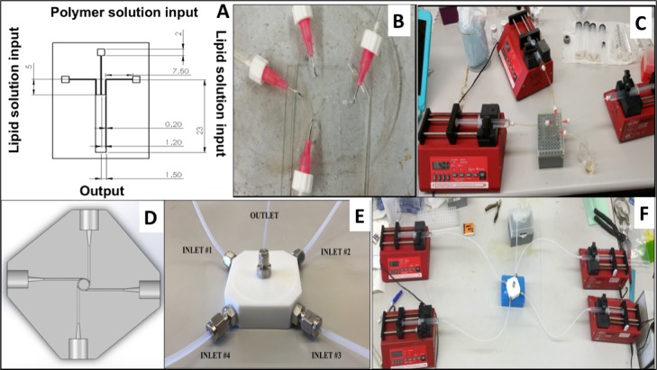
The microfluidic device design was prepared by using AutoCAD with the appropriate dimensions as shown in Figure 1A. A silicon wafer was coated with an SU-8 coating (protective coating) in the shape of the microfluidic device and further used for fabrication. Sylgard 184 Silicone Elastomer was used to create a mold for the microfluidic device. To prepare the elastomeric mold of PDMS, silicone elastomer base (Sylgard 184) and curing agent were mixed (10:1 ratio by weight) and placed in a vacuum chamber to remove excess air bubbles. The PDMS was poured onto the mold wafer and cured on a hot plate of 150 °C for 10 min. The PDMS mold was then peeled off from the wafer. The microfluidic device was cut out from the PDMS mold with a razor blade, punched with holes for the inlets and outlets, and bonded onto a glass slide with plasma treatment. Plasma treatment was applied at a medium level for 30 s. The fabricated microfluidic device and the experimental setup for the microfluidic device is shown in Figure 1B,C, respectively.
Figure 1.
(A) Schematic of the microfluidic device (units are in millimeters); (B) fabricated microfluidic device; (C) experimental setup for the microfluidic device; (D) schematic for the MIVM design; (E) fabricated MIVM device; and (F) experimental setup for the MIVM device.
MIVM Device Fabrication
A modeling program called SolidWorks was utilized to design the MIVM device. The design was based on the design created by Liu et al. and the dimensions were approximate to the values indicated in various literature papers.21,22 The external and internal geometry of the device is shown in Figure 1D,E, including four holes where the inlet fittings were tapped, the inlet channels that lead from the inlets to the mixing chamber; the mixing chamber where the reactants mix; and the hole where the outlet fitting was tapped. After the three-dimensional model was complete, the SolidWorks file was used by a Computer Numerical Control (CNC) machinist to create the Teflon prototype. Figure 1F shows the experimental setup for the MIVM device.
3D Printed MIVM with Herringbone Pattern Fabrication
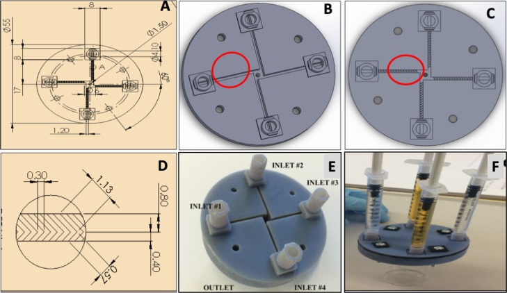
In a 3D printed MIVM device, a herringbone pattern was incorporated into the bottom surface of the inlet channels. The pictorial representation of MIVM without and with the herringbone pattern is shown in Figure 2A–C. The herringbone pattern consisted of repeated patterns of grooves on the bottom of the microchannel. The individual groove was composed of channels of two different lengths connected to each other, one relatively longer and the other relatively shorter, and those two grooves meet with a certain angle. The herringbone pattern follows the direction of the flow and spans the full width of the inlet channel with the arms of the chevrons offset in length by a 2:1 ratio as shown in Figure 2D. The herringbone geometries are loosely based on designs by Manda and are scaled up from the micrometer scale, which are also given in Figure 2D.23 The 3D printed MIVM devices were made in four different variations with three devices having different distances between the herringbone grooves (600, 750, and 900 μm) and one without a herringbone pattern as the control (Figure 2B). On the basis of the study conducted by Chan et al., a mixing chamber size of 4 mm was determined as the most optimum size for mixing efficiency.24 The isometric view of the MIVM device used for incorporating the herringbone pattern is shown in Figure 2E. Once device modeling was completed, a 3D printer was used to physically create the device. The experimental setup used for the MIVM device with the herringbone pattern is shown in Figure 2F.
Figure 2.
(A) Schematic of the MIVM design (B) without and (C) with the herringbone pattern; (D) schematic representation of the herringbone pattern (all the units are in millimeters); (E) isometric view of the fabricated MIVM device; and (F) experimental setup for the herringbone pattern.
Results and Discussion
Synthesis of RLPHNPs by the Microfluidic Method
One of the newly applied methods for fabricating core–shell-type hybrid NPs is the microfluidic method. In the microfluidic device, a polymer with the drug solution was introduced from the middle inlet and the lipid solution was introduced from the two side inlets. At the outlet chamber, the lipid shell was adsorbed onto the surface of the poly(lactic-co-glycolic acid) (PLGA) core through hydrophobic interaction between the aliphatic chain of the lipid and PLGA, to form the lipid–PLGA core–shell NP.25 Initially, to optimize the production parameters, synthesis of LPHNPs was attempted with variable drug-loading amounts and flow rates.
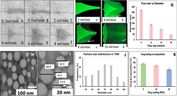
The effects of different flow rates through the microfluidic device were observed and recorded under a light microscope using dyed water. Figure 3A–F shows the effect of different flow rates applied to the side channels, whereas the flow rate of the middle channel was kept constant at 0.1 mL/min. As can be noted from Figure 3A–C, as the flow rate of the side channels increased, the water flow of the middle channel becomes narrow. This may be due to increased pressure from the outside flow, which pushes the flow into the mixing channel. However, when the flow rate of the outside channel was increased to 20 times that of the middle channel (more than 2 mL/min), the flow from the middle channel began to spread outwards toward the edges to compensate for the low pressure created at the inlet of the side channel by the high flow rate. This can be clearly observed from Figure 3D–F. At a flow rate of 4, 6, and 8 mL/min, microvortices began to form, which is indicated by the large spread of the dyed water across the channel in a parabolic manner. This pattern was maintained as long as the flow rate ratio was steady, indicating that the flow was not random but a controlled turbulence.
Figure 3.
(A–F) Flow images of the middle channel at different flow rates of side channels. (a–d) Flow images of fluorescein-dyed water of the middle channel at different flow rates of side channels. (G) Variation in particle size corresponding to different flow rates (n = 3). (H,I) TEM images of RLPHNPs, (J) particle size distribution of RLPHNPs, and (K) drug encapsulation efficiency of RLPHNPs (n = 3).
The microvortices within the microfluidic channel can be better explained using a fluorescent microscope with fluorescein dyed water, which is shown in Figure 3a–d. As the flow rate of the outside channels increased, the flow in the middle channel initially narrows, but begins to increase from the different flow pressures, and eventually creates a controlled turbulence as seen in the circular vortices in Figure 3d. Moreover, the decrease in the intensity of the dye flowing from the middle channel can be observed in Figure 3b–d, which is indicated by the white arrows. This indicates that the solution from the middle channel is mixing with the solution flowing from the side channels, causing the dye to dilute dramatically within a distance of a few millimeters in the mixing channel. It is clear from Figure 3A–D,a–d that thorough mixing and thereby the nanoprecipitation of solutions would occur at flow rates higher than 4 mL/min and higher in microfluidic synthesis.
On the basis of these observations, flow rates of 4 mL/min and higher than 4 mL/min were applied to the side channels and the diameter of the corresponding RLPHNPs formed was measured by dynamic light scattering (DLS) technique. Figure 3G displays the size of the RLPHNPs at various flow rates. It can be noted from Figure 3G that the size of the LPHNPs decreases with increase in the flow rates. The morphology of the RLPHNPs synthesized by using 12 mL/min flow rate is also analyzed by transmission electron microscopy (TEM). Figure 3H,I depicts the TEM micrographs of RLPHNPs and the particle size distribution observed from these micrographs is shown in Figure 3J. Figure 3H clearly shows that the nanoparticles are mostly spherical with two distinct layers, inside the polymer core with a lighter contrast to the outer lipid shell dyed to a darker hue. A closer view of the RLPHNPs is shown in Figure 3I. The lipid shell thickness of the LPHN was measured to be on average 5.4 nm, which is expected for a single-layer lipid shell. However, there were few nanoparticles with s shell thickness of around 10 nm, suggesting that nanoparticles with bilipid shells may have been synthesized in the process. The particle size distribution shown in Figure 3J indicates that most of the particles are between 70 and 80 nm. This shows a clear resemblance with particle size measured by DLS technique at a 12 mL/min flow rate.
The drug encapsulation efficiency of LPHNPs highly depends upon % of drug loaded in the nanoparticle. To optimize the loading capacity of RLPHNPs, different amounts of Rifampicin were loaded in the RLPHNPs and their corresponding encapsulation efficiency was measured and is shown in Figure 3K. Figure 3K illustrates the decrease in encapsulation efficiency as the concentration of the drug loaded increases.
Synthesis of LPHNPs by MIVM (without the Herringbone Pattern Method)
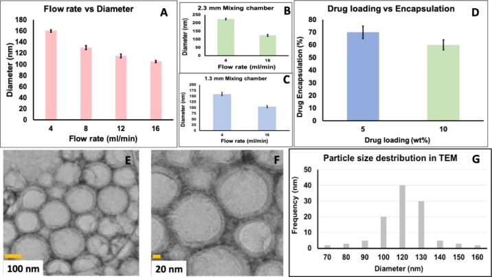
MIVM is another one-step approach to prepare RLPHNPs. In this approach, four turbulent jets of solvent and antisolvent enter tangentially in a mixing chamber with 90° offset. The mixing efficiency is highest when opposing streams have equal contributions and flow rates.26 Hence, production parameters such as flow rates and size of the mixing chambers affect the size of LPHNPs. Accordingly, different flow rates have been applied to all the four streams and the corresponding particle size is shown in Figure 4A. Unlike microfluidics, flow rates do not affect significantly the size of the nanoparticle. However, the trend of decrease in particle size with increasing the flow rates is followed in the MIVM technique also. Along with the flow rates, the size of the mixing chambers also affects the size of the RLPHNPs. Figure 4B,C shows variation in the size of the RLPHNPs corresponding to the large (2.3 mm) and small size (1.3 mm) of the mixing chamber. It is clear from Figure 4B,C that the large mixing chamber yielded a bigger RLPHNP particle size of ∼250–150 nm, whereas the small mixing chamber leads to the formation of smaller particles of 80–120 nm. Therefore, it is clear from Figure 4A–C that flow rates of 12 or 16 mL/min and a 1.3 mm mixing chamber would be ideal for the RLPHNPs by the MIVM device.
Figure 4.
Variation in particle size corresponding to (A) different flow rates, (B) large mixing chamber, and (C) small mixing chamber. (D) Encapsulation efficiency of RLPHNPs, (n = 3). (E,F) TEM images of RLPHNPs; (G) particle size distribution of RLPHNPs.
To analyze the encapsulation efficiency of the RLPHNPs, different amounts of rifampicin were loaded inside the PLGA core and their corresponding encapsulation efficiency was measured. Figure 4D displays the encapsulation efficiency of RLPHNPs with respect to the 5 and 10% of rifampicin, which is ∼70 and 60%, respectively. Figure 4E,F depicts the TEM micrograph of the RLPHNPs synthesized using a 12 mL/min flow rate and 1.3 mm mixing chamber. Figure 4E,F indicates that RLPHNPs are spherical with two distinct layers. A relatively dense inside layer is the PLGA polymer core, whereas the outside layer represents the 1, 2-Distearoyl-sn-glycero-3-phosphoethanolamine-Poly(ethylene glycol) (DSPE-PEG) lipid shell, which can be clearly seen in Figure 4F. The particle size distribution of these nanoparticles (Figure 4G) shows that the particle size of RLPHNPs ranges from 110 to 130 nm, which is in in good agreement with the DLS measurement.
Synthesis of RLPHNP by a 3D Printed MIVM with the Herringbone Pattern
As mentioned in the previous section, MIVM has been used to improve the efficiency and time of mixing a lipid and polymeric solution by creating a turbulent vortex action at the center of the device. However, the flows along the inlets in MIVM are fairly laminar. In order to create a more turbulent flow in the inlets, a herringbone design has been implemented.27 The herringbone mixer is a passive mixer design which is capable of inducing a transverse flow in the form of two counter rotating vortices as the primary mixing mechanism.23,28 Unlike microfluidics and MIVM, there are many other parameters such as herringbone spacing, outlet mixing efficiency, average velocity, and average vorticity which affect the particle size of RLPHNPs. Table 1 gives the outlet mixing efficiency, average velocity, and average vorticity value at different herringbone spacings.
Table 1. Mixing Efficiency, Average Velocity, and Average Vorticity Value at Different Herringbone Spacings.
| herringbone spacing | outlet mixing efficiency (%) | average velocity (m/s) | average vorticity (1/s) |
|---|---|---|---|
| no herringbone | 99.18 | 0.04300 | 25.90 |
| 900 μm | 99.49 | 0.04253 | 28.35 |
| 750 | 99.95 | 0.04258 | 28.40 |
| 600 | 99.95 | 0.04266 | 28.49 |
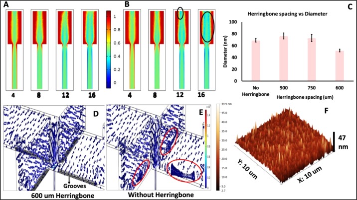
As can be seen from Table 1, the values of outlet mixing efficiency and average velocity hardly change with respect to the herringbone spacing. Figure 5A,B shows the concentration slices of the mixing chamber and outlet of the MIVM device with and without the herringbone pattern, respectively, at different flow rates. The concentration slices are scaled from 0 to 1, where 0 and 1 are separate opposing sample solutions and a perfect mixing efficiency at the outlet would result in a value of 0.5. As can be seen from Figure 5A,B, mixing was observed to be more efficient at the outlet and at the center of the mixing chamber than the corners and edges of the mixing chamber. In addition to this, the area of efficient mixing increases with increase in the flow rates. This indicates that higher flow rates such as 12 and 16 mL/min are desirable for nanoparticle fabrication. There is no significant difference observed between mixing efficiencies of the MIVM device with and without the herringbone pattern; however, some blue patches were observed at the corners of the mixing chamber (encircled in Figure 5B), which may correspond to a slight lower value of mixing efficiency of MIVM without the herringbone device.
Figure 5.
Concentration slices of MIVM (A) with and (B) without the herringbone device; (C) variation in particle size corresponding to the herringbone spacing (n = 3). Vorticity streamlines of the mixing chamber of the MIVM (D) without the herringbone and (E) with the herringbone at 16 mL/min flow rate; (F) AFM image of RLPHNPs.
As can be noted from Table 1, average vorticity values are considerably higher for the herringbone-patterned MIVM devices. Vorticity describes the local spinning motion of the continuum near the specific area/field (the tendency of something to rotate).29 The grooves in the herringbone pattern create helical motions of the moving fluid inside the microchannel. This leads to the twisting patterns of two liquid channels into each other at that point, resulting in a higher vorticity value, which is also depicted by Figure 5D,E.30 The MIVM without the herringbone pattern shows uneven distribution of vorticity values (encircled in Figure 5E). On the other hand, the herringbone-patterned MIVM showed more prominent vorticity streamlines with uniform distribution.
Figure 5C gives the variation in the particle size of RLPHNPs corresponding to different herringbone spacings at the flow rate of 16 mL/min. It is clear from Figure 5 that a tight herringbone spacing of 600 μm leads to the formation of the smallest RLPHNPs. This can be attributed to the highest mixing efficiency and vorticity values. Figure 5D shows the atomic force microscopy (AFM) image of the RLPHNPs synthesized with 600 μm and 16 mL/min flow rate. Figure 5D indicates the particle size of ∼53 nm, which matches well with the DLS measurement.
Comparison among all Three Methods of LPHNP Synthesis
Finally, to compare all the three synthesis methods, synthesis of myristic acid-loaded LPHNPs has been carried out by microfluidics, MIVM, and MIVM with herringbone methods. In this case, all the synthesis and production parameters were kept constant for all the methods. On the basis of the obtained results, flow rates of 12 mL/min and drug amount of 5% have been employed during the synthesis in all the three methods. In the case of MIVM, a 1.3 mm mixing chamber has been used, whereas 600 μm spacing is used for MIVM with the herringbone pattern. The synthesis has been repeated five times for each method and the size of the resulting myristic acid-loaded LPHNPs have been measured and are given in Figure 6. Particle sizes for all methods were observed to be colloidally stable over 7 days.
Figure 6.
(A) Variation in particle size and (B) polydispersity of myristic acid-loaded LPHNPs corresponding to different synthesis methods.
From Figure 6, the average particle size obtained for microfluidics, MIVM, and MIVM with the herringbone pattern device is 107, 199, and 74.5 nm, respectively. It is clear from Figure 6A,B that the herringbone-patterned MIVM methods yield the smallest particle size with uniform size distribution. It may be due to the development of vortices in the grooves, which ultimately reduce the relative volume of fluid that moved across the channel at high flow rates.31. In addition to this, it can be noted from Figure 6A that the herringbone-patterned MIVM method showed more reproducibility and repeatability in the LPHNP synthesis than the other two methods. This can be attributed to the good mixing efficiencies and controlled microvortices taking place at the herringbone pattern grooves.32 Hence, the 3D printed herringbone-patterned MIVM device represents a better approach for the synthesis of LPHNPs. Moreover, the herringbone-patterned MIVM method appears to be general. The herringbone-patterned reactor, microfluidics, and MIVM were used to create lipid polymer-encapsulated quantum dots and the pattern was the same as reported above. The herringbone-pattered MIVM produced the most consistent particle sizes.
Conclusions
LPHNPs have been synthesized by microfluidics, MIVM, and 3D printed herringbone-patterned MIVM methods. Initial experiments indicate that higher flow rates of ∼12 mL/min yield smaller nanoparticles. However, lesser drug loading (5%) gives better drug encapsulation. Considering these parameters, myristic acid-loaded LPHNPs have been synthesized by all the three methods, keeping all the parameters constant. The results indicated that the 3D printed herringbone-patterned MIVM methods give the smallest sized LPHNPs with uniform size distribution, which is attributed to the enhanced mixing efficiency and vorticity offered by this device. Along with this, the 3D printed herringbone-patterned device was observed to give more reproducible and repeatable results as compared to the other two methods. This simple, cost-effective, and most reproducible method might be applicable for the controlled synthesis of LPHNPs and rapid screening of nano-drug-delivery systems.
Materials and Methods
The PLGA polymer was provided by Akina Chemicals (West Lafayette, IN, USA). The DSPE-PEG amine was supplied by Avanti Polar Lipids (Alabaster, AL, USA). Lecithin (soybean, refined) was supplied by Alfa Aesar. 4% by weight aqueous ethanol, acetonitrile, and chloroform were purchased from Sigma-Aldrich (St. Louis, MO, USA). For device fabrication, silicon wafers were obtained from Silicon Quest International (San Jose, CA, USA) Inc. SU-8-2035 and SU-8 developers were obtained from Microchem Corporation (Westborough, MA, USA). Sylgard 181 Silicone Elastomer Base was obtained from Dow Corning (Midland, Michigan, USA).
Synthesis of RLPHNPs
The schematic used for the synthesis of RLPHNPs is shown in Figure 7. Two separate solutions were used for the synthesis of RLPHNPs. The first solution was the PLGA polymer dissolved in acetonitrile (1 mg/mL) solution. An appropriate amount of rifampicin was mixed with this PLGA solution (5, 10, and 20%), which forms the core of the RLPHNPs. The second solution was lecithin/DESPE-PEG (1:2.5) lipid solution, which forms the shell of the nanoparticle. In the case of the lipid solution, the formulations for these methods differ slightly. In the case of microfluidics and MIVM with herringbone methods, DSPE-PEG/lecithin was dissolved in chloroform first. After evaporating the chloroform in vacuum, the residue was dissolved in 4% ethanol and heated to a temperature of 65 °C with a hot plate. In the MIVM method, DSPE-PEG/lecithin was dissolved in water and was not heated at 65 °C as this formulation was considered to be temperature-independent. These two solutions were then applied to the inlets of microfluidics, MIVM, and 3D printed herringbone-patterned MIVM devices with variable flow rates. The obtained nanoparticles were then washed with distilled water using 30 kDa pore tangential flow filtration MicroKros apparatus.
Figure 7.
Schematic for LPHNP synthesis.
Synthesis of Myristic Acid-Loaded LPHNPs
In the case of myristic acid-loaded LPHNPs, all the synthesis parameters were kept constant for all the three methods. Two solutions were prepared for the synthesis: solution-A consisted of the PLGA polymer core dissolved in acetonitrile (1 mg/mL) along with an appropriate amount of myristic acid (5%). Solution-B is the lipid-shell solution. To prepare this solution, chloroform containing dissolved lecithin was added to the chloroform containing DSPE-PEG solution. The resulting solution was then placed in a vacuum chamber to allow chloroform to evaporate, leaving a thin film of lecithin and DSPE-PEG. Then, the resulting dry residue were suspended in 4% ethanol before the solution was heated to 65 °C. These two solutions were then applied to the inlets of microfluidics, MIVM, and a 3D printed MIVM with the herringbone-patterned device at a fixed rate of 12 mL/min. Finally, synthesized nanoparticles were then washed with distilled water and filtered using a 30 kDa pore tangential flow filtration MicroKros apparatus. All the LPHNPs were characterized by DLS, AFM, and TEM imaging techniques.
Characterization Techniques
The average particle size of the nanoparticles was calculated using DLS technique on NanoBrook 90Plus Particle Analyzer. Each DLS measurement is repeated at least three times and mean value is presented in the report. Standard deviation calculated from these values have been shown as error bars. AFM analysis was done using a 5500 Atomic Force Microscope by Keysight Technologies. TEM imaging of the nanoparticles was performed at the NASA AMES facility using a Hitachi H-9500 System (operating voltage of the system was 300 kV). COMSOL software was utilized to stimulate and analyze various fluidic properties of the herringbone-patterned 3D printed MIVM device. Encapsulation efficiency was calculated from % EE = [(drug added – free “unentrapped drug”)/drug added] × 100. The drug loading is 10 or 15% the weight of the PLGA, which represents 10 or 15% drug loading. These measurements were performed in triplicate, and the standard deviation calculated from the obtained results have been shown in the figures in the form of error bars.
The authors declare no competing financial interest.
References
- Hamers R. J. Nanomaterials and Global Sustainability. Acc. Chem. Res. 2017, 50, 633–637. 10.1021/acs.accounts.6b00634. [DOI] [PubMed] [Google Scholar]
- Marchesan S.; Prato M. Nanomaterials for (Nano)medicine. ACS Med. Chem. Lett. 2013, 4, 147–149. 10.1021/ml3003742. [DOI] [PMC free article] [PubMed] [Google Scholar]
- Liu Y.; Zhou G.; Liu K.; Cui Y. Design of Complex Nanomaterials for Energy Storage: Past Success and Future Opportunity. Acc. Chem. Res. 2017, 50, 2895–2905. 10.1021/acs.accounts.7b00450. [DOI] [PubMed] [Google Scholar]
- Khan A.; Wen Y.; Huq T.; Ni Y. Cellulosic Nanomaterials in Food and Nutraceutical Applications: A Review. J. Agric. Food Chem. 2018, 66, 8–19. 10.1021/acs.jafc.7b04204. [DOI] [PubMed] [Google Scholar]
- Lowry G. V.; Gregory K. B.; Apte S. C.; Lead J. R. Transformations of Nanomaterials in the Environment. Environ. Sci. Technol. 2012, 46, 6893–6899. 10.1021/es300839e. [DOI] [PubMed] [Google Scholar]
- Shi J.; Votruba A. R.; Farokhzad O. C.; Langer R. Nanotechnology in Drug Delivery and Tissue Engineering: From Discovery to Applications. Nano Lett. 2010, 10, 3223–3230. 10.1021/nl102184c. [DOI] [PMC free article] [PubMed] [Google Scholar]
- Mohammadi M. R.; Nojoomi A.; Mozafari M.; Dubnika A.; Inayathullah M.; Rajadas J. Nanomaterials engineering for drug delivery: a hybridization approach. J. Mater. Chem. B 2017, 5, 3995–4018. 10.1039/c6tb03247h. [DOI] [PubMed] [Google Scholar]
- Garg N. K.; Tyagi R. K.; Sharma G.; Jain A.; Singh B.; Jain S.; et al. Functionalized Lipid–Polymer Hybrid Nanoparticles Mediated Codelivery of Methotrexate and Aceclofenac: A Synergistic Effect in Breast Cancer with Improved Pharmacokinetics Attributes. Mol. Pharm. 2017, 14, 1883–1897. 10.1021/acs.molpharmaceut.6b01148. [DOI] [PubMed] [Google Scholar]
- Clawson C.; Ton L.; Aryal S.; Fu V.; Esener S.; Zhang L. Synthesis and Characterization of Lipid–Polymer Hybrid Nanoparticles with pH-Triggered Poly(ethylene glycol) Shedding. Langmuir 2011, 27, 10556–10561. 10.1021/la202123e. [DOI] [PMC free article] [PubMed] [Google Scholar]
- Zhang J.; Wang D.; Wu Y.; Li W.; Hu Y.; Zhao G.; et al. Lipid–Polymer Hybrid Nanoparticles for Oral Delivery of Tartary Buckwheat Flavonoids. J. Agric. Food Chem. 2018, 66, 4923–4932. 10.1021/acs.jafc.8b00714. [DOI] [PubMed] [Google Scholar]
- Yao C.; Wu M.; Zhang C.; Lin X.; Wei Z.; Zheng Y.; et al. Photoresponsive lipid-polymer hybrid nanoparticles for controlled doxorubicin release. Nanotechnology 2017, 28, 255101. 10.1088/1361-6528/aa702a. [DOI] [PubMed] [Google Scholar]
- Wu B.; Yu P.; Cui C.; Wu M.; Zhang Y.; Liu L.; et al. Folate-containing reduction-sensitive lipid–polymer hybrid nanoparticles for targeted delivery of doxorubicin. Biomater. Sci. 2015, 3, 655–664. 10.1039/c4bm00462k. [DOI] [PubMed] [Google Scholar]
- Zhang L.-J.; Wu B.; Zhou W.; Wang C.-X.; Wang Q.; Yu H.; et al. Two-component reduction-sensitive lipid–polymer hybrid nanoparticles for triggered drug release and enhanced in vitro and in vivo anti-tumor efficacy. Biomater. Sci. 2017, 5, 98–110. 10.1039/c6bm00662k. [DOI] [PubMed] [Google Scholar]
- Zhang L.; Zhang L. Lipid–polymer hybrid nanoparticles: synthesis, characterization and applications. Nano LIFE 2010, 01, 163–173. 10.1142/s179398441000016x. [DOI] [Google Scholar]
- Feng Q.; Zhang L.; Liu C.; Li X.; Hu G.; Sun J.; et al. Microfluidic based high throughput synthesis of lipid-polymer hybrid nanoparticles with tunable diameters. Biomicrofluidics 2015, 9, 052604. 10.1063/1.4922957. [DOI] [PMC free article] [PubMed] [Google Scholar]
- Lee C.-Y.; Chang C.-L.; Wang Y.-N.; Fu L.-M. Microfluidic Mixing: A Review. Int. J. Mol. Sci. 2011, 12, 3263–3287. 10.3390/ijms12053263. [DOI] [PMC free article] [PubMed] [Google Scholar]
- Fang R. H.; Chen K. N. H.; Aryal S.; Hu C.-M. J.; Zhang K.; Zhang L. Large-Scale Synthesis of Lipid–Polymer Hybrid Nanoparticles Using a Multi-Inlet Vortex Reactor. Langmuir 2012, 28, 13824–13829. 10.1021/la303012x. [DOI] [PubMed] [Google Scholar]
- Bhattacharjee N.; Urrios A.; Kang S.; Folch A. The upcoming 3D-printing revolution in microfluidics. Lab Chip 2016, 16, 1720–1742. 10.1039/c6lc00163g. [DOI] [PMC free article] [PubMed] [Google Scholar]
- van Ingen J.; Aarnoutse R. E.; Donald P. R.; Diacon A. H.; Dawson R.; Plemper V. B. G.; et al. Why Do We Use 600 mg of Rifampicin in Tuberculosis Treatment?. Clin. Infect. Dis. 2011, 52, e194–e199. 10.1093/cid/cir184. [DOI] [PubMed] [Google Scholar]
- Praagman J.; Beulens J. W.; Alssema M.; Zock P. L.; Wanders A. J.; Sluijs I.; et al. The association between dietary saturated fatty acids and ischemic heart disease depends on the type and source of fatty acid in the European Prospective Investigation into Cancer and Nutrition–Netherlands cohort. Am. J. Clin. Nutr. 2016, 103, 356–365. 10.3945/ajcn.115.122671. [DOI] [PubMed] [Google Scholar]
- Liu Z.; Ramezani M.; Fox R. O.; Hill J. C.; Olsen M. G. Flow Characteristics in a Scaled-up Multi-inlet Vortex Nanoprecipitation Reactor. Ind. Eng. Chem. Res. 2015, 54, 4512–4525. 10.1021/ie5041836. [DOI] [Google Scholar]
- Shi Y.; Cheng J. C.; Fox R. O.; Olsen M. G. Measurements of turbulence in a microscale multi-inlet vortex nanoprecipitation reactor. J. Micromech. Microeng. 2013, 23, 075005. 10.1088/0960-1317/23/7/075005. [DOI] [Google Scholar]
- Williams M. S.; Longmuir K. J.; Yager P. A practical guide to the staggered herringbone mixer. Lab Chip 2008, 8, 1121–1129. 10.1039/b802562b. [DOI] [PMC free article] [PubMed] [Google Scholar]
- Chan L.; Nguyen A.; Bokare A.; Erogbogbo F. Cost Effective 3D Printed Device for Tuberculosis Nanoformulation Manufacturing. MRS Adv. 2018, 3, 2943. 10.1557/adv.2018.472. [DOI] [Google Scholar]
- Ward K.; Fan Z. H. Mixing in microfluidic devices and enhancement methods. J. Micromech. Microeng. 2015, 25, 094001. 10.1088/0960-1317/25/9/094001. [DOI] [PMC free article] [PubMed] [Google Scholar]
- Hickey J. W.; Santos J. L.; Williford J.-M.; Mao H.-Q. Control of Polymeric Nanoparticle Size to Improve Therapeutic Delivery. J. Controlled Release 2015, 219, 536–547. 10.1016/j.jconrel.2015.10.006. [DOI] [PMC free article] [PubMed] [Google Scholar]
- Kwak T. J.; Nam Y. G.; Najera M. A.; Lee S. W.; Strickler J. R.; Chang W.-J. Convex Grooves in Staggered Herringbone Mixer Improve Mixing Efficiency of Laminar Flow in Microchannel. PLoS One 2016, 11, e0166068 10.1371/journal.pone.0166068. [DOI] [PMC free article] [PubMed] [Google Scholar]
- Hama B.; Mahajan G.; Fodor P. S.; Kaufman M.; Kothapalli C. R. Evolution of mixing in a microfluidic reverse-staggered herringbone micromixer. Microfluid. Nanofluid. 2018, 22, 54. 10.1007/s10404-018-2074-0. [DOI] [Google Scholar]
- Speziale C. G. On the advantages of the vorticity-velocity formulation of the equations of fluid dynamics. J. Comput. Phys. 1987, 73, 476–480. 10.1016/0021-9991(87)90149-5. [DOI] [Google Scholar]
- Xu Z.; Lu C.; Riordon J.; Sinton D.; Moffitt M. G. Microfluidic Manufacturing of Polymeric Nanoparticles: Comparing Flow Control of Multiscale Structure in Single-Phase Staggered Herringbone and Two-Phase Reactors. Langmuir 2016, 32, 12781–12789. 10.1021/acs.langmuir.6b03243. [DOI] [PubMed] [Google Scholar]
- Damiati S.; Kompella U. B.; Damiati S. A.; Kodzius R. Microfluidic Devices for Drug Delivery Systems and Drug Screening. Genes 2018, 9, 103. 10.3390/genes9020103. [DOI] [PMC free article] [PubMed] [Google Scholar]
- Marschewski J.; Jung S.; Ruch P.; Prasad N.; Mazzotti S.; Michel B.; et al. Mixing with herringbone-inspired microstructures: overcoming the diffusion limit in co-laminar microfluidic devices. Lab Chip 2015, 15, 1923–1933. 10.1039/c5lc00045a. [DOI] [PubMed] [Google Scholar]


