Abstract
The epicardial adipose tissue (EAT) refers to the deposition of adipose tissue fully enclosed by the pericardial sac. EAT has a complex mixture of adipocytes, nervous tissue, as well as inflammatory, stromal and immune cells secreting bioactive molecules. This heterogeneous composition reveals that it is not a simply fat storage depot, but rather a biologically active organ that appears playing a “dichotomous” role, either protective or proinflammatory and proatherogenic. The cardiac magnetic resonance (CMR) allows a clear visualization of EAT using a specific pulse sequence called steady-state free precession. When abundant, the EAT assumes a pervasive presence not only covering the entire epicardial surface but also invading spaces that usually are almost virtual and separating walls that usually are so close each other to resemble a single wall. To the best of our knowledge, this aspect of cardiac anatomy has never been described before. In this pictorial review, we therefore focus our attention on certain cardiac areas in which EAT, when abundant, is particularly intrusive. In particular, we describe the presence of EAT into: (a) the interatrial groove, the atrioventricular septum, and the inferior pyramidal space, (b) the left lateral ridge, (c) the atrioventricular grooves, and (d) the transverse pericardial sinus. To confirm the reliability in depicting the EAT distribution, we present CMR images side-by-side with corresponding anatomic specimens.
Keywords: Cardiac magnetic resonance, epicardial adipose tissue, multimodality imaging
INTRODUCTION
The adipose tissue around the heart includes two main depots: the epicardial adipose tissue (EAT), which refers to the deposition of adipose tissue fully enclosed by the pericardial sac and the paracardial adipose tissue (PAT), which refers to the fat depot external to the pericardium within the mediastinum. They are quite different, not only anatomically but also from an embryological and biochemical point of views.[1,2] The EAT constitutes nearly 20% of the cardiac weight, while the PAT may have variable extension representing up to 50% of the myocardial mass [Figure 1].
Figure 1.
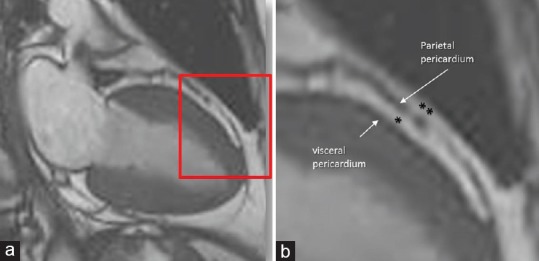
(a)Cardiac magnetic resonance cine-sequence still frame obtained with steady-state free precession (CMR SSFP) sequence. The area in the red box is magnified in panel B. (b) These images clearly show the parietal and the visceral pericardium. The epicardial adipose tissue is confined between the visceral and parietal pericardium, i.e., fully enclosed in the pericardial sac (*), while the paracardial adipose tissue (**) is external to pericardium
EAT contains a complex mixture of adipocytes, nervous tissue, as well as inflammatory, stromal, and immune cells secreting bioactive molecules. This heterogeneous composition reveals that it is not a simply fat storage depot, but rather a biologically active organ that appears playing a “dichotomous” role, either protective or proinflammatory and proatherogenic.[3] Indeed, the absence of a connective fascia or similar structure separating EAT from the vessels makes it in direct contact with the adventitia of coronary arteries. It is reasonable to postulate that EAT may interact locally and modulate the coronary arteries changes through the paracrine secretion of pro-inflammatory and pro-atherogenic molecules.[3] On the other hand, in a delicate balance, EAT produces also protective, anti-inflammatory and antiatherogenic adipokines, such as adiponectin and vasodilator anti-inflammatory and angiogenic factors such as adrenomedullin.[3]
Furthermore, surrounding the major coronary arteries, EAT provides a mechanical protection of the coronary arteries, buffering them against the torsion induced by the arterial pulse wave and cardiac contraction. In addition, it has been suggested that EAT could act as heat-generating tissue around the heart protecting it against hypothermia.[4] Finally, since EAT has a higher rates of fatty acid uptake and secretion that other visceral fat depots, it may also act as a buffer absorbing fatty acid and protecting the heart against high fatty acid level and, at the same time, as local energy source. The role of EAT on cardiac biology and its relation with atherosclerotic and nonatherosclerotic cardiovascular diseases has been extensively discussed by Antonopoulos et al. in a recent review.[5]
Noninvasive imaging techniques may visualize the EAT, although with different efficacy. Two-dimensional echocardiography visualizes EAT as an almost echo-free space between the outer wall of the myocardium and the visceral layer of the pericardium.[6] This imaging technique however has a limited field of view, providing only thin tomographic slices of the heart and the surrounding EAT. Three-dimensional echocardiography enlarges the field of view adding the Z-dimension. However, the resolution power of this imaging tool does not yet allow clear distinction between two tissues (i.e., adipose and muscular) that have similar acoustic impedance.
Computed tomography (CT), on the other hand, provides high spatial resolution and true volume coverage of the heart; therefore, it constitutes an attractive approach to identify EAT on the basis of thresholds of attenuation.[7] However, differences in attenuation do not always permit a clear differentiation between myocardium and EAT, and quite often, borders of EAT are rather indistinct. Moreover, a limitation of CT remains the exposure to ionizing radiation.
Using a specific pulse sequence called balanced steady-state free precession (SSFP), cardiac magnetic resonance (CMR) imaging allows a clear distinction between muscular and adipose tissue. This sequence provides a high signal/noise ratio and an optimal blood/myocardial contrast, which allows a precise definition of the endocardial borders. Furthermore, in SSFP, the strength of the signal originating from different tissues depends on T1/T2 ratio. Water (blood) and fat have the same high T1/T2 ratio, then both tissues produce a very high signal. On the contrary, the muscular tissue has a low T1/T2 ratio and produces weak signal. These sequences are therefore capable of distinguishing the adipose tissue from atrial and ventricular muscular walls much clearer than any other noninvasive imaging technique. Therefore, CMR is an ideal imaging tool for investigating the presence and extension of the EAT.[8]
We noticed that, when abundant, the EAT assumes a pervasive presence not only covering the entire epicardial surface but also invading spaces that usually are almost virtual, and separating walls that usually are so close each other to resemble a single wall. To the best of our knowledge, this particular aspect of anatomy of EAT and its spatial relationship with several cardiac structures has never been described.
In this pictorial review, we choose several examples of patients who underwent CMR and in whom EAT was particularly abundant focusing our attention on certain cardiac areas in which EAT is particularly invasive distorting cardiac structures and revealing hidden anatomic details. In particular, we observe as EAT may deeply penetrate into: (a) the interatrial groove, the atrioventricular septum (AVS), and the inferior pyramidal space (IPS), (b) the left lateral ridge (LLR), (c) the atrioventricular grooves, and (d) the transverse pericardial sinus (TPS).
THE INTERATRIAL GROOVE (WATERSTON'S GROOVE)
From an embryological point of view, the interatrial septum (IAS) includes two components: the septum primum (SP) and the septum secundum (SS). Anatomists however describe the IAS as a membrane, which separates the atrial cavities. Consequently, any puncture, incision, or removal of the true IAS must create a communication between the right and left cavities. Defined in such a way, the IAS is limited to the floor of the fossa ovalis (FO), which is the embryonic SP and its immediate borders. The superior–posterior wall (the embryonic SS) is actually a two-layer muscular structure formed by an extensive enfolding of the atrial wall between the venous component of the right atrium and the right pulmonary veins. Externally, this fold (also called interatrial or Waterston's groove) is filled with EAT and frequently contains the artery supplying the sinus node. It surrounds the FO extending superiorly, posteriorly, and inferiorly. Often this enfolding is almost virtual, and the two atrial walls appear as a single wall. However, when EAT is abundant, it penetrates deeply into the fold between the atrial walls, and the anatomic characteristics of this enfolding are evident. The four-chamber cut of CMR cine sequences beautifully represents this particular architectural arrangement [Figure 2a]. In a short-axis cut [Figure 2b] and in more longitudinal anterior and posterior cuts [Figure 2b–d], the FO disappears and this enfolding assumes a “three-layered” aspect formed by right atrial wall, adipose layer, and left atrial wall. These images demonstrate that the interatrial groove extends posteriorly and inferiorly in-between to the inferior margin of FO and the AV junction. The clinical implications of this peculiar anatomical architecture are relevant. Several left-sided percutaneous interventions and arrhythmias ablations procedures require puncturing the IAS. According to this anatomical architecture, the only site for a safe transseptal crossing is through the FO (the true IAS), and its variable size should be taken into account. A puncture through the superior–posterior–inferior folding is in reality a puncture through the atrial wall and may cause pericardial effusion and eventually cardiac tamponade [Figure 3].
Figure 2.
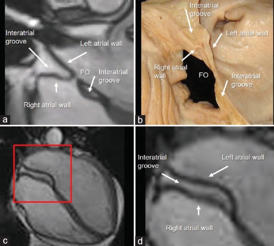
(a) Cardiac magnetic resonance steady-state free precession still frames. The images clearly show that the interatrial groove (the embryonic septum secundum) is made up by the folding of right and left atrial walls. (b) Anatomic specimen displayed in similar view. (c) In a more posterior cut, the fossa ovalis disappears and this enfolding assumes a “three layered” aspect (see text). (d) Magnified image of the red box of panel c
Figure 3.
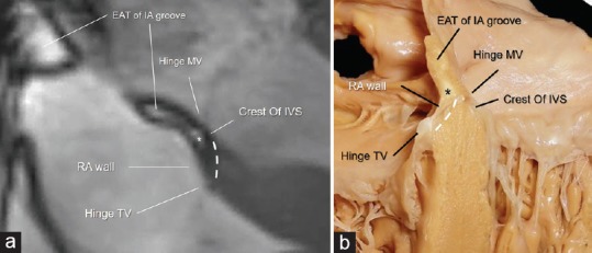
(a) CMR SSFP still frames showing the AVS (dotted line) sited in between the hinge of TV and the hinge of MV. The image clearly shows the EAT (asterisk) in between the RA wall and the crest of IVS. This particular anatomical arrangement has been named “atrio-ventricular muscular sandwich.” (b) Anatomic specimen showing the offset arrangement between the hinges of the tricuspid and mitral valves (arrows), the AVS (dotted line), and the EAT (asterisk) (see text). IA = Interatrial. AVS = Atrioventricular septum, CMR SSFP = Cardiac magnetic resonance steady-state free precession, TV = Tricuspid valve, MV = Mitral valve, RA = Right atrial, IVS = Interventricular septum, EAT = Epicardial adipose tissue
This particular anatomical architecture has been also source of misnomers encountered in literature.
First, the old classification of septal aneurysm as “limited” to the FO or involving the entire septum[9] no longer makes sense. The septal aneurysm is always limited to the FO since it is inconceivable that a three-layered muscular/adipose structure that forms the SS could be involved in an aneurysmal formation.
Second, the so-called lipomatous hypertrophy of IAS is not a proliferation of adipose tissue that occurs within the IAS, as often described in literature, but an extracardiac accumulation within the interatrial groove.[10]
Third, the subtypes of interatrial septal communications, i.e., superior sinus venous and inferior sinus venosus types, ostium primum, and unroofed coronary sinus should be renamed as interatrial extra septal communications since the true IAS is intact.
THE ATRIOVENTRICULAR JUNCTION AND THE INFERIOR PYRAMIDAL SPACE
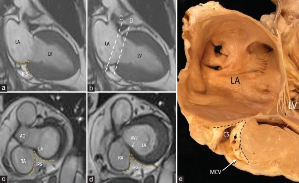
The atrio-ventricular junction (AVJ) is a characteristic area where septal components of the atria and ventricles join with the mitral and tricuspid leaflets. This region is also known with the Latin name of “crux cordis”. The most peculiar anatomical characteristic of this area is the hinge line of the tricuspid septal leaflet that is more apically displaced as compared to the corresponding mitral leaflet. Given the offset valvular arrangement, the part of the heart that separates the right atrial cavity from the left ventricular cavity is known as the AVS and has been described as being entirely muscular.[11] More detailed anatomical and histological studies, however, have shown that this structure is more complex than previously thought because it is formed by the atrial wall on the right side and by the crest of the interventricular septum on left side with in between a spot of EAT. For this particular anatomical arrangement, the anatomists renamed this area as “atrio-ventricular muscular sandwich” whereby the EAT represents the “meat” in the sandwich.[12] Usually, the EAT inside the AVS is not visible being below the resolution power of CMR (as well as of echocardiography and CT). However, in patients with abundant EAT, it can be seen as a spot of adipose tissue below the inferior interatrial groove. In some case, the two depots may join together [Figure 4]. The EAT of atrioventricular muscular sandwich is an extension of the EAT depot sited into the IPS. This area is located at the convergence of interatrial, interventricular, right, and left atrioventricular grooves, and it is bordered on two sides by the left and right atrial walls, and inferiorly by the crest of ventricular wall. The IPS contains numerous important structures including arteries, veins, and nerves.[13] The most important arterial vessel running through the IPS is the atrioventricular nodal artery [Figure 4].
Figure 4.
(a-d) CMR SSFP still frame. In the panel a is shown a two-chamber longitudinal plane, showing on the inferior-posterior aspect of the heart, the IPS filled with EAT (yellow dotted line). The two dotted lines in panel b refer to the two short axis planes shown in panel c and d respectively. Panel c shows a short axis plane with the IPS bordered by the right and left atrial walls, while the panel d shows a lower short axis plane where the IPS is bordered by the right atrial wall and by the crest of interventricular septum (see text). Panel (e) is an anatomic specimen displayed in similar fashion as the image on panel a. The IPS is located between the two dotted lines. Within it there are the CS, the MCV and a coronary artery (short arrow). RA = Right atrium, LA = Left atrium, LV = Left ventricle, Ao = Aorta, AVJ = Atrioventricular junction, MCV = Middle cardiac vein, CS = Coronary sinus, EAT = Epicardial adipose tissue, CMR SSFP = Cardiac magnetic resonance steady-state free precession, IPS = Inferior pyramidal space
LEFT LATERAL RIDGE
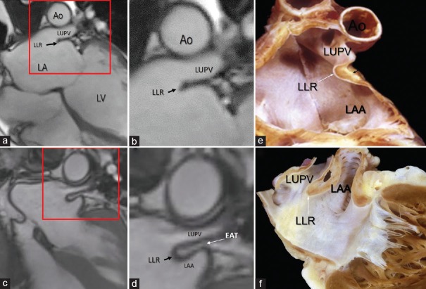
The LLR [Figure 5a–f] is a muscular protuberance into the left atrial cavity between orifice of the left atrial appendage and the left pulmonary veins. Shape of its cross-sectional profile is highly variable. Anatomic studies have shown that this muscular ridge is not a muscular crest but rather a fold of the atrial wall between the LAA and left upper pulmonary vein.[14] The folded nature of the LLR may be almost invisible, and it appears usually as a single ridge on the endocardial surface since the two walls lie adjacent to each other and none of available noninvasive imaging techniques has a spatial resolution power of discerning the two atrial walls [Figure 5a and b]. In some cases, the LLR may end with a rounded shape; in the early days of transesophageal echocardiography, this peculiar anatomic architecture was named the “Q-tip sign.”[15] CMR reveals that this round end is filled by adipose tissue [Figure 5c and d]. In the past, this peculiar architecture was also misinterpreted for a thrombotic mass and resulted in patients being prescribed anticoagulation therapy with warfarin (Coumadin) and became known as “coumadin ridge”. In patients with abundant EAT, the adipose tissue penetrates between the two atrial wall clearly revealing its folded nature as beautifully demonstrated by CMR. The EAT occupying this folding contains arterial vessels, nerve bundles and the oblique vein of Marshall or its remnant that descends into the coronary sinus (from here derives the name of Marshall's ridge adopted by electrophysiologists).
Figure 5.
CMR SSFP still frame. The area in the red box in the panel (a) is magnified in panel (b). The images show a single ridge (LLR) formed by the two walls so close each other that cannot be distinguished. (c) The area in the red box is magnified in panel (d). In this patient with abundant EAT, the images clearly show the folding of the left atrial wall between the LAA and the LUPV protruding into the left atrium. Panels (e) and f (f) are cuts through anatomical specimens showing the fold of the atrial wall that makes up the LLR. Ao = Aorta, LA = Left atrium, LAA = Left atrial appendage, LUPV = Left upper pulmonary vein, CMR SSFP = Cardiac magnetic resonance steady-state free precession, LLR = Left lateral ridge, EAT = Epicardial adipose tissue
THE LEFT ATRIOVENTRICULAR GROOVE AND THE MITRAL ANNULUS
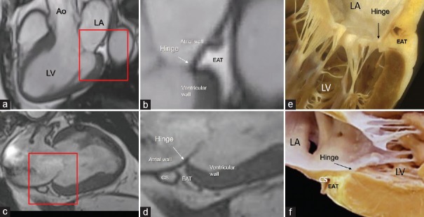
The left atrioventricular groove lies near the posterior–lateral segment of mitral annulus. This portion of the annulus sustains the posterior leaflet and roughly portrayed as a letter “C” extending posteriorly from the left to the right commissures. It is made up by the convergence of four anatomical tissues: the atrial wall, the leaflet hinge, the crest of the free wall of left ventricle, and the EAT occupying the atrioventricular groove. A band of connective tissue (the fibrous annulus) is supposed to “glue” these three components together. However, this band is not continuous and may have different consistency and robustness. In those parts in which this fibrous band is deficient, the posterior leaflet inserts directly on the ventricular myocardium.[16] This anatomical arrangement allows the posterior annulus following the myocardial contraction and relaxation, playing a fundamental role in the sphincter action. The EAT fills the adjacent atrioventricular groove, surrounding the circumflex coronary artery and the coronary sinus. Notably, the EAT from the atrioventricular groove penetrates deeply on the crest of ventricular myocardium up to the base of posterior leaflet to form the hinge line. Thus EAT is undoubtedly part of posterior mitral annulus, and this intrusiveness reaching the hinge of posterior leaflets permits a perfect electrical insulation between left atrium and ventricle [Figure 6].
Figure 6.
CMR SSFP still frame in long axis (a and b) and in 2 chamber (c and d) views. The areas in the red box in the panels a and c are magnified in panels b and d. The images clearly show the EAT occupying the atrioventricular groove up to the base of the posterior leaflet insertion. e and f are anatomic specimens showing the hinge (arrow) of the mitral leaflet interposing between atrial and ventricular walls and the yellow colored EAT. Ao = Aorta, LA = Left atrium, LV = Left ventricle, CS = Coronary sinus, CMR SSFP = Cardiac magnetic resonance steady-state free precession, EAT = Epicardial adipose tissue
THE RIGHT ATRIOVENTRICULAR GROOVE AND THE TRICUSPID ANNULUS
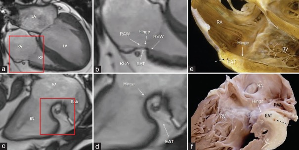
The right atrioventricular groove surrounds the anterior–lateral–inferior of the tricuspid hinge line. The so-called tricuspid annulus (TA) is almost a virtual structure in that a continuous and robust ring of connective tissue, from which tricuspid leaflets are suspended, does not exist at all. From an anatomical point of view, the TA may be divided in two components: the “mural annulus”, which lies on the right ventricle muscular crest around the atrioventricular groove and on which the anterior and posterior leaflets are suspended, and the “septal annulus”, which lies on the medial region of right atrioventricular orifice close to the central fibrous body and on which is inserted the septal leaflet. The mural annulus consists of the juxtaposition of four components: the atrial myocardium, the ventricular myocardium, the hinge line of the tricuspid leaflets, and the EAT filling the right atrioventricular groove. Notably, as in the posterior mitral annulus, the EAT penetrates deeply and extends up to the base of leaflets. The connective tissue of the fibrosa of leaflets tapers out in the adipose tissue of AV groove. With the exclusion of the small septal area, the EAT covers the entire C-shaped AV groove around the tricuspid valve orifice.[17] As for the left AV groove, this anatomical arrangement assures an excellent electrical insulation between the atrial and the ventricular myocardium [Figure 7].
Figure 7.
CMR SSFP still frame in four chamber view (a and b) and in right ventricular inflow (c and d) view. The areas in the red box in the panels a and c are magnified in panels b and d. (b) The image clearly shows the juxtaposition of the four components that form the tricuspid annulus. (d) The image shows how deeply the EAT penetrates into the atrioventricular groove. e and f are corresponding cuts through anatomic specimens to show the hinge of the tricuspid valve leaflet (white arrow) and the deep excursion of EAT into the right atrioventricular groove. RA = Right atrium, RV = Right ventricle, LA = Left atrium, LV = Left ventricle, RAA = Right atrial appendage, CMR SSFP = Cardiac magnetic resonance steady-state free precession, EAT = Epicardial adipose tissue
THE TRANSVERSE PERICARDIAL SINUS
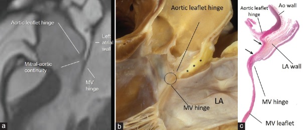
Usually from an imager's point of view the TPS is a virtual space between the aorta and the left and right atrial wall. However, in patients with abundant EAT, the adipose tissue invades deeply the TPS separating the aortic sinuses from the atrial walls. Notably in such a case, the EAT between noncoronary aortic sinus and atrial wall allows understanding the peculiar anatomic arrangement of the so-called mitral-aortic continuity. From the atrial perspective in this region, the atrial wall extends up to the hinge line of mitral valve. However, since the hinge line of anterior mitral leaflet lies lower than the hinge line of aortic leaflet, on the ventricular side, the space between the two hinge lines is occupied by a fibrous membrane more or less rectangular and delimited medially and laterally by the right and left fibrous trigones: the aortic-mitral fibrous continuity. More than the other imaging techniques, CMR provides conclusive images of this particular anatomic arrangement [Figure 8].
Figure 8.
(a) CMR SSFP still frame in long axis view showing in patient with abundant EAT as the adipose tissue separates the aortic wall from the atrial wall in the transverse pericardial sinus. Panel (b) shows anatomic specimen displayed in similar view showing EAT (asterisk) between the outside of the aortic sinus and the anterior wall of the LA. Aortic-mitral fibrous continuity is circled. Panel (c) is a histologic section in similar orientation to show fibrous tissue (stained red between the two arrows). The LA wall (stained brownish) is on the outside but there is no ventricular muscle in between aortic and mitral leaflets (see text). LA = Left atrium, CMR SSFP = Cardiac magnetic resonance steady-state free precession, EAT = Epicardial adipose tissue
CONCLUSIONS
This review described the pervasive nature of EAT. For this purpose, we use the balanced SSFP sequences of CMR. These sequences have the unique ability to distinguishing the adipose tissue from the blood and the muscle providing the clearest images of the EAT distribution ever. In general, the EAT is perceived as a layer of adipose tissue covering more or less extensively the surface of the heart. On the contrary, this tissue penetrates deeply into the heart filling any possible folding. We discovered as the EAT penetrate deeply into the interatrial groove separating the atrial walls, into the folding that forms the LLR, into the AVJ being one of the components of the annulus of both atrioventricular wall, and in the TPS clarifying the nature of the aortic-mitral fibrous continuity. However, a clear visualization of the EAT and its distribution inside the heart need the presence of abundant EAT. In general, in fact, these folding are almost virtual and cannot be visualized being below the spatial resolution of noninvasive imaging techniques. We strongly believe that noninvasive imaging techniques such as echocardiography, CT, and CMR should be used for illustrating normal anatomy in medical school and to young cardiologists as companion of anatomy from cadavers, and this review is an attempt to serve this purpose.
Financial support and sponsorship
Nil.
Conflicts of interest
There are no conflicts of interest.
REFERENCES
- 1.Iacobellis G, Corradi D, Sharma AM. Epicardial adipose tissue: Anatomic, biomolecular and clinical relationships with the heart. Nat Clin Pract Cardiovasc Med. 2005;2:536–43. doi: 10.1038/ncpcardio0319. [DOI] [PubMed] [Google Scholar]
- 2.Corradi D, Maestri R, Callegari S, Pastori P, Goldoni M, Luong TV, et al. The ventricular epicardial fat is related to the myocardial mass in normal, ischemic and hypertrophic hearts. Cardiovasc Pathol. 2004;13:313–6. doi: 10.1016/j.carpath.2004.08.005. [DOI] [PubMed] [Google Scholar]
- 3.Mazurek T, Zhang L, Zalewski A, Mannion JD, Diehl JT, Arafat H, et al. Human epicardial adipose tissue is a source of inflammatory mediators. Circulation. 2003;108:2460–6. doi: 10.1161/01.CIR.0000099542.57313.C5. [DOI] [PubMed] [Google Scholar]
- 4.Rabkin SW. Epicardial fat: Properties, function and relationship to obesity. Obes Rev. 2007;8:253–61. doi: 10.1111/j.1467-789X.2006.00293.x. [DOI] [PubMed] [Google Scholar]
- 5.Antonopoulos AS, Antoniades C. The role of epicardial adipose tissue in cardiac biology: Classic concepts and emerging roles. J Physiol. 2017;595:3907–17. doi: 10.1113/JP273049. [DOI] [PMC free article] [PubMed] [Google Scholar]
- 6.Iacobellis G, Assael F, Ribaudo MC, Zappaterreno A, Alessi G, Di Mario U, et al. Epicardial fat from echocardiography: A new method for visceral adipose tissue prediction. Obes Res. 2003;11:304–10. doi: 10.1038/oby.2003.45. [DOI] [PubMed] [Google Scholar]
- 7.Nakazato R, Shmilovich H, Tamarappoo BK, Cheng VY, Slomka PJ, Berman DS, et al. Interscan reproducibility of computer-aided epicardial and thoracic fat measurement from noncontrast cardiac CT. J Cardiovasc Comput Tomogr. 2011;5:172–9. doi: 10.1016/j.jcct.2011.03.009. [DOI] [PMC free article] [PubMed] [Google Scholar]
- 8.Gronemeyer SA, Steen RG, Kauffman WM, Reddick WE, Glass JO. Fast adipose tissue (FAT) assessment by MRI. Magn Reson Imaging. 2000;18:815–8. doi: 10.1016/s0730-725x(00)00168-5. [DOI] [PubMed] [Google Scholar]
- 9.Hanley PC, Tajik AJ, Hynes JK, Edwards WD, Reeder GS, Hagler DJ, et al. Diagnosis and classification of atrial septal aneurysm by two-dimensional echocardiography: Report of 80 consecutive cases. J Am Coll Cardiol. 1985;6:1370–82. doi: 10.1016/s0735-1097(85)80228-x. [DOI] [PubMed] [Google Scholar]
- 10.Laura DM, Donnino R, Kim EE, Benenstein R, Freedberg RS, Saric M. Lipomatous atrial septal hypertrophy: A Review of its anatomy, pathophysiology, multimodality imaging, and relevance to percutaneous interventions. J Am Soc Echocardiogr. 2016;29:717–23. doi: 10.1016/j.echo.2016.04.014. [DOI] [PubMed] [Google Scholar]
- 11.Anderson RH, Becker AE. Cardiac Anatomy. An Integrated Text and Colour Atlas. London: Gower Medical Publishing; 1980. [Google Scholar]
- 12.Dean JW, Ho SY, Rowland E, Mann J, Anderson RH. Clinical anatomy of the atrioventricular junctions. J Am Coll Cardiol. 1994;24:1725–31. doi: 10.1016/0735-1097(94)90179-1. [DOI] [PubMed] [Google Scholar]
- 13.Sánchez-Quintana D, Ho SY, Cabrera JA, Farré J, Anderson RH. Topographic anatomy of the inferior pyramidal space: Relevance to radiofrequency catheter ablation. J Cardiovasc Electrophysiol. 2001;12:210–7. doi: 10.1046/j.1540-8167.2001.00210.x. [DOI] [PubMed] [Google Scholar]
- 14.Cabrera JA, Ho SY, Climent V, Sánchez-Quintana D. The architecture of the left lateral atrial wall: A particular anatomic region with implications for ablation of atrial fibrillation. Eur Heart J. 2008;29:356–62. doi: 10.1093/eurheartj/ehm606. [DOI] [PubMed] [Google Scholar]
- 15.Agostini F, Click RL. More than just the:” “Q-tip sign”. J Am Soc Echocardiogr. 2001;14:832–3. doi: 10.1067/mje.2001.110373. [DOI] [PubMed] [Google Scholar]
- 16.Ho SY. Anatomy of the mitral valve. Heart. 2002;88(Suppl 4):iv5–10. doi: 10.1136/heart.88.suppl_4.iv5. [DOI] [PMC free article] [PubMed] [Google Scholar]
- 17.Faletra FF, Leo LA, Paiocchi VL, Schlossbauer SA, Borruso MG, Pedrazzini G, et al. Imaging-based tricuspid valve anatomy by computed tomography, magnetic resonance imaging, two and three-dimensional echocardiography: Correlation with anatomic specimen. Eur Heart J Cardiovasc Imaging. 2019;20:1–3. doi: 10.1093/ehjci/jey136. [DOI] [PubMed] [Google Scholar]


