Abstract
Controllable, precise, and stable rotational manipulation of model organisms is valuable in many biomedical, bioengineering, and biophysics applications. We present an acoustofluidic chip capable of rotating Caenorhabditis elegans (C. elegans) in both static and continuous flow in a controllable manner. Rotational manipulation was achieved by exposing C. elegans to a surface acoustic wave (SAW) field that generated a vortex distribution inside a microchannel. By selectively activating interdigital transducers, we achieved bidirectional rotation of C. elegans, namely counterclockwise and clockwise, with on-demand switching of rotation direction in a single chip. In addition to continuous rotation, we also rotated C. elegans in a stepwise fashion with a step angle as small as 4° by pulsing the signal duration of SAW from a continuous signal to a pulsed signal down to 1.5 ms. Using this device, we have clearly imaged the dopaminergic neurons of C. elegans with pdat-1:GFP expression, as well as the vulval muscles and muscle fibers of the worm with myo-3::GFP fusion protein expression in different orientations and three dimensions. These achievements are difficult to realize through conventional (i.e., non-confocal) microscopy. The SAW manipulations did not detectably affect the health of the model organisms. With its precision, controllability, and simplicity in fabrication and operation, our acoustofluidic devices will be well-suited for model organism studies.
Introduction
Caenorhabditis elegans (C. elegans), because of its relatively simple and well-characterized morphology and neuronal structure,1,2 has long been employed as a model organism in developmental biology and neuroscience.3,4 Most importantly, it has not only organs and tissues that are highly similar to those of humans, but also a completely sequenced and well-annotated genome that is relatively homologous to humans.5,6 Therefore, studying differences in sensory and other behaviors and morphologies of C. elegans with distinct genetic model systems under given conditions has benefited the studies of human diseases and the elucidation of genetic and cellular mechanisms.1,2,7–10 Precise, controllable rotational manipulation of C. elegans can be a powerful tool to efficiently, rapidly, and three-dimensionally interrogate cell morphologies, tissue structure, and organs at desired orientations.2,5,8,9,11–20
Despite their importance, approaches that can rotate small model animals such as C. elegans are limited, including the implementation of stepper motors21,22 and tailored channel geometries20,23 in a microchannel. The stepper motor approach allows for rapid, highly controllable orientation from any angle, yet it is expensive and cumbersome. Using specially designed microchannels to rotate small model animals is relatively simple, but it lacks accuracy and precision.23 To tackle these issues, we have previously reported on-chip rotational manipulation devices to rotate microparticles, cells, and C. elegans using oscillating microbubbles16 or micro-solid-structures driven by bulk acoustic waves (BAW).11,24,25 These BAW-based devices have some limitations. For example, model animals can be rotationally manipulated only at the specific location, in a static flow, or in one orientation (either clockwise or counterclockwise). As a result, it is essential to develop a method that can rotate small model animals in both static and continuous flow at any location in the channel, with on-demand switching of rotational orientation.
Due to its high biocompatibility, fast fluidic actuation, contact-free manipulation and convenient on-chip integration, the surface acoustic wave (SAW) has recently proved itself a promising tool for a wide range of microfluidic applications.26–34Here, we present a SAW-based device that can rotate C. elegans in a precise, controllable manner, which is based on the acoustic streaming induced by travelling surface acoustic waves. By altering the structure of acoustic streaming through the modulation of SAW, we can rotate C. elegans in two different directions (i.e., clockwise and counterclockwise) in a continuous or stepwise fashion, achieving dynamic control over the orientation of C. elegans. With our SAW device, most importantly, C. elegans can be rotated in continuous flow as well as in static flow, which can potentially improve imaging speed. Compared to existing methods, our approach is highly biocompatible, stable, easy to control, convenient for integrating with other microfluidic components. With these attributes, our device may be developed into a multifunctional platform for the analysis of small model animals, such as 3D imaging-based C. elegans sorting and screening.
Device design and concept
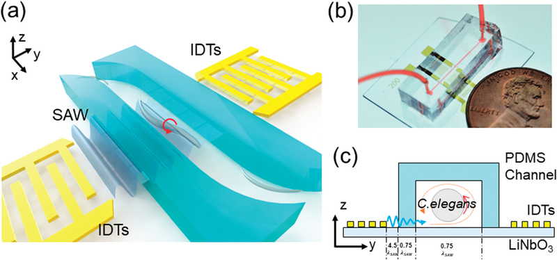
A schematic of our design and working concept is shown in Fig. 1a. The device consists of a single-layer polydimethylsiloxane (PDMS) microfluidic channel featuring one inlet and one outlet, respectively, for loading and unloading C. elegans samples, and a pair of interdigital transducers (IDTs) deposited on a lithium niobate (LiNbO3) substrate. An image of this device is in Fig. 1b. When the IDT on one side is excited by a radio frequency (RF) signal, a traveling SAW is generated and then travels along the y direction. The traveling SAW then propagates into the PDMS microchannel and induces acoustic streaming inside. The induced acoustic streaming in turn develops a vortex inside the PDMS microchannel that can be used to rotate C. elegans in a certain direction. As shown in Fig. 1c, a traveling SAW generated by the left IDT travels rightward and propagates into the channel. This results in a counterclockwise vortex (orange circle) that can rotate C. elegans in the counterclockwise direction out-of-plane (i.e., in the plane parallel to the propagation direction). Conversely, when the right IDT is excited, we can rotate C. elegans in the clockwise direction.
Fig. 1.
Design and working concept of the SAW-based C. elegans rotation device. (a) Schematic and (b) photograph of the device. (c) Working principle of the SAW-based rotation device in y-z side view. Here the λSAW is 200 μm. The SAW generated from the activated left IDT travels into the microchannel and induces acoustic streaming, which can rotate C. elegans along the streaming direction.
Materials and methods
Device fabrication
Our SAW device mainly consists of two components: a PDMS channel and a LiNbO3 substrate patterned with one pair of IDTs. The PDMS microchannel, of height of 120 μm and width of 150 μm, was fabricated by photolithography and PDMS replica molding. The width of the PDMS walls was 150 μm. First, an SU-8 master mold was prepared by standard photolithography, where a silicon wafer was spin-coated with a 120 μm-thick layer of SU-8 100 photoresist (MicroChem, USA) and then patterned by optical lithography. Then, a silane vapor (1H,1H,2H,2H-perfluorooctyl-trichlorosilane, Sigma-Aldrich, USA) was used to modify the surface of the mold for one hour. After silane coating, a mixture of PDMS base and cross-linker (Sylgard 184, Dow Corning, USA) at a ratio of 10:1 (w/w) was poured onto the master mold and then cured at 65 °C for an hour to form the microchannel. Once cured, the microchannel was punched at predesignated positions to open an inlet and an outlet for sample loading and unloading, respectively. The LiNbO3 substrate was fabricated by standard photolithography, e-beam evaporation, and lift-off processes. To fabricate the LiNbO3 substrate with IDTs, we first coated a Y + 128° X-propagation LiNbO3 wafer with a layer of SPR3012 photoresist (MicroChem, USA), followed by optical lithography and chemical developing. Then, titanium and gold layers (Ti/Au, 10/90 nm) were deposited on the LiNbO3 substrate by e-beam evaporation, followed by the lift-off process to form one pair of IDTs. Both of the IDTs had 20 pairs of electrode. The spacing between each electrode was 50 μm and the aperture was 2 mm. The distance between two IDTs was 2.25 mm. Once both the PDMS channel and LiNbO3 substrate were prepared, they were treated with oxygen plasma and then bonded together, followed by incubation at 65 °C overnight.
Preparation of C. elegans
Nematode growth medium agar (K-agar)35 was prepared by first dissolving 2.36 g of KCl, 3 g of NaCl, 2.5 g of peptone, and 20 g agar in 1 L of distilled water, followed by autoclaving the mixture. Once the autoclaved mixture was cooled down to 55 °C, it was mixed with 1 mL 1 M CaCl2, 1 mL 1 M MgSO4, 1 mL 10 mg mL−1 cholesterol, and 5 mL 1.25 mg mL−1 nystatin to obtain the final K-agar. The K-agar was then poured on a Petri dish and seeded with bacteria within 24 hours. K-medium buffer for C. elegans was made by adding 2.36 g of KCl and 3 g of NaCl into 1 L of distilled water and autoclaving the mixture.
Both wild-type and transgenic C. elegans were tested in our devices. The N2 Bristol wild-type strain, SJ4005 [zcls4; hsp-4p::GFP], and RW1596 [myo-3(st386); stEx30 [myo-3p:GFP: myo-3 + rol-6 (su1006)]] strains were obtained from the Caenorhabditis Genetics Center. The BY200 strain [vtls1; dat- 1p:GFP] was kindly provided by Michael Aschner (Albert Einstein College of Medicine, Bronx, NY). Nematodes were maintained on K-agar plates at 20 °C. Semi-synchronous populations of adult nematodes were obtained by first washing a population of day 2–3 adults with their larvae from the plate into a 15 mL conical tube using sterile K-medium. Afterwards, the worms were washed 3 times with 10 mL sterile K-medium, followed by gravity settling the adults and aspirating the supernatant to remove bacteria and larvae. Before being loaded into the channel, nematodes were all paralyzed with sodium azide at a final concentration of 10 mM.
Device operation
Every experiment was conducted on a microscope (TE2000-U, Nikon, Japan). Individual C. elegans were stably injected into the microchannel through 1 mL syringes (BD Bioscience, USA) administered by an automated syringe pump (neMESYS, Germany). A function generator (AFG3011C, Tektronix, USA) and an amplifier (25A250A, Amplifier Research, USA) were used to drive the IDTs. The resonant frequency of the device was first identified using a network analyzer (Vector Network Analyzer 2180, Array Solutions, USA). Upon identifying the resonant frequency, we then compared the acoustic streaming intensity in the microchannel within a frequency range (±1 MHz) around the resonant frequency at the same amplitude. An optimal driving frequency of 19.32 MHz was chosen because at this frequency the IDTs generated the strongest acoustic streaming in the microchannel. Images and videos were captured by a fast camera (Fastcam SA4, Photron, USA) through Photron FASTCAM Viewer (PFV, Photron, USA). A Nikon filter cube (excitation: 470 nm; emission: 515 nm), a CCD digital camera (CoolSNAP HQ2, Photometrics, USA), and a fiber optic illumination system (Intensilight, Nikon, Japan) were used to record the fluorescent images and videos. All acquired images and videos were analyzed by ImageJ (NIH, USA).
Results and discussion
Acoustic field in the microchannel
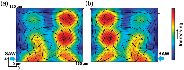
We first numerically calculated the acoustic pressure and acoustic streaming patterns induced by the SAW field on the y-z plane of the PDMS channel. To do so, we applied the perturbation theory36 to the mass and momentum conservation equations, deducing the first-order equations which govern the acoustic field and the second-order equations which govern the acoustic streaming patterns. COMSOL (Multiphysics 5.3, COMSOL Inc.) was used to solve the governing equations. The details of the numerical approach were reported in our previous work.33 Numerical results of the absolute acoustic pressure and acoustic streaming patterns in the y-z cross section of the PDMS channel activated by SAW coming from the left and right IDTs are shown in Fig. 2a and b, respectively. The simulation results show that when the SAW is from the left IDT, the generated acoustic streaming develops a large, counterclockwise vortex in the middle of the channel (Fig. 2a), while when the SAW is from the right IDT, a clockwise vortex is developed (Fig. 2b). In addition, some small vortices were generated at the corners of the channel for both cases. Nevertheless, because the adult C. elegans is around 40 μm in diameter, only the large vortex can potentially rotate them. Moreover, the simulation results indicate that when the SAW is from either of the IDTs, a pressure node is formed near the middle of the channel, which can attract the worm due to its acoustic properties. Most importantly, these results imply that when the SAW comes from either of the IDTs, the worm would be first dragged to the pressure node near the middle of the channel and then rotated by the large vortex.
Fig. 2.
Simulated acoustic streaming patterns and the distribution of acoustic pressure in the microchannel when the SAW is from either of the IDTs. Red and blue colors indicate high and low magnitudes of acoustic pressure, respectively. The direction of acoustic streaming lines is indicated by the black arrows. (a) The SAW coming from the left side generates a large, counterclockwise vortex in the middle of the channel and some smaller vortices near the edges, whereas (b) the SAW coming from the right side generates a clockwise vortex in the middle of the channel and also some smaller vortices. Moreover, the SAW coming from either side forms a pressure node near the middle of the channel.
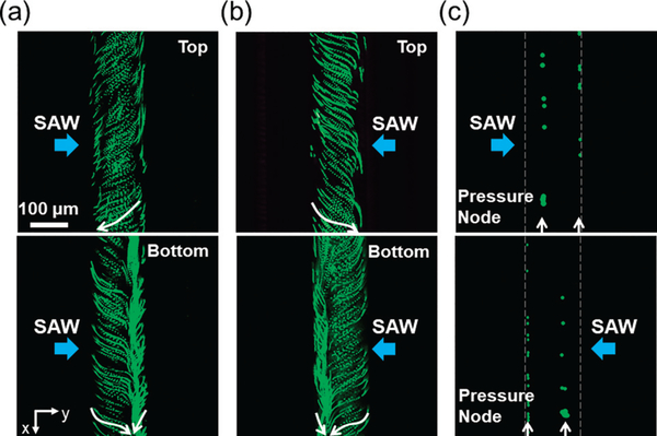
To visualize the acoustic streaming induced by SAW in the microchannel and verify the simulation results, we introduced diluted, 1 μm fluorescent polystyrene microparticles into the microchannel and traced their movement. As shown in Fig. 3a and b, when an RF signal (12.6 Vpp) was applied to the IDT on either side, one large and one small vortex were observed inside the microchannel. When the SAW came from the left IDT in y direction, 1 μm microparticles moved from right to left in the top plane of the microchannel (Fig. 3a, top), while in the bottom plane, 1 μm particles mostly moved from left to right (Fig. 3a, bottom). These phenomena thus induced a large, counterclockwise vortex in the microchannel, which agreed with the simulation results shown in Fig. 2a. By contrast, when the SAW was from the right IDT, the direction of the large vortex was reversed (Fig. 3b), namely clockwise, which also confirmed the simulation results shown in Fig. 2b. These results clearly display the structures of the vortex induced by the acoustic streaming patterns generated by the SAW coming from either of the IDTs.
Fig. 3.
Fluorescent images showing the acoustic streaming pattern and the distribution of acoustic pressure in the microchannel, when the IDT on one side is activated. Green fluorescence tracing of 1 μm particles in top and bottom planes of the microchannel when SAW came from (a) the left IDT and (b) the right IDT, which displays the streaming inside the microchannel. White arrows show the moving direction of particles. (c) Green fluorescence distribution of 10 μm particles when SAW came from the left or right IDTs, which shows the positions of pressure node inside the microchannel, as pointed by white arrows.
Other than acoustic streaming, the distribution of acoustic pressure in the microchannel is also an important phenomenon that needs to be taken into account. Typically, acoustic radiation force dominates the motion of relatively big microparticles, and can move big particles and adult C. elegans towards pressure nodes formed in microchannels.32 To observe this phenomenon in our device, we injected 10 μm fluorescent polystyrene particles into the microchannel. Upon applying an RF signal (12.6 Vpp) only to the left IDT, 10 μm particles moved towards two lines corresponding to two pressure nodes formed in the microchannel (Fig. 3c, top). One pres-sure node was slightly leftward from the middle, while the other was near the right sidewall of the microchannel. Applying the same RF signal to the right IDT alone, the positions of the two pressure nodes were then shifted, which were completely opposite to those formed when only the left IDT was activated (Fig. 3c, bottom). These results suggest that with either one of the IDTs activated, two pressure nodes were established in the microchannel, and the distance between them remained unchanged (~100 μm).
Bi-directional rotation of C. elegans
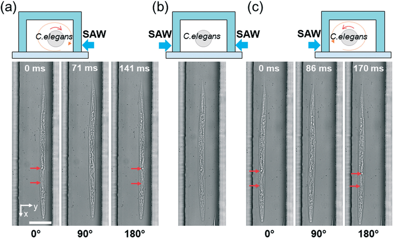
To demonstrate the rotational manipulation of C. elegans with our SAW device, we selected adult, wild-type C. elegans as the target to be manipulated. As shown in Fig. 4a, when an RF signal (25.6 VPP) was applied to the right IDT, the C. elegans was first dragged and trapped to the pressure node line by the acoustic radiation force induced by SAW. Then the vortex induced by the acoustic streaming shown in Fig. 3b continuously rotated this animal along the pressure node line; the direction of this rotation was the same as the vortex direction. Once the left IDT was also activated with the same RF signal (i.e., the two IDTs were activated simultaneously), two traveling SAWs propagating toward each other were generated, thereby establishing a one-dimensional standing SAW field. This standing SAW field then formed a pressure node in the middle of the channel, whereby the C. elegans could be focused and remained stationary, as shown in Fig. 4b. Upon deactivating the right IDT (i.e., only the left IDT was activated), the worm was then shifted transversely to the left pressure node line and then continuously rotated in the corresponding vortex direction (Fig. 4c), which was different from the rotation direction in Fig. 4a. The entire process showing the motion of C. elegans due to the selective activation of the IDTs is in Video S1.† These results demonstrate that by selectively activating the IDTs, we could rotate the C. elegans in opposite directions, as well as focusing the C. elegans in the middle of the microchannel. Moreover, the results also suggest that we could rotate C. elegans along its long axis, which would allow us to conveniently investigate C. elegans from different angles without changing the focal plane of microscope.
Fig. 4.
Rotating C. elegans in opposite directions using SAW. (a) Schematic and image sequences showing that the C. elegans is continuously rotated clockwise when only the right IDT is activated. (b) Schematic and images showing that the C. elegans is focused in the middle of the channel when both of the IDTs are activated. (c) Schematic and images sequences showing that the C. elegans is continuously rotated counterclockwise when only the left IDT is activated. Scale bars: 100 μm. Red arrows point out differences among figures, demonstrating rotation.
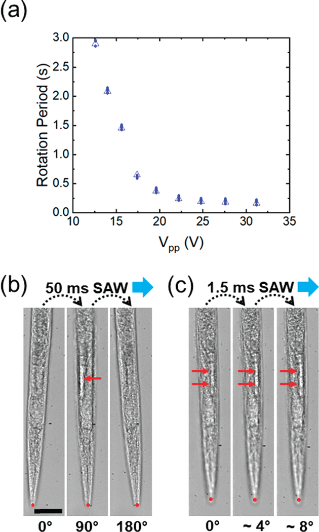
Having demonstrated the bi-directional rotation of C. elegans with our device, we then characterized the rotation period of C. elegans, which was directly related to the power (VPP) of RF signals applied (Fig. 5a). When the power was 12.6 VPP, our device rotated the C. elegans at a rotation period of 3 seconds, and as the power increased to 31.2 VPP, the rotation period was reduced to ~160 ms. Overall, the rotation period dramatically reduced as the power was increased within the power range of 12.6−25 VPP; however, from 25−31.2 VPP, the rotation period changed insignificantly. The reason may be that the drag force applied to the worm increased significantly when the acoustic streaming velocity was increased due to the raised power. Since the drag force is quadratically proportional to the velocity, it increases much faster when velocity increases. As a result, when a high power is applied, the drastically increased drag force balanced against the acoustic streaming force. The power range we tested was safe for adult C. elegans, since we did not observe any change in worm appearance or behavior when SAW was applied. Furthermore, we investigated the influence from paralysis and SAW treatment on the worms’ movement ability and reproduction ability with a controlled experiment. The results showed that more than 99.2% of the worms could resume their activities in all groups after 30 minutes. Also, we did not observe any significant difference in the number of offspring between any of the four groups after a one-way ANOVA test (Fig. S1 in the ESI†). These results suggest that by adjusting the power of the applied RF signals (Vpp), we could rotate C. elegans at different speed and that the SAW we applied does not reduce the viability and activity of the C. elegans.
Fig. 5.
(a) Plot of the rotation period of one C. elegans versus the driving voltage applied to the left IDT. The plot suggests that we can rotate C. elegans in a large speed range with our SAW device. Image sequences showing the stepwise rotation of C. elegans when the IDT was supplied with pulsed signals of (b) 50 ms duration and (c) 1.5 ms duration. Red dots label the position of worm’s tip to show there is no drifting. Red arrows point out the differences among figures, which result from rotation. Scale bar: 50 μm.
In addition to continuous rotation, we also achieved stepwise rotation by adjusting the duration of the applied RF signal. For example, a short pulse with a duration of 50 ms allowed for rotating an individual C. elegans by ~90°; upon applying two pulses of 50 ms duration, the C. elegans could be rotated by 180° in two steps, as shown in Fig. 5b. Further reducing the duration of a single pulse down to only 1.5 ms, we could rotate the same C. elegans by around 4° in one step, as shown in Fig. 5c and Video S2.† In these experiments, no drifting was observed during rotations, as can be seen from the position of the worm’s tip (marked by red dots in Fig. 5b and c). In addition, the worm stopped moving immediately upon turning off the RF signal, proving that this stepwise manipulation is highly stable and controllable. With the ability to rotate C. elegans in a controllable, stepwise fashion, interrogating C. elegans at any desired angle should be possible.
Rotating multiple C. elegans simultaneously
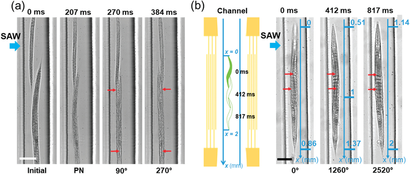
Rotating multiple C. elegans simultaneously may enable higher-throughput 3D imaging of C. elegans. To demonstrate the capability of our device for high-throughput, rotational manipulation, we first rotated two C. elegans simultaneously in the channel, wherein one adult C. elegans and one L4 (fourth larval) stage C. elegans were used and aligned in series. When the left IDT was excited (31.2 VPP), the two C. elegans were first trapped along the same pressure node in ~207 ms because of the generated acoustic radiation force, and then started rotating at the same direction (Fig. 6a and Video S3†). Note, however, that the two worms behaved differently in terms of their rotation speed; under this acoustic field, the adult and L4 C. elegans were rotated at average rotation speeds of ~377 and 706 rpm, respectively. This difference may come from the size difference between two worms.
Fig. 6.
Higher-throughput rotation and 3D imaging of C. elegans via SAW. (a) Image sequence displaying the trapping and rotation of multiple worms in series arrangement, where the SAW comes from left IDT. PN denotes the pressure node. Note that the rotation angles indicated are only for the big worm. Red arrows point out the difference between figures. (b) Schematic and images showing the rotation of C. elegans in a continuous flow, where the SAW comes from the left IDT. Left image: the whole worm entered into the area of IDTs’ aperture. Point “x = 0” is the entry point of this area. Middle image: after rotating 3.5 circles, the worm approaches the midpoint of the aperture area (x = 1). Right image: after rotating another 3.5 circles, the worm exited the aperture area. Point “x = 2” is the ending point of this area. The average speed of the worm moving along x direction was 1.59 mm s−1. Red arrows point out the difference between figures. Scale bar: 100 μm.
When exposed to the same streaming field, the larger worm, due to its larger size, was subject to a drag force larger than that experienced by the smaller worm; thus, its rotation speed was less than the small worm. Despite the variation in the rotation speed, our device’s ability to rotate two worms arranged in series reveals its potential for higher-throughput rotation.
In addition to rotating two C. elegans in series arrangement in a static flow, we also rotated C. elegans in a continuous flow regime to demonstrate our device’s potential for higher-throughput rotation and imaging (i.e., continuous entry and exit of sequential worms with rotation of each). Generally, the aperture of IDTs determines the width of SAWworking region; in our device, the IDTs’ aperture was 2 mm, therefore rendering the SAW-working region 2 mm long along the length of the channel. Under a continuous flow (the flow rate was equal to 5 μL min−1) and a SAW field (31.2 VPP), one adult worm could be continuously rotated at an average rotation period of 117 ms, as it traveled through the SAW-working region at an average speed of 1.59 mm s−1 (Fig. 6b). The worm first entered into the aperture area (Fig. 6b- left image), then proceeded to the midpoint of this area after rotating approximately 3.5 circles (Fig. 6b-middle image), and finally began to leave this area after rotating approximately another 3.5 circles (Fig. 6b-right image). The dynamic process can be seen in Video S4.† This result suggests that in our device, we could rotate C. elegans at any location within the SAW-working region, as opposed to at a specific location. Most importantly, this result confirms that we can rotate one C. elegans (potentially multiple C. elegans in series arrangement) as it is traveling through the channel, and it demonstrates the potential of our chip for high-throughput imaging by rotating C. elegans in a continuous flow. Furthermore, because of its simplicity in device configuration, our device may be integrated with existing techniques such as acoustofluidic pumping37 and cellphone-based imaging38 to develop a monolithic, self-contained system for high-throughput 3D imaging of C. elegans.
Imaging of C. elegans with the SAW device
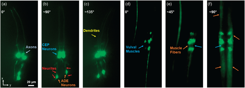
To demonstrate our device’s ability to perform 3D imaging of model organisms such as C. elegans, we first used it to examine the neurons of the C. elegans strain expressing the vtIs1 (pdat-1:GFP) transgene, which is expressed in the strain BY200 and produces bright green fluorescence only in the 8 dopaminergic neurons. Conventionally, examining these individual neurons is difficult without using confocal microscopy. After controllably rotating to any angle using our chip, we obtained fluorescent results from distinct orientations of the worm. In Fig. 7a–c, a L4-stage worm was continuously rotated to get the fluorescent images of the neurons. Because of the fluorescence overlapping, only two of all four CEP neurons could be seen as in Fig. 7a. However, the axons between CEP neurons were clearly displayed in this orientation. After rotating about 90°, all four CEP neurons were imaged in Fig. 7b. The positions of two ADE neurons and distribution of neurites around ADE neurons were determined by combining Fig. 7a and b. Furthermore, only two dendrites are shown in Fig. 7a and b. We kept rotating the worm by about 135°; all four dendrites are displayed in Fig. 7c. By quickly and accurately rotating the worms to different orientations, we clearly present biological characteristics of the worms. In addition to the worm neuron imaging, we used the device to examine the muscles of the C. elegans strain RW1596 expressing the myo-3::GFP fusion protein, which makes up muscle fibers in body walls and vulval muscles. The results are shown in Fig. 7d–f. Before rotation of the worm, vulval muscles are shown from the side as in Fig. 7d. It was difficult to observe all the muscles. After rotating about 45°, the four vulval muscles could be distinguished; some muscle fibers are shown as in Fig. 7e. We kept rotating the worm by about 90°; all the vulval muscles were clearly imaged from the front, and many more muscle fibers were observed as in Fig. 7f. These two imaging examples clearly display the controllable imaging ability of our SAW devices. This ability will be highly advantageous when imaging structures such as muscle mitochondria, which to date requires a rol genetic background for optimal visualization of the body wall.39
Fig. 7.
Examination of the neurons and muscles of the C. elegans from different orientations using our SAW device. (a) Fluorescent image showing the axons between CEP neurons of a L4 stage nematode expressing GFP under the control of the dat-1 promoter [strain BY200, genotype vtls1 (pdat-1:GFP; rol-6)]. (b) After rotating about 90°, all four CEP neurons and neurites around two ADE neurons were clearly displayed in the fluorescent image. (c) After rotating to about 135°, all four dendrites were clearly displayed in the fluorescent image. (d) Fluorescent image showing the side view of the vulval muscles of an adult myo-3::GFP worm [strain RW1596, genotype myo-3(st386); stEx30 (myo-3p::GFP::myo-3 + rol-6(su1006))]. (e) After rotating about 45°, all four vulval muscles and some muscle fibers were displayed in the fluorescent image. (f) After rotating to about 90°, all four vulval muscles were shown in the front view, and the muscle fibers were distinguished in the fluorescent image.
Conclusions
In summary, we have developed a SAW-based method for precise and controllable rotational manipulation of C. elegans. Our method can rotate C. elegans continuously in two directions (clockwise and counterclockwise) with a controllable speed. Using short RF pulses to achieve dynamic position control, the angle of the rotation can be adjusted down to ~4°. Moreover, not only can our device simultaneously rotate two worms aligned along the same pressure node line at different speeds in a static flow, but it can also rotate C. elegans in a continuous flow, which makes it suitable for high-throughput applications. Using this method, we have successfully imaged neurons, vulval muscles, and muscle fibers of the worms from different, though only specific, orientations. Our device is easy to fabricate and operate, and can be conveniently integrated with other on-chip units such as microfluidic sorting devices to develop all-in-one, multifunctional platforms for model organism studies.
Supplementary Material
Acknowledgements
This research was supported by National Institutes of Health (R43 OD024963, P42 ES010356 and F32 ES027306) and National Science Foundation (ECCS-1807601). J. Z. thanks the China Scholarship Council (CSC) for the financial support.
Footnotes
Conflicts of interest
T. J. H. has four US patents (patent numbers: 8573060; 9608547; 9606086; and 9757699) related to SAW, acoustofluidics, and acoustic tweezers. He has also cofounded a start-up company, Ascent Bio-Nano Technologies Inc., to commercialize technologies involving SAW, acoustofluidics, and acoustic tweezers.
Electronic supplementary information (ESI) available: Video 1: bidirectional rotation of C. elegans with on-demand switching of rotation direction. Video 2: stepwise rotation of C. elegans with a step angle as small as 4°. Video 3: rotating two C. elegans in series arrangement simultaneously. Video 4: rotation of C. elegans in continuous flow. See DOI: 10.1039/c8lc01012a
References
- 1.Cho Y, Porto DA, Hwang H, Grundy LJ, Schafer WR and Lu H, Lab Chip, 2017, 17, 2609–2618. [DOI] [PMC free article] [PubMed] [Google Scholar]
- 2.Rouse T, Aubry G, Cho Y, Zimmer M and Lu H, Lab Chip, 2017, 18, 505–513. [DOI] [PMC free article] [PubMed] [Google Scholar]
- 3.Gokce SK, Guo SX, Ghorashian N, Everett WN, Jarrell T, Kottek A, Bovik AC and Ben-Yakar A, PLoS One, 2014, 9, e113917. [DOI] [PMC free article] [PubMed] [Google Scholar]
- 4.Guo SX, Bourgeois F, Chokshi T, Durr NJ, Hilliard MA, Chronis N and Ben-Yakar A, Nat. Methods, 2008, 5, 531–533. [DOI] [PMC free article] [PubMed] [Google Scholar]
- 5.Ardeshiri R, Mulcahy B, Zhen M and Rezai P, Biomicrofluidics, 2016, 10, 064111. [DOI] [PMC free article] [PubMed] [Google Scholar]
- 6.Dong L, Cornaglia M, Lehnert T and Gijs MAM, Lab Chip, 2016, 16, 574–585. [DOI] [PubMed] [Google Scholar]
- 7.Chung K, Crane MM and Lu H, Nat. Methods, 2008, 5, 637–643. [DOI] [PubMed] [Google Scholar]
- 8.Ben-Yakar A, Chronis N and Lu H, Curr. Opin. Neurobiol, 2009, 19, 561–567. [DOI] [PMC free article] [PubMed] [Google Scholar]
- 9.Aubry G and Lu H, Lab Chip, 2017, 4303–4311. [DOI] [PubMed] [Google Scholar]
- 10.Mondal S, Hegarty E, Martin C, Gokce SK, Ghorashian N and Ben-Yakar A, Nat. Commun, 2016, 7, 1023. [DOI] [PMC free article] [PubMed] [Google Scholar]
- 11.Ozcelik A, Nama N, Huang PH, Kaynak M, McReynolds MR, Hanna-Rose W and Huang TJ, Small, 2016, 12, 5120–5125. [DOI] [PMC free article] [PubMed] [Google Scholar]
- 12.Bakhtina NA and Korvink JG, RSC Adv, 2014, 4, 4691–4709. [Google Scholar]
- 13.Tsutsui H, Valamehr B, Hindoyan A, Qiao R, Ding X, Guo S, Witte ON, Liu X, Ho CM and Wu H, Nat. Commun, 2011, 2, 167. [DOI] [PMC free article] [PubMed] [Google Scholar]
- 14.Tung YC, Hsiao AY, Allen SG, Torisawa YS, Ho M and Takayama S, Analyst, 2011, 136, 473–478. [DOI] [PMC free article] [PubMed] [Google Scholar]
- 15.Hou HW, Bhagat AAS, Lin Chong AG, Mao P, Wei Tan KS, Han J and Lim CT, Lab Chip, 2010, 10, 2605. [DOI] [PubMed] [Google Scholar]
- 16.Ahmed D, Ozcelik A, Bojanala N, Nama N, Upadhyay A, Chen Y, Hanna-Rose W and Huang TJ, Nat. Commun, 2016, 7, 11085. [DOI] [PMC free article] [PubMed] [Google Scholar]
- 17.Crane MM, Stirman JN, Ou CY, Kurshan PT, Rehg JM, Shen K and Lu H, Nat. Methods, 2012, 9, 977–980. [DOI] [PMC free article] [PubMed] [Google Scholar]
- 18.Streets AM and Huang Y, Biomicrofluidics, 2013, 7, 011302. [DOI] [PMC free article] [PubMed] [Google Scholar]
- 19.Goodman MB, Lindsay TH, Lockery SR and Richmond JE, Electrophysiological Methods for Caenorhabditis elegans Neurobiology, Elsevier Inc., 2nd edn, 2012, vol. 107. [DOI] [PMC free article] [PubMed] [Google Scholar]
- 20.Rohde CB, Zeng F, Gonzalez-Rubio R, Angel M and Yanik MF, Proc. Natl. Acad. Sci. U. S. A, 2007, 104, 13891–13895. [DOI] [PMC free article] [PubMed] [Google Scholar]
- 21.Pardo-Martin C, Chang TY, Koo BK, Gilleland CL, Wasserman SC and Yanik MF, Nat. Methods, 2010, 7, 634–636. [DOI] [PMC free article] [PubMed] [Google Scholar]
- 22.Pardo-Martin C, Allalou A, Medina J, Eimon PM, Wahlby C and Yanik MF, Nat. Commun, 2013, 4, 1467. [DOI] [PMC free article] [PubMed] [Google Scholar]
- 23.de I Caceres C, Valmas N, Hilliard MA and Lu H, PLoS One, 2012, 7, e35037. [DOI] [PMC free article] [PubMed] [Google Scholar]
- 24.Huang PH, Xie Y, Ahmed D, Rufo J, Nama N, Chen Y, Chan CY and Huang TJ, Lab Chip, 2013, 13, 3847–3852. [DOI] [PMC free article] [PubMed] [Google Scholar]
- 25.Nama N, Huang PH, Huang TJ and Costanzo F, Lab Chip, 2014, 14, 2824–2836. [DOI] [PMC free article] [PubMed] [Google Scholar]
- 26.Ozcelik A, Rufo J, Guo F, Gu Y, Li P, Lata J and Huang TJ, Nat. Methods, 2018, 15, 1021–1028. [DOI] [PMC free article] [PubMed] [Google Scholar]
- 27.Zhang SP, Lata J, Chen C, Mai J, Guo F, Tian Z, Ren L, Mao Z, Huang P, Li P, Yang S and Huang TJ, Nat. Commun, 2018, 9, 2928. [DOI] [PMC free article] [PubMed] [Google Scholar]
- 28.Wu M, Ouyang Y, Wang Z, Zhang R, Huang P-H, Chen C, Li H, Li P, Quinn D, Dao M, Suresh S, Sadovsky Y and Huang TJ, Proc. Natl. Acad. Sci. U. S. A, 2017, 114, 10584–10589. [DOI] [PMC free article] [PubMed] [Google Scholar]
- 29.Li P and Huang TJ, Anal. Chem, 2019, 91, 757–767. [DOI] [PMC free article] [PubMed] [Google Scholar]
- 30.Collins DJ, Alan T, Helmerson K and Neild A, Lab Chip, 2013, 13, 3225–3231. [DOI] [PubMed] [Google Scholar]
- 31.Ding X, Lin S-CS, Kiraly B, Yue H, Li S, Chiang I-K, Shi J, Benkovic SJ and Huang TJ, Proc. Natl. Acad. Sci. U. S. A, 2012, 109, 11105–11109. [DOI] [PMC free article] [PubMed] [Google Scholar]
- 32.Ding X, Li P, Lin S-CS, Stratton ZS, Nama N, Guo F, Slotcavage D, Mao X, Shi J, Costanzo F and Huang TJ, Lab Chip, 2013, 13, 3626–3649. [DOI] [PMC free article] [PubMed] [Google Scholar]
- 33.Guo F, Mao Z, Chen Y, Xie Z, Lata JP, Li P, Ren L, Liu J, Yang J, Dao M, Suresh S and Huang TJ, Proc. Natl. Acad. Sci. U. S. A, 2016, 113, 1522–1527. [DOI] [PMC free article] [PubMed] [Google Scholar]
- 34.Mao Z, Li P, Wu M, Bachman H, Mesyngier N, Guo X, Liu S, Costanzo F and Huang TJ, ACS Nano, 2017, 11, 603–612. [DOI] [PMC free article] [PubMed] [Google Scholar]
- 35.Boyd WA, Smith MV and Freedman JH, in Developmental Toxicology: Methods and Protocols, ed. Harris C and Hansen JM, Humana Press, Totowa, NJ, 2012, pp. 15–24. [Google Scholar]
- 36.Muller PB, Barnkob R, Jensen MJH and Bruus H, Lab Chip, 2012, 12, 4617–4627. [DOI] [PubMed] [Google Scholar]
- 37.Huang PH, Nama N, Mao Z, Li P, Rufo J, Chen Y, Xie Y, Wei CH, Wang L and Huang TJ, Lab Chip, 2014, 14, 4319–4323. [DOI] [PMC free article] [PubMed] [Google Scholar]
- 38.Bachman H, Huang PH, Zhao S, Yang S, Zhang P, Fu H and Huang TJ, Lab Chip, 2018, 18, 433–441. [DOI] [PMC free article] [PubMed] [Google Scholar]
- 39.Gandre S and van der Bliek AM, in Methods in molecular biology (Clifton, N.J.), ed. Leister D and Herrmann JM, Humana Press, Totowa, NJ, 2007, vol. 372, pp. 485–501. [DOI] [PubMed] [Google Scholar]
Associated Data
This section collects any data citations, data availability statements, or supplementary materials included in this article.


