Abstract
Visible-light-activated photoredox catalysts provide synthetic chemists with the unprecedented capability to harness reactive radicals through discrete, single-electron transfer (SET) events. This protocol describes the synthesis of two transition metal complexes, [Ir{dF(CF3)2ppy}2(bpy)]PF6 (1a) and [Ru(bpy)3](PF6)2 (2a), that are activated by visible light. These photoredox catalysts are SET agents that can be used to facilitate transformations ranging from proton-coupled electron-transfer-mediated cyclizations to C-C bond constructions, dehalogenations, and H-atom abstractions. These photocatalysts have been used in the synthesis of medicinally relevant compounds for drug discovery, as well as the degradation of biological polymers to access fine chemicals. These catalysts are prepared from IrCl3 and RuCl3, respectively, in three chemical steps. These steps can be described as a series of two ligand modifications followed by an anion metathesis. Using the cost-effective, scalable procedures described here, the ruthenium-based photocatalyst 2a can be synthesized in a 78% overall yield (007E8.1 g), and the iridium-based photocatalyst 1a can be prepared in a 56% overall yield (~4.4 g). The total time necessary for the complete protocols ranges from ~2 d for 2a to 5–7 d for 1a. Procedures for applying each catalyst in representative photoredox/Ni cross-coupling to form Csp3-Csp2 bonds using the appropriate radical precursor—organotrifluoroborates with la and bis(catecholato)alkylsilicates with 2a—are described. In addition, more traditional photoredox-mediated transformations are included as diagnostic tests for catalytic activity.
INTRODUCTION
Visible-light-mediated photoredox catalysis has offered synthetic chemists the unparalleled capability to generate reactive radicals through discrete SET events1–6. As the reactivity of radicals generated through this route can be controlled, photoredox catalysts facilitate transformations that would have been previously challenging using stoichiometric reagents, whereby unproductive reductant and/or oxidant quenching and undesired side reactions are inescapable1–3,5–7. In many ways, the advent of robust and efficient photoredox catalysts has inspired a renaissance in synthetic methods that make use of organic radical and/or radical ion intermediates, and such methods are being rapidly adopted by both academic and industrial laboratories7.
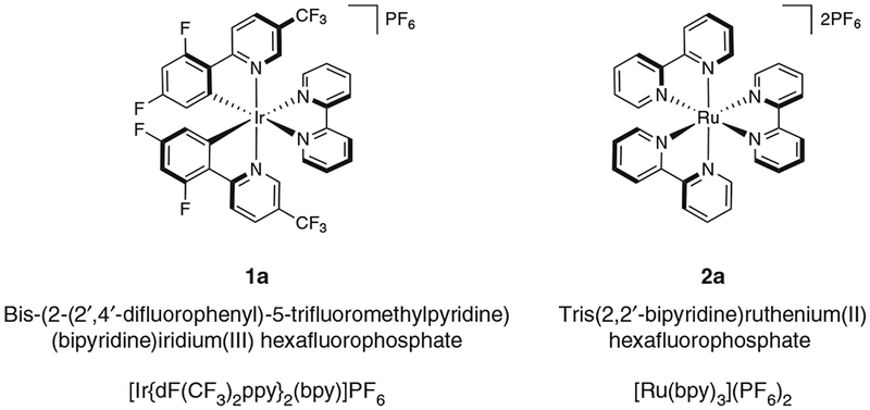
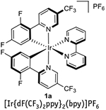
In recent advances, photocatalysts have been used for facilitating oxidation, cycloaddition, reduction, and radical addition-type reactions1–6. Although previous reviews have highlighted the use and advantages of both transition-metal1–3,5–6 and fully organic photoredox catalysts4, the former class of catalysts will be the focus of this protocol. Specifically, methods to prepare two of the most commonly used organometallic photocatalysts (1a and 2a, see Fig. 1) will be presented. Although organic photocatalysts are more sustainable and do not result in the generation of heavy-metal waste, transition-metal photocatalysts generally have longer excited-state lifetimes, have larger redox windows and, because of their efficiency, can be used at lower catalyst loadings.
Figure 1 |.
Structures of photocatalysts synthesized in this protocol.
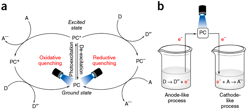
Photoredox catalysis is energetically driven by visible-light excitation of a photosensitizer to reach its photoexcited state. Although the vast majority of photorelaxation events from this state are unproductive (e.g., photon emission or internal, nonradiative de-excitation), intermolecular reductive or oxidative quenching can also occur (Fig. 2)6,8. This type of relaxation provides the mechanistic backbone for photoredox catalysis. In reductive quenching, the photoexcited state of the photocatalyst (PC*) oxidizes an electron donor (D) by way of a SET oxidation (Fig. 2a). To return to its original oxidation state, the newly reduced catalyst undergoes oxidation by an electron acceptor (A)3,6. Any interaction between D and A (electron transfer, H-atom abstraction, radical-radical coupling, and so on) is independent of the photocatalyst itself. Alternatively, in oxidative quenching, the steps are reversed, with the excited-state photocatalyst undergoing one-electron oxidation first, and then undergoing reduction, which causes the photocatalyst to return to its ground state. Regardless of the operative quenching pathway, when taken together, these two events mimic an electrochemical cell: the substrate undergoing reduction represents the cathode reaction, the substrate undergoing oxidation represents the anode reaction, and the photocatalyst serves as the wire facilitating electron transfer (Fig. 2b). The clearly defined electrochemical potentials provide enhanced predictive power when approaching novel transformations3. Using a combination of electrochemical, spectroscopic, and computational techniques, the electrochemical attributes of both the excited and ground states of photocatalysts can be determined (Table 1; refs. 1–3,5,6,9–12). In general, iridium photocatalysts have achieved a privileged position among photoredox catalysts, due to their highly desirable photophysical properties. They possess much larger ‘redox windows’ (i.e., the voltage range of oxidative and reductive quenching of the photoexcited catalyst), thus enabling a wider array of redox process to be accomplished, and longer excited-state lifetimes than their ruthenium counterparts; furthermore, their photophysical/electrochemical properties are more tunable by way of ligand-sphere modifications. Despite these marked advantages, the high cost of iridium (due to its scarcity in nature) has driven chemists to explore the relevant properties of other, less-precious, metals and organic dyes4. In addition, the synthesis of many of the typically used iridium photocatalysts is undoubtedly more laborious than that of the more common ruthenium photocatalysts. This is especially true for photocatalyst 1d (Table 1), whose synthesis is performed at temperatures exceeding 200 °C, and for which chromatography, rather than simple precipitation is the standard purification method12. Ultimately, the choice of photocatalyst depends on a careful balance of electrochemical performance, cost, and practicality1–3.
Figure 2 |.
Redox reactions of photocatalysts. (a) Simplified cycles for both reductive and oxidative photocatalyst quenching, (b) Features of the ‘virtual’ electrochemical cell, to which the process of photoinduced electron transfer can be viewed as analogous.
TABLE 1 |.
Photophysical properties of common iridium and ruthenium photoredox catalysts.
| Photocatalyst (common abbreviation) |
λmax (nm) |
Excited-state lifetime (ns) |
E1/2+PC/*PC (V vs SCE) |
E1/2*PC/−PC (V vs SCE) |
E1/2+PC/PC (V vs SCE) |
E1/2PC/−PC (V vs SCE) |
References |
|---|---|---|---|---|---|---|---|
 |
379 | 2,280 | −1.00 | +1.32 | +1.69 | −1.37 | 2,9,10 |
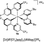 |
380 | 2,300 | −0.89 | +1.21 | +1.69 | −1.37 | 2,3 |
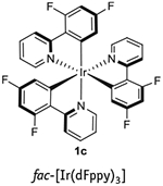 |
346 | 1,600 | −1.48 | +0.76 | +1.28 | −2.01 | 1,12 |
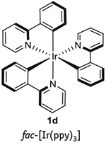 |
375 | 1,900 | −1.73 | +0.31 | +0.77 | −2.19 | 1,3 |
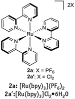 |
452 | 1,100 | −0.81 | +0.77 | +1.29 | −1.33 | 1,3,6 |
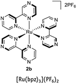 |
443 | 740 | −0.26 | +1.45 | +1.86 | −0.80 | 1,3,6 |
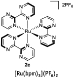 |
454 | 131 | −0.21 | +0.99 | +1.69 | −0.91 | 3 |
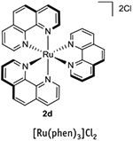 |
422 | 500 | −0.87 | +0.82 | +1.26 | −1.36 | 1,3 |
Photocatalysts in dual catalytic processes
Although photoredox catalysis has already proven to be an extraordinarily powerful paradigm, recent developments have further advanced the field, namely, the introduction of dual catalysis between a visible-light-activated photoredox catalyst and another catalytic cycle7,13–16. In the dual catalytic variant, one of the SET events is an essential mechanistic step in a second catalytic cycle, whether the cycle is organocatalytic or organometallic in nature. Recently, our laboratory and others have been involved in the latter: integration of transition metal catalysis with photoredox catalysis17–50. By exploiting the propensity of photoredox catalysts to promote SET events to generate Csp3 (ref. 3) radicals, as well as the propensity of these radicals to undergo metalation in the presence of various transition metals, a range of highly useful, yet challenging, coupling processes can be accomplished under remarkably mild conditions. This is in stark contrast to the classic catalytic approaches, in which harsh conditions (strongly alkaline reaction solutions, high temperatures) are needed when using process-friendly, bench-stable reagents (e.g., organoboron or organosilicon reagents). Alternative, milder conditions can be used if more-reactive nucleophiles (e.g., organozinc, organomagnesium, or organolithium reagents) are used, at the expense of functional group tolerance.
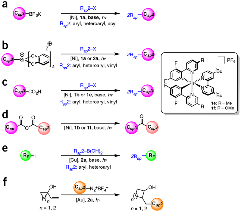
The simple yet powerful nature of this dual catalysis paradigm has led to a series of reports on its application in the context of the cross-coupling of benzylic17,20,33–37, secondary alkyl18,33–36, α-alkoxy21,24,27,36, and α-amino23,24,27 Csp3-hybridized radicals typically with aryl electrophiles, although alkenyl27,34 and/or acyl23 electrophiles, have also been reported. These radicals are generated through SETs from oxidizable precursors such as organotrifluoroborates17–23, carboxylic acids24–27, and alkylsili-cates33–37 (Fig. 3). Very recently, activated C-H bonds have been identified as radical progenitors when used in conjunction with a hydrogen atom abstractor29. Note that the choice of photocatalyst in all these reactions depends on the excited-state oxidation potentials (E1/2 PC*/PC–) and their respective reduced ground-state reduction potentials (E1/2 PC/PC–). Hence, activated carboxylic acids and alkyltrifluoroborates (average E1/2 of + 1.00 V and + 1.25 V, respectively) and nickel (E1/2 of NiI/0 ≥ – 1.10 V) necessitate the use of 1a or 1b (refs. 17,24). On the other hand, the relatively lower oxidation potential of silicates (E1/2 ~ + 0.4 to + 0.75 V versus saturated calomel electrode (SCE)) permits 2a to be used in addition to 1a or 1b (refs. 33–37).
Figure 3 |.
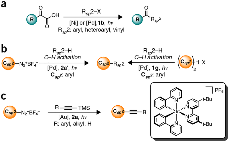
Summary of representative Csp3-Csp2 bond formation processes via Ni, Cu, and Au photoredox cross-coupling dual catalysis, (a) Molander: trifluoroborates (Ni), refs. 17–23; (b) Fensterbank, Molander: silicates (Ni), refs. 33–37; (c) MacMillan & Doyle: carboxylic acids (Ni), refs. 24,27; (d) MacMillan: mixed anhydrides (Ni), ref. 25; (e) Sanford: trifluoromethyl iodide (Cu), ref. 31; and (f) Toste: Diazoniums (Au), ref. 39.
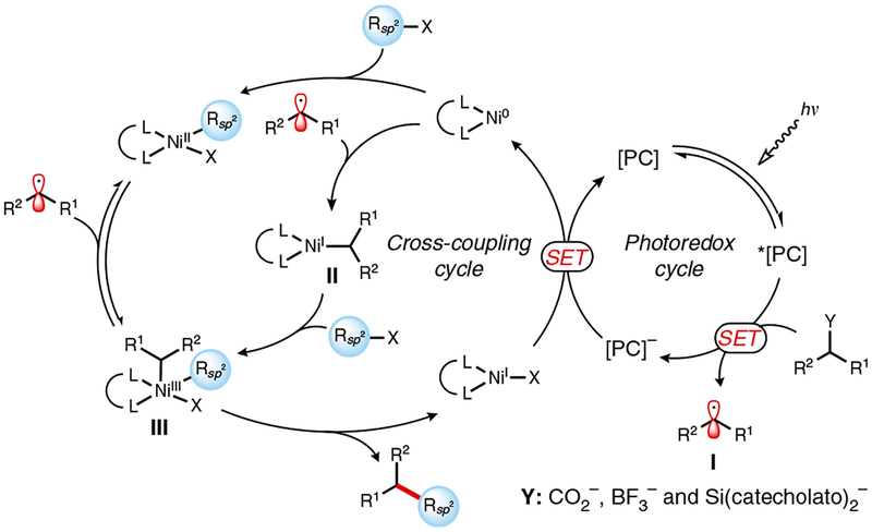
Mechanistically, reductive quenching of the excited state of the photocatalyst (e.g., la, lb, le, If, or 2a) by the radical precursor generates radical I (Fig. 4). Subsequent metalation of this radical with a nickel(0) complex generates complex II, in which the transition metal center is formally oxidized by a single electron19. Alternatively, oxidative addition by the nickel into a Csp2–X bond may precede radical addition to the metal center. Irrespective of the step order, however, both pathways converge on the formation of intermediate III, which undergoes rapid reductive elimination, furnishing the desired Csp2–Csp2 cross-coupled product, and a NiI–X complex. Single-electron reduction of NiI–X by the reduced form of the ground-state photocatalyst then completes the dual catalytic process. Despite its relative complexity, the process just described is self-regulating, because turnovers of the transition metal catalyst and photocatalyst are inextricably linked to each other, thus moderating radical formation and preventing undesired side reactions.
Figure 4 |.
Proposed mechanism of photoredox/nickel dual catalytic Csp3-Csp2 cross-coupling.
Before the advent of photoredox/nickel dual catalytic Csp3–Csp2 cross-coupling, copper and gold catalysts had been integrated in dual catalysis to forge these same types of bonds (Fig. 3). Radicals generated from either diazonium salts or perfluoroalkyl iodides were reported in conjunction with these metals31,39. The first step in photoredox/nickel dual catalytic Csp3–Csp2 cross-coupling systems, unlike in the previous cycle (Fig. 4), was proposed to be oxidative quenching of the excited state of the photocatalyst by the radical precursor. Subsequent metalation of the radical is followed by either reductive elimination, then oxidation of the metal center, or vice versa. The reduction potentials of diazonium salts (E1/2 = −0.1V for PhN2 + BF4–)3 and perfluoroalkyl iodides (E1/2 = −1.22 V for CF3I)31 enable the use of 2a and 2a′ as photocatalysts. Because of mechanistic disparities between our devised Ni system and these approaches, different nucleophiles and electrophiles can be used and thus alternative structures can be accessed.
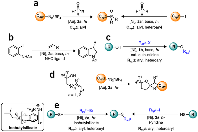
A number of other linkages can be constructed using this dual catalytic manifold (Figs. 5 and 6) Csp2–Csp2 bonds can be formed using palladium or nickel catalysts in conjunction with α-ketoacids, diaryliodonium salts, or diazonium salts as radical precursors26,30,46. Recently, the formation of Csp2–Csp bonds has been achieved via photoredox dual catalysis using 2a and a gold catalyst38. Similarly, examples of Csp3–Csp3 coupling via decarboxylative allylation have also been recently reported49–50. Csp2–Y (Y = heteroatom) bonds can also be forged using either gold or nickel catalysts with aryl halides, olefins, or diazonium salts serving as coupling partners28,31,41,42,44,45. Using this same general approach, a range of carbon-heteroatom bonds can be forged, including C–N (refs. 41,44), C–O (refs. 24,28), C–P (refs. 40,45), and C–S (refs. 47,48) bonds. Dual catalytic methods for formation of both Csp2–Csp2 and Csp2–Y bonds work by either of the two mechanisms discussed in the previous paragraphs. The only exceptions are the etherification reported by MacMillan28 and the amination reported by Jamison44, in which nickel is posited to be oxidized and then reduced during dual catalytic cycles. In these two cases, therefore, nickel is acting both as an electron donor and an acceptor.
Figure 5 |.
Current progress made in photoredox dual catalytic cross-coupling reactions for the formation of Csp2-Csp2 and Csp2-Csp bonds, (a) MacMillan, Fu: α-ketoacids (Ni, Pd), ref. 26; (b) Sanford: diazonium and diaryliodonium salts (Pd), refs. 30,32; and (c) Toste: diazoniums (Au), ref. 38.
Figure 6 |.
Current progress made in photoredox dual catalysis cross-coupling reactions for the formation of Csp2-Y bonds, (a) Toste, Xiao: phosphination (Ni, Au), refs. 40,45; (b) Jamison: arylation/amination/cyclization (Ni), ref. 44; (c) MacMillan: etherification (Ni), ref. 28; (d) Glorius: arylation and etherification/cyclization (Au), ref. 41; and (e) Molander, Johannes: thioetherification (Ni), refs. 47,48.
Rationale for synthesizing photocatalysts in-house
As part of our efforts to explore photoredox dual catalytic methods for Csp3–Csp2 and Csp2–Y bond formation, our group routinely uses 1a and 2a as photocatalysts. Although these species are used in catalytic quantities (typically 1–5 mol%), their high molecular weight necessitates the consumption of sizable quantities when evaluating substrate scope and/or scaling up reactions. As a consequence, it is far less expensive to prepare 1a or 2a in-house using the optimized procedures presented in this article than to purchase them from commercial suppliers.
For example, the price of 1a from standard commercial suppliers is ~$l, 400/g, whereas material costs amount to ~$160/g using the present protocol. Similarly, although 2a can be purchased for ~$134/g from standard commercial suppliers, the chemicals needed for its synthesis cost ~$34/g following the approach detailed in this protocol.
Experimental design
Synthesis of 1a requires two ligand modifications, followed by an anion metathesis (Fig. 7). Please note that ligand 3a, which is necessary for the synthesis of 1a, is not available from major commercial suppliers, and thus must be prepared via a Suzuki cross-coupling following the directions in Box 1, in advance of implementing Step 1A(i-1vii) of the PROCEDURE. Synthesis of 2a, which is described in Step lB(i-xxiv) of the PROCEDURE, in contrast, is much simpler than that of 1a, as it is only one chemical step and a counter-ion exchange (Fig. 8). The syntheses of both 1a and 2a are quite scalable and can probably be adapted for the synthesis of other related photocatalysts. For example, 1b can be prepared by the same route described for the preparation of 1a (Step 1A(i-lvii) of the PROCEDURE) simply by replacing 2,2′-bipyridyl with 4,4′-di-tert-butyl-2,2′-bipyridyl51. In Box 2, we provide directions for a representative use of 1a in the context of dual catalysis using an alkyltrifluoroborate as a radical precursor. Furthermore, in Box 3 we provide directions for a representative application of 2a in the context of dual catalysis using an alkylsilicate as a radical precursor. In addition, we have included step-by-step instructions on how to perform two traditional photoredox reactions as a way to test the catalytic effectiveness of 1a and 2a thus prepared: a photoredox variant of an Appel reaction using 2a, an approach first described by the Stephenson group52 (Box 4), and a Giese-type addition of a benzyl radical (generated from a benzyltrifluoroborate) to methyl vinyl ketone, reported by Akita and colleagues53 using 1a (Box 5).
Figure 7 |.
Preparation of iridium photoredox catalyst 1a.
Box 1 |. Preparation of ligand 3a via a Suzuki cross-coupling ● TIMING 24 h.
Ligand sphere modifications have substantial effects on the photoredox properties of Ru- and Ir-based photocatalysts. In particular, 2-phenyl-2-pyridyl (ppy) derivatives are ligands commonly used when constructing Ir-based photocatalysts, given their amenability to undergoing cyclometalation and to enhancing the lifetime of the excited state, as well as the redox window of the metal complexes they form. Below, the synthesis of the highly fluorinated 2-phenyl-2-pyridyl ligand 3a, which is required for the synthesis of Ir-photocatalyst 1a, is described. Ligand 3a substantially improves the oxidative potential and excited-state lifetime of the Ir catalyst with respect to its nonfluorinated analog, at the expense of the complex’s reductive capabilities (Table 1).

Additional materials
Tetrahydrofuran (THF; Fisher Scientific, cat. no. T425–4)
Tetrakis(triphenylphosphine)palladium(0) (Pd(PPh3)4; Sigma-Aldrich, cat. no. 216666)
Anhydrous potassium carbonate (K2CO3; Fisher Scientific, cat. no. P208–500)
2-Bromo-5-(trifluoromethyl)pyridine (Matrix Scientific, cat. no. 1382)
2,4-Difluorophenylboronic acid (Matrix Scientific, cat. no. 5591)
Brine (saturated sodium chloride solution)
Anhydrous sodium sulfate (Na2SO4; Fisher Scientific, cat. no. S429–500)
Silica gel (Flash Silica Gel, 60-Å porosity, 32–63 μm; Dynamic Adsorbants)
Deuterated chloroform (CDCl3; Cambridge Isotope Laboratories) for NMR
Dichloromethane (CH2Cl2; 99.5% (vol/vol); Fisher Scientific, cat. no. D37–4)
Ethyl acetate (Et0Ac; 99.9% (vol/vol); Fisher Scientific, cat. no. E195–4)
Procedure
In a one-neck, 100-ml round-bottom flask containing a Teflon-coated stir bar, weigh out 4.79 g of 2,4-difluorophenylboronic acid (30 mmol, 1.5 equiv.).
Add 4.52 g of 2-bromo-5-(trifluoromethyl)pyridine (20 mmol, 1.0 equiv.) to the round-bottom flask prepared in the previous step.
Add 13.82 g of K2CO3 (100 mmol, 5.0 equiv.) to the reaction mixture.
Add 2.31 g of Pd(PPh3)4 (2 mmol, 0.1 equiv.) to the flask.
Equip the flask with a Liebig reflux condenser. Ensure that water is flowing at an appreciable rate through the condenser.
Seal the condenser with a rubber septum, and place the reaction mixture under vacuum for 1 min via an inlet needle.
Refill the system with argon.
Perform three such evacuation-backfill cycles, so that the flask and its contents are eventually under an argon atmosphere.
Add 67 ml of THF and 33 ml of deionized H2O to the flask.
-
Stir the reaction mixture vigorously for 24 h at 80 °C. (The solution should be at reflux during the course of the reaction.)
▲ CRITICAL STEP If the experimenter is uncertain when the reaction has reached completion, we recommend that the crude reaction mixture be analyzed by thin-layer chromatography (TLC), gas chromatography-mass spectrometry (GC-MS), and/or HPLC.
After 24 h, let the reaction flask cool to room temperature.
Upon reaction completion, transfer the reaction mixture to a separatory funnel and add 200 ml of deionized H2O to the funnel.
-
Add 200 ml of diethyl ether to the separatory funnel and shake the it vigorously.
! CAUTION Vent the separatory funnel repeatedly during this and each future shaking process to avoid gas buildup.
Once the organic and aqueous layers separate, transfer the organic layer and the aqueous layer to two separate 500-ml Erlenmeyer flasks.
Place the aqueous layer back into the separatory funnel and add 50 ml of diethyl ether to it.
Shake the separatory funnel vigorously and, once the organic and aqueous layers separate, transfer the organic layer and the aqueous layer to their respective 500-ml flasks.
Repeat steps 14 and 15 two more times.
Transfer the combined organic layers to the separatory funnel and add 200 ml of H2O to it.
Shake the separatory funnel vigorously and, once the organic and aqueous layers separate, discard the aqueous layer in the appropriate waste container.
Add 200 ml of brine to the separatory funnel and shake it vigorously.
Once the organic and aqueous layers separate, discard the aqueous layer in the appropriate waste container.
Transfer the organic layer to a 500-ml flask, and dry the organic solution over solid Na2SO4 (~20 g) for 10 min while gently shaking the flask.
Once dry, decant the organic solution to a 1-liter round-bottom flask and remove the solvent by rotary evaporation (40 °C,250 mmHg, ~20 min).
Add 100 ml of dichloromethane and 10 g of silica gel to the now-concentrated material. Gently swirl the flask. Remove the solvent in vacuo by rotary evaporation to ‘dry-pack’ the crude product onto silica (38 °C, 200 mmHg, ~20 min).
Pack a 350-ml medium-porosity fritted funnel with ~100 ml of silica. Place a circular piece of filter paper (~8.5 cm in diameter) on top of the packed silica (column size: 9 cm × 3 cm).
Place the now dry-packed material atop the filter paper, and place another similarly sized piece of filter paper atop the dry packed material.
Elute the desired ligand using a 95:5 (by volume) mixture of hexanes/ethyl acetate (~250 ml), followed by a 9:1 (by volume) mixture of hexanes/ethyl acetate (~100 ml) prepared in advance in a 500-ml round-bottom flask (where Rf = 0.46 (9:1 Hex/EtOAc).
Remove the solvent from the eluate in vacuo by rotary evaporation (40 °C, 120 mmHg, ~20 min) to obtain pure product in 88% isolated yield (4.58 g).
■ PAUSE POINT The product is stable indefinitely under atmospheric conditions at room temperature.
ANTICIPATED RESULTS
2-(2,4-difluorophenyl)-5-(trifluoromethyl)pyridine, 3a, appears as a white, highly crystalline solid obtained in an 88% yield.
Analytical data
1H NMR (CDCI3, 500 MHz) δ 6.95 (ddd, J = 11.3, 8.9, 2.4 Hz, 1H), 7.04 (td, J = 8.2, 2.1 Hz, 1 H), 7.91 (d, J = 8.2 Hz, 1H), 7.99 (dd, J = 8.4, 1.7 Hz, 1H), 8.06 – 8.13 (m, 1H), 8.96 (s, 1H).
13C NMR (CDCI3, 125 MHz) δ 104.9 (dd, J = 26.7, 26.1 Hz, CH), 112.5 (dd, J = 21.1, 3.7 Hz, CH), 123.9 (q, J = 272.2 Hz, CF3), 122.7 (dd, J = 11.0, 3.7 Hz, C), 123.9 (d, J = 11.0 Hz, CH), 125.4 (q, J = 33.0 Hz, C), 132.7 (dd, J = 10.1, 3.7 Hz, CH), 134.0 (q, J = 2.7 Hz, CH), 146.8 (q, J = 3.9 Hz, CH), 156.0 (C), 161.3 (dd, J = 253.9, 11.9 Hz, CF), 164.2 (dd, J = 252.9, 12.8 Hz, CF).
19F NMR (CDCI3, 125 MHz) δ −115.14 (d, J = 9.2 Hz, IF), −110.35 (d, J = 9.2 Hz, IF), −65.53 (s, 3F). Infrared spectroscopy (IR) (cm−1, neat, attenuated total reflection IR (ATR)) 3,051, 1,599, 1,477, 1,326, 1,119, 1,081, 856, 817, 719.
High-resolution mass spectrometry (HRMS) (electrospray ionization, positive collection (ES+)) calc. for C12H7F5N (M + H): 260.0499, found 260.0500.
Figure 8 |.
Preparation of ruthenium photoredox catalyst 2a.
Box 2 |. Photoredox cross-coupling of a sterically hindered secondary alkyltrifluoroborate salt with a heteroaryl bromide ● TIMING 24 h.
Recently, our group and others have reported a number of photoredox-Ni cross-coupling reactions that have been transformative of the approaches to forging Csp3–Csp2 bonds under mild conditions17–23,24,27,29,33–37. In particular, the cross-coupling of secondary alkyltrifluoroborates with (hetero)aryl halides using photocatalyst 1a has proven to be a robust method18, tolerating the presence of heteroatom-containing organotrifluoroborates and sterically hindered substrates, without competitive isomerization. To illustrate this approach, we describe herein the cross-coupling between 3-bromo-5-methoxypyridine and 2-methylcyclopentyltrifluoroborate using photocatalyst 1a. This example is representative of the yields that can be achieved using various secondary alkyltrifluoroborates with aryl and heteroaryl bromide substrates. However, it should be noted that yields are poorer than those alluded to here for electron-rich substrates (e.g., bromoanisole) and that some substrates, such as 4-bromo-N,N-dimethylaniline, are unreactive in the conditions described herein.

Additional materials
1,4-Dioxane, 99.5% (vol/vol) (Acros, cat. no. 268340010), for HPLC, degassed in a manner identical to that described for ethanol in the PROCEDURE
[Ir{dF(CF3)2ppy}2(bpy)]PF6, photocatalyst 1a, prepared as described in the main PROCEDURE
Cesium carbonate (Cs2C03; Acros Organics, cat. no. AC19204)
! CAUTION Cesium carbonate is irritating to the eyes, respiratory system, and skin.
3-Bromo-5-methoxypyridine (Sigma-Aldrich, cat. no. 631817)
! CAUTION It is corrosive to metals, acutely toxic on ingestion, and irritating to the eyes, skin, and respiratory system.
4,4′-Di-tert-butyl-2,2′-dipyridyl (dtbbpy; Sigma-Aldrich, cat. no. 515477)
! CAUTION It is irritating to the skin and eyes, and may cause respiratory irritation on inhalation.
Nickel(II) chloride, dimethoxyethane adduct [NiCl2(dme)] (Strem, cat. no. 93–2801)
! CAUTION It is toxic if swallowed, and it may cause asthma if inhaled. It is irritating to the eyes, skin, and respiratory system, and is a possible mutagen. Keep it dry and under inert gas (if possible).
Potassium trans-2-methylcyclopentyltrifluoroborate (Frontier Scientific, cat. no. P10495)
! CAUTION It is a possible eye and skin irritant.
Automated chromatographic machine (Teledyne CombiFlash Rf (visualizing at 254 nm, monitoring at 280 nm))
Prepacked 40-g silica gel column, 60-Å porosity, 20–40 μm (Isco Teledyne Redisep Rf Gold Flash Cartridges, cat. no. 692203347)
Precolumn with frits (Isco Teledyne, cat. no. 693873235)
Test tubes for collection of fractions during chromatographic separation, borosilicate glass, 16 × 150 mm (Fisher Scientific, cat. no. 14–961-31)
Deuterated chloroform (CDCl3; Cambridge Isotope Laboratories) for NMR
Procedure
In a 150-ml round-bottom flask equipped with a Teflon-coated stir bar, weigh out 29 mg of [NiCl2(dme)] (0.133 mmol, 0.025 equiv.).
Add 36 mg of dtbbpy (0.13 mmol, 0.025 equiv.) and 5 ml of THF to the flask, and then seal it with a rubber septum.
Place the reaction mixture under argon via an inlet needle.
-
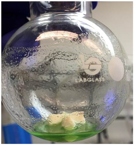
Gently heat the reaction mixture with a heat gun or an oil bath up to ~45 °C, until the mixture turns into a homogeneous green solution.
▲ CRITICAL STEP Complexation to generate the bipyridyl Ni pre-catalyst, which becomes apparent with the formation of the green solution, is essential. Although it is somewhat time-consuming, no reaction will occur unless this step is completed.
-
Place the reaction mixture under vacuum via the inlet needle to remove the solvent, yielding a pale, green-colored residue of ligated nickel complex (see photograph above).
▲ CRITICAL STEP Care should be taken when removing the atmosphere of the flask to avoid ‘bumping’ of the nickel complex into the vacuum line, thus diminishing the amount of active catalyst in solution.
After the residue has fully dried, refill the flask with argon.
Remove the septum and add 1.00 g of 3-bromo-5-methoxypyridine (5.32 mmol, 1.0 equiv.) to the flask.
Add to the flask, in the mentioned order, 1.52 g of potassium 2-trans-methylcyclopentyltrifluoroborate (7.98 mmol, 1.5 equiv.),2.59 g of Cs2CO3 (7.98 mmol, 1.5 equiv.), and 53 mg of iridium photocatalyst 1a (0.053 mmol, 0.01 equiv.).
Reseal the flask with a rubber septum and place the contents under vacuum for 1 min via an inlet needle.
Refill the flask with argon.
Perform three such evacuation-backfill cycles, so that the flask and its contents are eventually under an argon atmosphere.
Add 100 ml of dry, degassed 1,4-dioxane to the flask under an inert atmosphere.
-
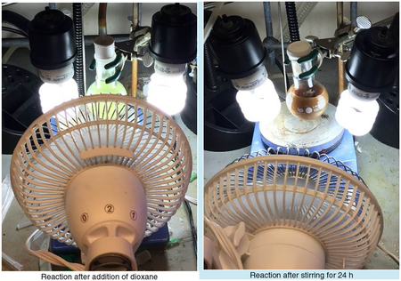
Place the flask in close proximity (6–10 cm) to two lit 26-W fluorescent light bulbs in their appropriate lamps (see image below) and stir the flask contents constantly (>500 r.p.m.). A fan should blow across the setup to ensure the vessel remains at an ambient temperature (<25 °C).
▲ CRITICAL STEP At an ambient temperature ≥25 °C, H-atom abstraction products (i.e., 2-arylated dioxanes) will often be observed.
-
Monitor the reaction for conversion of the starting material using TLC, GC-MS, or HPLC, until all the aryl bromide has been consumed (16–24 h). The color of the reaction mixture will change from pale yellow to dark brown as the reaction reaches completion.
Filter the reaction mixture through a 2 × 4 inch plug of Celite atop a 350-mL Büchner funnel, into a 500-mL round-bottom flask.
Rinse the plug with ~200 mL of dichLoromethane.
Remove the solvent by rotary evaporation (38 °C, 200 mmHg, ~20 min).
Add 100 mL of dichLoromethane and 1.5 g of silica gel to the now-concentrated material. Gently swirl the flask. Remove the solvent in vacuo by rotary evaporation to “dry-pack” the crude product onto siLica (38 °C, 200 mmHg, ~20 min).
Place the now dry-packed material in the precolumn and seal it with the appropriately sized frit.
Using an automated chromatographic machine, elute the desired product through the precolumn and a 40-g prepacked silica column using a 7:3 (by volume) mixture of hexanes/ethyl acetate into test tubes (Rf = 0.17 (9:1 Hex/EtOAc)).
Transfer the fractions containing the product to a round-bottom flask and remove the solvent from the eluate in vacuo by rotary evaporation (40 °C, 120 mmHg, ~25 min) to obtain pure product in an 89% isolated yield (1.02 g).
■ PAUSE POINT The product is stable for at least 1 year under atmospheric conditions at room temperature.
ANTICIPATED RESULTS
3-Methoxy-5-(trans-2-methylcyclopentyl)pyridine prepared using the present procedure is obtained as brown, translucent crystals in an 89% yield.
Analytical data
1H NMR (CDCl3, 500 MHz): δ 0.91 (d, J = 6.5 Hz, 3H), 1.29–1.31 (m, 1H), 1.69–1.76 (m, 3H), 1.89–1.95 (m, 1H), 1.98–2.01 (m, 1H), 2.07–2.09 (m, 1H), 2.38–2.43 (m, 1H), 3.84 (s, 3H), 7.01–7.03 (m, 1H), 8.06–8.08 (m, 1H), 8.12 (d, J = 2.5 Hz, 1H).
13C NMR (CDCI3, 125 MHz): δ18.5 (CH3), 24.0 (CH2), 34.8 (CH2), 35.3 (CH2), 43.2 (CH), 51.7 (CH), 55.6 (CH3), 119.6 (CH), 134.8 (CH), 141.6 (C), 142.2 (CH), 155.8 (C).
IR (cm−1, neat, ATR) 2,953, 2,868, 1,587, 1,454, 1,427, 1,318, 1,296, 1,176, 1,164, 1,049, 867, 714.
HRMS: (ES+) calc. for C12H18NO (M+H) 192.1388; found: 192.1386.
Box 3 |. Cross-coupling of primary alkylsilicate with 1-bromonaphthalene via photoredox/nickel dual catalysis ● TIMING 24 h.
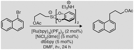
Although alkyltrifluoroborates have proven to be suitable precursors in cross-coupling reactions proceeding via photoredox-Ni dual catalysis, our laboratory and others have recently shown that hypervalent alkyl bis(catecolato)silicates can also act as radical sources in the same reaction context33–37. Alkylsilicates are very useful radical precursors for three reasons: first, an array of alkyl radicals can be generated that includes primary (1°) radicals, which cannot typically be accessed from the corresponding organotrifluoroborate; second, as their oxidation potentials are lower than those of the corresponding organotrifluoroborates, the less expensive, more readily accessible Ru photocatalyst 2a can be used alongside the iridium-based photocatalyst 1a; third, the innocuous reaction by-products allow the reaction to be conducted in the absence of any Lewis basic additive, which is typically required for reactions involving carboxylic acids or organotrifluoroborates. To illustrate the utility of both alkylsilicates and 2a, we describe in this box a photoredox cross-coupling between 1-bromonaphthalene and triethylammonium bis(catecholato) (3-acetoxypropyl)silicate. This example is representative of the yields that can be achieved using various silicates with aryl bromide substrates. However, it should be noted that yields are somewhat lower for systems involving heteroaryls, and some substrates (e.g., 4-bromo-N,N-dimethylaniline) are unreactive in the described context.
Additional materials
Triethylammonium bis(catecholato)(3-acetoxypropyl)silicate (prepared as reported by Jouffroy et al.33)
! CAUTION This compound is possibly harmful upon ingestion, inhalation or contact with skin, and it is an irritant.
1-Bromonaphthalene (Sigma-Aldrich, cat. no. B73104)
! CAUTION It is flammable; harmful upon ingestion, inhalation, or contact with skin; and an irritant.
4,4′-Di-tert-butyl-2,2′-dipyridyl, dtbbpy (Sigma-Aldrich, cat. no. 515477)
! CAUTION This compound is irritating to skin and eyes, and it may cause respiratory irritation upon inhalation.
Nickel(II) chloride, dimethoxyethane adduct [NiCl2(dme)] (Strem, cat. no. 93–2801)
! CAUTION This compound is toxic if swallowed, and it may cause asthma if inhaled. It is irritating to eyes, skin, and respiratory system, and it is a possible mutagen. Keep it dry and under inert gas if possible.
N,N′-Dimethylformamide (DMF; 99.8% (vol/vol), extra dry over molecular sieves; Acros, cat. no. 348431000)
[Ru(bpy)3](PF6)2, photocatalyst 2a, prepared as described in the main PROCEDURE
2 M Sodium hydroxide solution
! CAUTION Sodium hydroxide solution is caustic, harmful to skin and eyes, and may cause respiratory irritation upon inhalation.
2 M Hydrochloric acid solution
! CAUTION HCl solution is corrosive, harmful to skin and eyes, and may cause respiratory irritation upon inhalation.
Brine (saturated sodium chloride solution)
Anhydrous sodium sulfate (Na2SO4; Fisher Scientific, cat. no. S429–500)
Silica gel, 60-Å porosity, 32–63 μm (Dynamic Adsorbants Flash Silica Ge)
! CAUTION Silica gel is harmful upon inhalation, and it is an irritant.
Deuterated chloroform (CDCl3; Cambridge Isotope Laboratories) for NMR
Dichloromethane (CH2Cl2; 99.5% (vol/vol); Fisher Scientific, cat. no. D37–4)
Ethyl acetate (EtOAc; 99.9% (vol/vol); Fisher Scientific, cat. no. E195–4)
Procedure
In a 100-ml round-bottom flask containing a Teflon-coated stirring bar, weigh out 50.1 mg of [NiCl2(dme)] (0.242 mmol, 0.05 equiv.).
Add 64.8 mg of dtbbpy (0.242 mmol, 0.05 equiv.) and 10 ml of THF to the flask. Seal the flask with a rubber septum and place the reaction mixture under argon via an inlet needle.
-
Gently heat the reaction mixture with a heat gun or an oil bath (~45 °C) until the mixture forms a homogeneous green solution (see Box 2 for an image of this solution).
▲ CRITICAL STEP Unlike for the procedure detailed in Box 2, this step is not essential for reaction success. However, if this step does not go to completion, the reaction may occur at a slower pace than it would otherwise, and the yield of the reaction may be diminished.
-
Place the reaction mixture under vacuum via the inlet needle to remove the solvent and to yield a pale, green-colored residue of ligated nickel complex.
▲ CRITICAL STEP Care should be taken when removing the atmosphere of the flask to avoid ′bumping′ of the nickel complex into the vacuum line, thus diminishing the amount of active catalyst in solution.
Refill the flask with argon.
Once the residue is fully dry, remove the septum and add 2.60 g of triethylammonium bis(catecholato)(3-acetoxypropyl)silicate (5.80 mmol, 1.20 equiv.) and 83 mg of 2a (0.096 mmol, 0.02 equiv.) to the flask.
Reseal the flask with a rubber septum and place the contents under vacuum for 1 min via an inlet needle.
Refill the flask with argon.
Perform three such evacuation-backfill cycles, so that the flask and its contents are eventually under an argon atmosphere.
Weigh out 1.00 g of 1-bromonaphthalene (4.83 mmol, 1.0 equiv.) into a 20-ml scintillation vial.
Dilute the 1-bromonaphthalene by adding 10 ml of DMF to the vial.
Transfer the contents of the vial to the flask via a syringe. Rinse the vial out with 5 ml of DMF and add this to the flask.
Add 34 ml more of DMF to the flask.
Place the flask in close proximity to two lit 26-W fluorescent light bulbs in their appropriate lamps and subject the flask contents to constant stirring (> 500 r.p.m.). A fan should blow across the setup to maintain the ambient temperature at ~25 °C.
Monitor the reaction for conversion of starting material using TLC, GC–MS, or HPLC until full consumption of the bromide has occurred (16–24 h). The color of the reaction mixture will change from bright red to dark brown (appearing similar to mud) as the reaction reaches completion.
Upon reaction completion, transfer the reaction mixture to a 500-ml separatory funnel and add to it first 150 ml of deionized H2O and then 100 ml of anhydrous Et2O; then shake the funnel vigorously.
Once the organic and aqueous layers separate, transfer the organic layer and the aqueous layer to separate 500-ml Erlenmeyer flasks.
Place the aqueous layer back into the separatory funnel and add to it 50 ml of Et2O.
Shake the separatory funnel vigorously and, once the organic and aqueous layers separate, transfer the organic layer and the aqueous layer to their respective 500-ml flasks.
Repeat steps 18 and 19 two more times.
Transfer the combined organic layers to the separatory funnel and add to it 100 ml of 2 M NaOH solution.
Shake the separatory funnel vigorously and, once the organic and aqueous layers separate, discard the aqueous layer in the appropriate waste container.
Repeat steps 21 and 22.
-
To remove residual dtbbpy ligand from the solution, add 100 ml of 2 M HCl solution to the separatory funnel, and repeat step 22.
▲ CRITICAL STEP When adapting this procedure for other substrates, steps 24 and 25 may be skipped if these substrates have basic residues that could react with HCl and thus be lost in these washes.
Add 100 mL of deionized H2O to the separatory funnel, and repeat step 22.
Add 100 mL of brine to the separatory funnel, and repeat step 22.
Transfer the organic Layer to a 500-mL flask and dry the organic solution over Na2SO4 (~20 g) for 10 min while gently shaking the flask.
Transfer the organic solution to a 1-liter round-bottom flask and remove the solvent by rotary evaporation (40 °C, 250 mmHg,~25 min).
Add 100 ml of dichloromethane and 2 g of silica gel to the now-concentrated material. Gently swirl the flask. Remove the solvent in vacuo by rotary evaporation to ″dry-pack″ the crude product onto silica (38 °C, 200 mmHg, ~20 min).
Pack a 60-ml Büchner fritted funnel with ~30 mL of silica. Place a circular piece of filter paper (~4.5 cm in diameter) on top of the packed silica (column size: 4.5 cm × 2 cm).
Place the now dry-packed material atop the filter paper and place another similarly sized piece of filter paper atop the dry packed material.
Elute the desired ligand using a 95:5 (by volume) mixture of hexanes/ethyl acetate (~100 mL), followed by a 9:1 (by volume) mixture of hexanes/ethyl acetate (~50 mL), into a 500-mL round-bottom flask (Rf = 0.24).
Remove the solvent from the eluate in vacuo by rotary evaporation (40 °C, 120 mmHg, ~25 min) to obtain pure product in a 93% isolated yield (1.03 g).
■ PAUSE POINT The product is stable indefinitely under atmospheric conditions at room temperature.
ANTICIPATED RESULTS
Following the directions in the present procedure, 3-(l-naphthyl)propyl acetate is obtained as a dear, yellow oil in a 93% yield.
Analytical data
1H NMR (CDCl3, 500 MHz) δ 2.06–2.14 (m, 2H), 2.09 (s, 3H), 3.17 (t, J = 7.6 Hz, 2H), 4.17 (t, J = 6.6 Hz, 2H), 7.33 (d, J = 6.7 Hz, 1H), 7.41 (t, J = 7.9 Hz, 1H), 7.49 (td, J = 7.0, 1.2 Hz, 1H), 7.53 (td, J = 7.3, 1.2 Hz, 1H), 7.73 (d, J = 8.2 Hz, 1H),7.87 (d, J = 7.6 Hz, 1H), 8.03 (d, J = 8.2 Hz, 1H).
13C NMR (CDCl3, 125 MHz) δ 20.9 (CH3), 29.2 (CH2), 29.4 (CH2), 64.0 (CH2), 123.5 (CH), 125.3 (CH), 125.4 (CH), 125.8 (CH), 126.0 (CH), 126.8 (CH), 128.8 (CH), 131.7 (C), 133.9 (C), 137.2 (C), 171.1 (C).
IR (cm−1, neat, ATR) 2,954, 1,733, 1,596, 1,510, 1,464, 1,434, 1,386, 1,232, 1,166, 1,038, 976, 950, 876, 791, 776, 734.
HRMS: (ES+) caLc. for C15H16O2Na [M+Na]+: 251.1048; found: 251.1049.
Box 4 |. Conversion of 3-phenyl-1-propanol to 3-phenyl-1-bromopropane via photoredox catalysis (● TIMING 24 h).
The visible-light-activated catalysts described herein (INTRODUCTION) were used in net-neutral redox processes in a number of laboratories with great success long before the development of Ni-photoredox dual catalysis. One of the leading groups in the area of photoredox catalysis, the Stephenson group, has reported a number of protocols to facilitate various transformations (oxidative cleavage, dehalogenation, and radical· cyclization, among others) mediated by 2a (refs. 1,3). One of their early successes with 2a was a photoredox variant of an Appel reaction52. To illustrate the utility of 2a in a photoredox reaction, we describe herein a representative reaction reported originally by the Stephenson research group52: conversion of 3-phenyl-1-propanoL to 3-phenyl-1-bromopropane. In addition to being a viable reaction for functional·group interconversion, this process could be used as a benchmark to establish that 2a, prepared through the approach described in the main PROCEDURE, is photoredox active. Note that the procedure detailed as follows can be extended to iodide synthesis, if NaI is used as an additive in place of NaBr.
![]()
Additional materials
3-phenyl-1-propanol (Sigma-Aldrich, cat. no. 140856)
! CAUTION This compound is an irritant.
Carbon tetrabromide (CBr4, Sigma-Aldrich, cat. no. C11081)
! CAUTION Carbon tetrabromide is harmful upon ingestion, inhalation, or contact with skin, and it is an irritant.
Sodium bromide (NaBr, Sigma-Aldrich, cat. no. 310506)
[Ru(bpy)3](PF6)2, photocatalyst 2a, prepared as described in the main PROCEDURE
N,N′-Dimethylformamide (DMF; 99.8% (vol/vol), extra dry over molecular sieves; Acros, cat. no. 348431000)
Blue LEDs (470-nm blue Light, 32918 mcd ft−1; superbrightLEDs.com, cat. no. NFLS-B60X3-WHT-LC2)
Brine (saturated sodium chloride solution)
Anhydrous sodium sulfate (Na2SO4; Fisher Scientific, cat. no. S429–500)
Silica gel, 60-Å porosity, 32–63 μm (Dynamic Adsorbants Flash Silica Gel)
! CAUTION Silica gel is harmful upon inhalation, and it is an irritant.
Deuterated chloroform (CDCl3; Cambridge Isotope Laboratories) for NMR
Screw-top 20-ml reaction vial with a cap containing a PTFE-lined silicone septum (Chemglass, cat. no. CG-4908–01)
Parafilm (M Laboratory Wrapping Film; Fisher Scientific, cat no. 13–374-12)
Procedure
In a 20-ml, screw-top reaction vial containing a Teflon-coated stirring bar, weigh out 8.6 mg of 2a (0.01 mmol, 0.01 equiv.).
Add 0.663 g of CBr4 (2 mmol, 2 equiv.) and 0.206 g of NaBr (2 mmol, 2 equiv.) to the flask.
Seal the vial with a cap containing a PTFE-lined silicone septum. Place the reaction mixture under argon via an inlet needle.
Place the reaction mixture under vacuum via the inlet needle to remove any oxygen.
Refill the flask with argon.
Perform three additional evacuation-backfill cycles, so that the contents of the reaction vial are eventually under an argon atmosphere.
Weigh out 0.136 g of 3-phenyl-1-propanol (1 mmol, 1 equiv.) into a 20-ml scintillation vial.
Dilute the 3-phenyl-1-propanol by adding 5 m1 of DMF to the vial.
Add the solution of 3-phenyl-l-propanol in DMF to the reaction vial using a syringe. Rinse the vial out with 5 ml of DMF and add the resulting solution to the reaction vial.
Remove the inlet needle and cover the cap with Parafilm.
Place the flask in close proximity to a circular strip of lit blue LEDs atop a stir plate with constant stirring (>400 r.p.m.). A fan should blow across the setup to maintain an ambient temperature (~25 °C).
Monitor the reaction for conversion of starting material using TLC, GC–MS, or HPLC until full consumption of the alcohol has occurred (~12 h). The reaction mixture color will change from bright red to a red-brown, as the reaction reaches completion.
Upon reaction completion, transfer the reaction mixture to a 500-ml separatory funnel and add to it 100 ml of deionized H2O.
Add 100 ml of Et2O to the funnel and shake the flask vigorously.
Once the organic and aqueous layers separate, transfer the organic layer and the aqueous layer to separate 500-ml Erlenmeyer flasks.
Place the aqueous layer back into the separatory funnel and add to it 50 ml of Et2O.
Shake the separatory funnel vigorously and, once the organic and aqueous layers separate, transfer the organic layer and the aqueous layer to their respective 500-ml flasks.
Repeat steps 16 and 17 two more times.
Transfer the combined organic layers to the separatory funnel and add to it 100 ml of deionized water.
Shake the separatory funnel vigorously and, once the organic and aqueous layers separate, discard the aqueous layer in the appropriate waste container.
Repeat steps 19 and 20.
Add 100 ml of brine to the separatory funnel and repeat step 20.
Transfer the organic layer to a 500-ml flask and dry the organic solution over Na2S04(~20 g) for 10 min while gently shaking the flask.
Transfer the organic solution to a 500-ml round-bottom flask and remove the solvent by rotary evaporation (35 °C, 250 mmHg,~25 min) to obtain the crude product as an orange oil.
Construct a pipette column by plugging the pipette with a small piece of a Kimwipe and loading silica gel into it (column dimensions: 4 cm × 0.5 cm).
Dissolve the crude product in 1 ml of pentane, and load the solution thus obtained carefully atop the column.
Elute the desired bromide product with 10 ml of pentane (Rf = 0.9 [pentane]). Collect the eluate into a 50-ml round-bottom flask.
Remove the solvent from the eluate in vacuo by rotary evaporation (38 °C, 250 mmHg, ~25 min), followed by further solvent removal under high vacuum (25 °C, < 1 mmHg, ~15 min) to obtain the desired pure product in a 78% isolated yield (0.167 g).
■ PAUSE POINT The product is stable under atmospheric conditions for at least 2 weeks at room temperature in the dark.
ANTICIPATED RESULTS
Following the directions in the present procedure, 3-Phenyl-1-bromopropane is obtained as a clear, colorless oil in a 78% yield.
Analytical data
1H NMR (CDCl3, 500 MHz) δ 2.15–2.24 (m, 2H) 2.80 (t, J = 7.32 Hz, 2H) 3.42 (t, J = 6.71 Hz, 2H) 7.20–7.26 (m, 3H) 7.29–7.35 (m, 2H).
13C NMR (CDCI3, 125 MHz) δ 33.3 (CH2), 34.3 (CH2), 34.4 (CH2), 126.4 (CH), 128.8 (CH), 128.8 (CH), 140.8 (C).
GC–MS (EI) 200 ([M]+, 81Br 41%), 198 ([M]+, 79Br 41%), 117 (11%), 91 (100%), 65 (13%), 51 (5%).
IR (cm−1, neat, ATR) 3,027 (vw), 2,938 (vw), 1,496 (w), 1,453 (w), 743 (s), 698 (vs), 667 (vs), 561 (w).
Box 5 |. Giese-type reaction of benzyl trifluoroborate and methyl vinyl ketone via photoredox catalysis ● TIMING 24 h.
One of the most important findings before our discovery of Ni-photoredox dual catalysis was that organotrifluoroborates underwent oxidation under photoredox conditions. Akita reported that, in the presence of 1a or 1b, a range of organotrifluoroborates undergo facile SET oxidation53. The resulting alkyl radicals could then be captured in a Michael-like addition into electron-deficient olefins. To demonstrate another application of organotrifluoroborates under photoredox conditions, we detail herein a representative reaction originally reported by the Akita research group53: Giese-type addition using benzyltrifluoroborate and methyl vinyl ketone.
The successful· implementation of this reaction not only establishes that 1a prepared by implementing this Protocol′s main Procedure is photoredox-active; it also proves that it enables C-C bond-formation under very mild conditions.

Additional materials
Potassium benzyltrifluoroborate (Frontier Scientific, cat. no. B1724)
! CAUTION This compound is an irritant.
Methyl, vinyl, ketone (Acros Organics, cat. no. 128000010)
! CAUTION It is flammable, toxic if swallowed, and fatal, if inhaled or if it comes into contact with skin.
Methanol. (MeOH; 99.8% (vol/vol), extra dry AcroSeal; Acros, cat. no. 610981000)
! CAUTION It is toxic if swallowed, if it comes into contact with skin, or if inhaled.
Acetone, 99.8% (vol/vol), extra dry AcroSeal (Acros, cat. no. 326801000)
! CAUTION Acetone is an irritant.
Saturated aqueous sodium bicarbonate
Brine (saturated sodium chloride solution)
Anhydrous sodium sulfate (Na2SO4; Fisher Scientific, cat. no. S429–500)
Silica gel, 60-Å porosity, 32–63 μm (Dynamic Adsorbants Flash Silica Gel)
! CAUTION Silica gel is harmful· upon inhalation, and it is an irritant.
Deuterated chloroform (CDCL3; Cambridge Isotope Laboratories) for NMR
Screw-top 20-ml reaction vial with a cap containing a PTFE-lined silicone septum (Chemglass, cat. no. CG-4908–01)
[Ir{dF(CF3)2ppy}2(bpy)]PF6, photocatalyst 1a, prepared as described in the main PROCEDURE
Blue LEDs, 470-nm blue light, 32,918 mcd ft−1 (superbrightLEDs.com, cat. no. NFLS-B60X3-WHT-LC2)
Parafilm (M Laboratory Wrapping Film; Fisher Scientific, cat no. 13–374-12)
Procedure
In a 20-mL screw-top 20-mL reaction vial containing a Teflon-coated stirring bar, weigh out 10.0 mg of 1a (0.01 mmol, 0.01 equiv.).
Add 0.198 g of potassium benzyLtrifLuoroborate (1 mmol, 1 equiv.) to the vial.
Seal the vial with a cap containing a PTFE-lined silicone septum. Place the reaction mixture under argon via an inlet needle.
Place the reaction mixture under vacuum via the inlet needle to remove any oxygen.
Refill the flask with argon.
Perform three such evacuation-backfill cycles, so that the contents of the reaction vial are eventually under an argon atmosphere.
Add 9 ml of acetone and 1 ml of MeOH to the vial using a syringe.
Add 0.33 ml of methyl vinyl ketone (4 mmol, 4 equiv.) to the vial.
Remove the inlet needle and cover the cap with Parafilm.
Place the flask in close proximity to a circular strip of blue LEDs atop a stir plate with constant stirring (>400 r.p.m.). A fan should blow across the setup to maintain an ambient temperature of ~25 °C.
Upon reaction completion (~12 h), transfer the reaction mixture to a 500-ml separatory funnel and add to it 100 ml of deionized H2O.
Add 100 ml of Et2O diethyl ether to the flask and shake it vigorously.
Once the organic and aqueous layers separate, transfer the organic layer and the aqueous layer to separate 500-ml Erlenmeyer flasks.
Place the aqueous layer back into the separatory funnel and add to it 50 ml of Et2O.
Shake the separatory funnel vigorously and, once the organic and aqueous layers separate, transfer the organic layer and the aqueous layer to their respective 500-ml flasks.
Repeat steps 15 and 16 two more times.
Transfer the combined organic Layers to the separatory funnel and add to it 100 ml of deionized water.
Shake the separatory funnel vigorously and, once the organic and aqueous layers separate, discard the aqueous layer in the appropriate waste container.
Repeat steps 18 and 19.
Add 100 ml of saturated aqueous sodium bicarbonate to the separatory funnel, and repeat step 19.
Add 100 ml of deionized water to the separatory funnel, and repeat step 19.
Add 100 ml of brine to the separatory funnel and repeat step 19.
Transfer the organic Layer to a 500-ml flask and dry the organic solution over Na2SO)4 (~20 g) for 10 min while gently shaking the flask.
Transfer the organic solution to a 500-mL round-bottom flask, and remove the solvent by rotary evaporation (35 °C, 250 mmHg, ~25 min) to obtain the crude product as an orange oil.
Construct a pipette column by plugging the pipette with a small piece of a Kimwipe and Loading silica gel into it (column dimensions: 4 cm × 0.5 cm).
Dissolve the crude product in 1 mL of pentane and load the material· carefully atop the column.
Elute the desired bromide with 5 ml of a 95:5 (by volume) mixture of hexanes/ethyl acetate. CoLLect the eLuate into a 50-ml round-bottom flask.
Complete the elution process of the desired bromide with 5 ml of a 9:1 (by volume) mixture of hexanes/ethyl acetate (Rf = 0.32). Collect the eluate into the same 50-ml round-bottom flask from step 31.
Remove the solvent from the eluate in vacuo by rotary evaporation (38 °C, 120 mmHg, ~25 min), followed by further solvent removal· under high vacuum (25 °C, < 1 mmHg, ~15 min) to obtain the pure product in a 70% isolated yield (0.114 g).
■ PAUSE POINT The product is stable indefinitely under atmospheric conditions at room temperature.
ANTICIPATED RESULTS
Following the present procedure, 5-phenylpentan-2-one is obtained as a dear, yellow oil in a 70% yield.
Analytical data
1H NMR (CDCl3, 500 MHz) δ 1.88–1.95 (m, 2H), 2.12 (s, 3H), 2.44 (t, J = 7.5 Hz, 2H), 2.63 (t, J = 7.5 Hz, 2H), 7.14–7.22 (m, 3H), 7.26–7.31 (m, 2H).
13C NMR (CDCl3, 125 MHz) δ 25.4 (CH2), 30.2 (CH3), 35.3 (CH2), 43.1 (CH2), 126.2 (CH), 128.6 (CH), 128.7 (CH), 141.8 (C), 208.9 (C).
GC–MS (El) 200 ([M] +, 32%), 115 (4%), 104 (100%), 91 (38%), 65 (11%), 58 (5%), 51 (4%).
IR (cm−1, neat, ATR) 3,027 (vw), 2,937 (w), 1,713 (vs), 1,356 (m), 1,159 (w), 745 (s) 699 (vs).
MATERIALS
REAGENTS
! CAUTION All reagents used in the PROCEDURE are potentially dangerous, and appropriate care should be taken during their manipulation, including the wearing of personal protective equipment and conducting of the reaction in a fume hood. The solid and liquid waste products generated should be disposed of appropriately, as defined locally.
▲ CRITICAL Use all commercially available reagents as received unless otherwise noted. The solvents used in the extraction and workup phases should be of reagent quality or higher.
Anhydrous iridium(III) chloride hydrate (IrCl3), 99.8% (wt/wt), Sigma-Aldrich, cat. no. 520721) or iridium(III) chloride hydrate(IrCl3-xH2O; Sigma-Aldrich, cat. no. 206245)
2-Ethoxyethanol, 99% (vol/vol), extra pure (Acros, cat. no. 156020010)
2-(2,4-Difluorophenyl)-5-(trifluoromethyl)pyridine (3a; prepared as described in Box 1)
Deionized water
Hexanes (hexane, mixture of isomers; certified ACS; Fisher, cat. no. H292–20)
2,2′-Bipyridine, ≥99% (wt/wt) (Sigma-Aldrich, cat. no. D216305)
Ethylene glycol, certified ACS (Fisher Scientific, cat. no. E178–4)
Ammonium hexafluorophosphate (NH4PF6), ≥95% (wt/wt) (Sigma-Aldrich, cat. no. 201138)
Acetone, HPLC grade, submicron filtered (Fisher Scientific, cat. no. A949–4)
Pentane, HPLC grade, submicron filtered (Fisher Scientific, cat. no. P399–4)
Ruthenium(III) chloride trihydrate (RuC13•3H2O), 99.98% (wt/wt) trace metals basis (Sigma-Aldrich, cat. no. 463779)
Ethanol, 200 proof, USP (Decon Labs; Fisher Scientific, cat. no. 07–678-005)
Methanol (MeOH) 99.9% (vol/vol), HPLC grade (Fisher Scientific, cat. no. A452–4)
Anhydrous diethyl ether (Et2O), >99% (vol/vol), BHT-stabilized, certified ACS (Fisher Scientific, cat. no. E-138–20)
Deuterated acetone ((CD3)2CO; Cambridge Isotope Laboratories) for NMR
Magnesium turnings, 99.95% (wt/wt) trace metals basis (Sigma-Aldrich, cat. no. 403148)
Chloroform (CHC13) 99.8% (vol/vol), HPLC grade (Fisher Scientific, cat. no. C607–4)
Dichloromethane (CH2C12), 99.5% (vol/vol) (Fisher Scientific, cat. no. D37–4)
2-Propanol (iPrOH), 99.5% (vol/vol) (Fisher Scientific, cat. no. A4165–4)
EQUIPMENT
Magnetic stir bar (PTFE, 1- and 2-inch)
Liebig reflux condenser
Erlenmeyer flasks (various sizes)
Büchner flasks (various sizes, at least one 2,000 ml; Chemglass, cat. no. CG-8514–2L)
Oil bath (125 × 65 mm crystallization dish, two-thirds filled with heavy mineral oil)
Beakers (various sizes)
Round-bottom flasks
Dual argon-vacuum manifold with vacuum line. Ultra-high-purity-grade argon or nitrogen should be used
Rotary evaporator
Rubber septa
Disposable graduated syringes and injection needles
Büchner fritted funnel (600 ml; Kimble, cat. no. 9541006026)
Metal spatula (9-inch)
Magnetic stir plate
Coarse filter paper
Solvent-drying system
NMR spectrometer capable of obtaining 1H, 13C, 19F, and 3 NMR spectra
Celite 545 filter aid
Separatory funnel (1,000 ml; Chemglass, cat. no. CG-174418)
Glass jar with screw cap (Fisher, cat. no. 02–912-118)
Scintillation vials (20-ml HDPE vials with polypropylene caps; Fisher, cat. no. 03–337-23)
REAGENT SETUP
Degassed 2-ethoxyethanol/deionized H20 (3:1 mixture) Combine 200 ml of 2-ethoxyethanol and 66 ml of deionized H2O in a 500-ml round-bottom flask. Degas the solvent mixture by bubbling argon or nitrogen gas through the solution vigorously via a needle for 30 min immediately before use.
Degassed ethylene glycol Pour 200 ml of ethylene glycol into a 250-ml round-bottom flask. Degas the solvent by bubbling argon or nitrogen gas through the solution vigorously via a needle for 30 min immediately before use.
Distilled and degassed ethanol Distill 1 liter of absolute ethanol over magnesium turnings. Degas the solvent by bubbling argon or nitrogen gas through the solution vigorously via a needle for 30 min immediately before use.
PROCEDURE
1| Follow the steps in option A to prepare [Ir{dF(CF3)2ppy}2(bpy)]PF6, photocatalyst 1a, and follow the steps in option B to prepare [Ru(bpy)3](PF6)2, photocatalyst 2a. The preparation of compound 1 is divided into two sections: the synthesis of iridium dimer 4a (Step 1A(i-xx)), which takes 48 h, and section 2 (Step(xxi-lvii)), its conversion to 1a ([2,2′-bipyridine-N1,N12′]bis[3,5-difluoro-2-[5-(trifluoromethyl)-2-pyridinyl-N]phenyl-C]iridium(III) hexafluorophosphate, [Ir{dF(CF3)ppy}2(bpy)]PF6), which takes 72–96 h, depending on drying time
(A) Synthesis of [Ir{dF(CF3)2ppy}2(bpy)]PF6 photocatalyst 1a ● TIMING ~120–144 h
-
Section 1. In a one-neck 500-ml round-bottom flask containing a Teflon-coated stir bar, weigh out 2.50 g of anhydrous IrCl3 (8.37 mmol, 1.0 equiv.).
▲ CRITICAL STEP If you are using IrCl3-xH2O, adjust the weight based on the relative water content of the salt, as determined by Karl-Fischer titration. Please note that it may be more practical and/or cost-effective to use the hydrate form of the iridium salt, given that it is less expensive and dissolves more readily during Step 1A(vii).
Add 4.77 g (18.4 mmol, 2.2 equiv.) of 2-(2,4-difluorophenyl)-5-(trifluoromethyl)pyridine, 3a, prepared in advance, as described in Box 1, to the round-bottom flask.
Equip the flask with a Liebig reflux condenser. Ensure that water is flowing at an appreciable rate through the condenser.
Seal the condenser with a rubber septum and place the reaction mixture under vacuum for 1 min via an inlet needle.
Refill the system with argon.
Perform two more of these evacuation-backfill cycles (Step lA(iv, v)), so that the flask and its contents are eventually under an argon atmosphere.
Through a rubber septum, add 134 ml of a degassed ethoxyethanol/water (3:1) mixture to the round-bottom flask. Please note that this procedure is best accomplished with a cannula, but sequential additions with syringes can also be performed. The solution should become reddish brown.
Place the flask in an oil bath preheated to 120 °C.
-
Maintain heating at this temperature for 24 h.
▲ CRITICAL STEP During the reaction, the yellow iridium dimer 4a precipitate will begin to accumulate on the flask surface, as well as in the solution.
Remove the round-bottom flask from the oil bath and allow it to cool to room temperature (~23 °C; ~30 min). This process can be accelerated by placing the flask in a cool (~10 °C) water bath.
Dilute the reaction mixture with 150 ml of deionized water. A voluminous yellow precipitate should be observed inside the flask.
-
Equip a 1-liter Büchner flask with a 600-ml Büchner fritted funnel, and pour the yellow suspension through the funnel.
▲ CRITICAL STEP The resulting slurry can be very thick, and we suggest agitating the slurry repeatedly with a metal spatula. Please note that the filtering and washing process can take 3–6 h.
Wash the resultant yellow solid with 200 ml of deionized water. Repeat this step two more times.
Discard the combined aqueous washes in the appropriate waste container.
Wash the solid with 100 ml of anhydrous Et20. Repeat this wash two more times.
Wash the solid with 200 ml of pentane or hexanes. Repeat this wash two more times.
Place the resulting powdery solid in a 100-ml round-bottom flask.
-
Seal the condenser with a rubber septum and place the powder under vacuum via an inlet needle.
▲ CRITICAL STEP Because of the fine nature of the resulting solid, we advise placing a piece of cotton in the neck of the flask and evacuating the flask very slowly.
Place the flask in a 50 °C oil bath overnight (12–16 h). Alternatively, the wet powder may be placed in a beaker in a vacuum oven at xx °C for xx h after Step lA(xvi), replacing of Step 1A(xvii-xix). It is advisable to cover the beaker with an appropriate item, such as a watch glass, to prevent the powder from escaping the beaker upon depressurization/pressurization of the oven.
-
Collect the iridium dimer 4a in a 63% yield (3.74 g) as a fine, fluffy, goldenrod yellow powder.
■ PAUSE POINT Compound 4a can be stored in air at room temperature indefinitely, and it can be used directly in the next step without further purification.
Section 2. In a one-neck, 500-ml round-bottom flask containing a Teflon-coated stir bar, weigh out 3.61 g of iridium dimer 4a (2.55 mmol, 1.0 equiv.).
Add to the round-bottom flask 0.96 g of 2,2′-bipyridyl (6.12 mmol, 2.4 equiv.).
Equip the flask with a Liebig reflux condenser. Ensure that water is flowing at an appreciable rate through the condenser.
Seal the condenser with a rubber septum and place the reaction mixture under vacuum for 1 min via an inlet needle.
Refill the system with argon.
Perform two more such evacuation-backfill cycles, so that the flask and its contents are eventually under an argon atmosphere.
Through a rubber septum, add 170 ml of degassed ethylene glycol to the round-bottom flask. This task is best accomplished with a cannula, but sequential additions with syringes can also be performed. The solution should become bright yellow.
Preheat an oil bath to 150 °C. Place the flask in the oil bath once it reaches 150 °C.
-
Maintain heating at this temperature for 24 h.
▲ CRITICAL STEP During the course of the reaction, the dimer and ligand will fully solubilize to generate a pale yellow to red-orange solution that will phosphoresce noticeably when irradiated with visible light.
Remove the round-bottom flask from the oil bath and allow it to cool to room temperature (30–45 min). This process may be accelerated by placing the flask in a cool (~10 °C) water bath.
Dilute the reaction mixture with 150 ml of deionized water.
Transfer the reaction mixture to a 1,000-ml separatory funnel.
-
Add 150 ml of hexanes or pentane to the separatory funnel and shake the separatory funnel vigorously.
! CAUTION Vent the separatory funnel repeatedly during this and each future shaking process to avoid gas build-up.
Once the organic and aqueous layers separate, transfer the organic layer and aqueous layer to two separate 500-ml Erlenmeyer flasks.
Place the aqueous layer back in the separatory funnel and add to it 150 ml of hexanes or pentane.
Shake the separatory funnel vigorously and, once the organic and aqueous layers separate, transfer the organic layer and aqueous layer to their respective 500-ml flasks.
Repeat Steps 1A(xxxv) and 1A(xxxvi) one more time.
-
Transfer the aqueous layer to a 1-liter beaker and add to it a solution of 29.23 g of NH4PF6 in 293 ml of deionized water.
▲ CRITICAL STEP A voluminous yellow precipitate should form immediately upon addition of the NH4PF6 solution.
Equip a 2-liter Büchner flask with a 600-ml Büchner fritted funnel and filter the yellow suspension through the funnel.
-
Wash the resulting yellow solid with 100-ml of deionized water. Repeat this washing step two more times.
▲ CRITICAL STEP The resulting slurry can be very thick, and we advise readers to agitate the mixture repeatedly with a metal spatula. Combined, the filtering and washing processes can take 3–6 h.
Discard the combined aqueous washes in the appropriate waste container.
Wash the yellow solid with 150 ml of Et20, and repeat this process once more.
-
Wash the yellow solid with 150 ml of pentane, and repeat this process two more times.
▲ CRITICAL STEP Save the organic washes for possible purification by column chromatography. This might be necessary if the product dissolves in the organic solvent. Instructions on how to do this are found in the Troubleshooting section.
Place the resulting powdery solid in a 100-ml round-bottom flask.
-
Seal the flask with a rubber septum and place the powder under vacuum via an inlet needle.
▲ CRITICAL STEP Because of the fine nature of the resulting solid, we advise placing a piece of cotton into the neck of the flask and evacuating the flask very slowly.
Place the flask in an oil bath at 50 °C overnight (12–16 h). Alternatively, after Step 1A(xliii), place the flask in a vacuum oven at 50 °C for 16 h in place of Step 1A(xliv-xlv).
Collect the dry, crude 1a and dissolve it in 25 ml of HPLC-grade acetone to prepare it for vapor diffusion crystallization.
Divide the solution into 5-ml fractions and place each fraction in a 20-ml scintillation vial.
Place the scintillation vials in a large screw-cap jar. Pour pentane into the jar to match the solvent level of the vials.
-
Seal the jar and allow crystallization to occur over a 48-h period.
▲ CRITICAL STEP It is imperative that the jar remain sealed and stationary during the crystallization process.
Remove the crystal-containing scintillation vials from the jar.
-
Remove the acetone using a pipette and collect it into a round-bottom flask for possible later purification.
▲ CRITICAL STEP It is important to keep the acetone wash as it is possible that the product dissolves in the organic solvent. Instructions on how to perform column chromatography to isolate the product are found in the Troubleshooting section.
Wash the resulting crystals with 10 ml of pentane. Repeat this washing step two more times.
Transfer the crystals to a 100-ml round-bottom flask.
Seal the flask with a rubber septum and place the crystals under vacuum via an inlet needle.
Place the flask in a 50 °C oil bath for ~6 h. Alternatively, after Step 1A(xvi), the wet powder may be placed in a beaker in a vacuum oven at 50 °C for 16 h, in place of Step 1A(xvii-xix). It is advisable to cover the beaker with an appropriate item, such as a watch glass, to prevent the powder from escaping the beaker upon depressurization/pressurization of the oven.
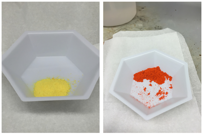
Collect the iridium photocatalyst 1a in an 89% yield (4.34 g) as a bright, yellow, crystalline solid (Fig. 9).
Figure 9 |.
Visual examples the two photocatalysts. Iridium photocatalyst 1a (left) and ruthenium photocatalyst 2a (right) are shown.
? TROUBLESHOOTING
■ PAUSE POINT Compound 1a can be stored in air at room temperature indefinitely. Photobleaching has been reported for iridium complexes of this type, so we recommend that these catalysts be stored in an amberized vial.
(B) Synthesis of photocatalyst 2a ● TIMING 48 h
In a one-neck, 500-ml round-bottom flask containing a Teflon-coated stir bar, weigh out 9.68 g of 2,2′-bipyridyl 62.0 mmol, 5.1 equiv.).
Add to the round-bottom flask 3.16 g of RuCl3●3H2O (12.1 mmol, 1.0 equiv.).
Equip the flask with a Liebig reflux condenser. Ensure that water is flowing at an appreciable rate through the condenser.
Seal the reflux condenser with a rubber septum and place the reaction mixture under vacuum for 1 min via an inlet needle.
Refill the flask with argon.
Perform four more such evacuation-backfill cycles, so that the flask and its contents are eventually under an argon atmosphere.
Add 300 ml of freshly distilled and degassed ethanol to the flask via a cannula.
Heat the solution to reflux (~80 °C) using an oil bath. Keep the solution refluxing for 16 h.
Remove the flask from the oil bath and let it cool to ~25 °C.
-
Remove the reflux condenser and add 16.30 g of NH4PF6 to the flask (100 mmol, 8.3 equiv.).
▲ CRITICAL STEP A voluminous brick-red precipitate should be observed at this time.
Place the flask back into the oil bath and heat it to 40 °C for 15 min.
Remove the flask from the oil bath and let it cool to room temperature. Subsequently chill the flask in a refrigerator (~5 °C) overnight (12–16 h).
Collect the solid by vacuum filtration through a Büchner fritted funnel.
Wash the solid thoroughly with H2O (~1 liter), ethanol (~300 ml), and finally with Et2O (~200 ml) to obtain the crude 2a.
Dissolve the red solid in boiling acetone (400 ml).
Filter the resulting red solution through a pad of Celite (10 × 3 cm) in a Büchner fritted funnel, into a 1-liter Büchner flask.
Wash the Celite with hot acetone (~300 ml).
Transfer the filtrate to a 2-liter round-bottom flask and concentrate the solution to about half of its original volume in vacuo by rotary evaporation (40 °C, 150 mmHg, ~15 min).
-
Add to the flask ~200 ml of HPLC-grade methanol and ~300 ml of Et2O.
▲ CRITICAL STEP The formation of a voluminous pumpkin-orange precipitate should be observed.
Collect the solid by vacuum filtration through a Büchner fritted funnel.
Wash the solid with EtOH (~300 ml) followed by Et2O (~200 ml).
Allow the solid to air-dry for 10 min.
Remove any remaining solvent by placing the solid in a 50-ml round-bottom flask and placing the flask under high vacuum (0.1 mmHg) for ~30 min.
Obtain the pure photocatalyst 2a in a 78% isolated yield (8.07 q; Fig. 9).
? TROUBLESHOOTING
■ PAUSE POINT 2a is indefinitely stable under atmospheric conditions at room temperature.
? TROUBLESHOOTING
Troubleshooting advice can be found in Table 2.
TABLE 2 |.
Troubleshooting table.
| Step | Problem | Possible reason | Solution |
|---|---|---|---|
| 1A(lvii), synthesis of 1a | Resulting solid is not yellow | Co-crystallization of acetone | The resultant crystals can contain some residual acetone, which, to the best of our knowledge, has a negligible effect on catalyst activity but will lead to a change in color (typically more orange or red). Residual acetone can be removed through azeotropic distillation in vacuo with CHCl3 (typically by dissolving the crude material in ~200 ml/g of photocatalyst) |
| Presence of nanoparticles | Dissolve the solid in the minimum amount possible of dry acetone. Add a few drops of pentane to the acetone to cause precipitation of the desired product, and then filter through a cotton-containing pipette. Remove the solvent | ||
| Obtained solid is sticky | Incomplete drying | Place the obtained solid in a small Buchner fritted funnel atop a small Buchner flask. Wash the solid with Et2O and then with pentane. Repeat Step 1A(liv-lvi) | |
| Yield is low (see ANTICIPATED RESULTS for expected yields) | Incomplete crystallizationa | Collect the organic solutions from Steps 1A(lii) and 1A(liii). Remove the solvent in vacuo. Dissolve the resulting solid in the minimum amount of acetone and place the resulting solution in a scintillation vial. Repeat Steps 1A(xlix-lvii) | |
| Loss of material during washes | Collect the organic solutions from Steps 1A(xlii, xliii, lii, and liii) and combine them. Remove the solvent in vacuo by rotary evaporation. Dissolve the resulting solid in the minimum amount of dichloromethane and, using an automated chromatographic machine, elute the desired product into test tubes through a prepacked silica column using a 95:5 (by volume) mixture of CH2Cl2/iPrOH. Transfer the fractions containing the product to a round-bottom flask and remove solvent from the eluate in vacuo by rotary evaporation (10 mmHg, 38 °C) to obtain pure 1a. | ||
| 1B(xxiv), synthesis of 2a | Resulting solid is not red | Traces of ruthenium(0) particles | Dissolve the solid using 400 ml of hot acetone and filter the solution through a 10 × 3 cm pad of Celite, eluting with an additional ~300 ml of hot acetone. Remove the acetone in vacuo by rotary evaporation (10 mmHg, 38 °C) |
| NMR analysis of 2a (see Analytical data in the ANTICIPATED RESULTS) shows the presence of other complexes | Incomplete anion metathesis | Dissolve the solid using ~200 ml of H2O, and add ~2 equiv. of NH4PF6 to the mixture. Sonicate the resulting suspension at room temperature for 30 min and then filter it. This procedure will afford a brick-red cake of the desired product. Proceed to dry the solid as defined in the PROCEDURE. | |
| Obtained solid is sticky | Incomplete drying | Place the solid in a separatory funnel and wash with diethyl ether (~150 ml) followed by pentane (~150 ml). Collect the solid and place it under high vacuum (< 1 mmHg while heating to ~50 °C) | |
| Yield is low (see ANTICIPATED RESULTS for expected yields) | Incomplete precipitation | Collect and combine the organic filtrates and remove the solvent in vacuo by rotary evaporation (10 mmHg, 38 °C). Take the crude solid up in acetone (200 ml) and, using the same precipitation method, repeat Steps 1B(xvi-xxiv) using a quarter of the solvent volumes listed. |
The procedures described in the second paragraph of the Solution column can be applied to address both possible reasons reported for low 1a yield.
● TIMING
Step 1A(i-xx), preparation of iridium dimer 4a: 48 h
Step 1A(xxi-lvii), conversion of the dimer to 1a: 72–96 h
Step 1B, synthesis of photocatalyst 2a: 48 h
Box 1, preparation of ligand 3a via a Suzuki cross-coupling: 24 h
Box 2, photoredox cross-coupling of a sterically hindered secondary alkyltrifluoroborate salt with a heteroaryl bromide: 24 h
Box 3, cross-coupling of 1° alkylsilicate with 1-bromonaphthalene via photoredox/nickel dual catalysis: 24 h
Box 4, conversion of 3-phenyl-l-propanol to 3-phenyl-l-bromopropane via photoredox catalysis: 24 h
Box 5, Giese-type reaction of benzyl trifluoroborate and methyl vinyl ketone via photoredox catalysis: 24 h
ANTICIPATED RESULTS
In general, the yields for the preparation of photocatalysts 1a and 2a are very good.
| Compound | Expected overall yield | Appearance | Melting point (°c) |
|---|---|---|---|
| [Ir{dF(CF3)ppy}2(bpy)]PF6, 1a | 55–65%a | See Figure 9 | 199–202 |
| [Ru(bpy)3](PF6)2, 2a | 70–80% | See Figure 9 | > 260 |
Yields on smaller-scale preparations (<3 mmol of IrCl3) are generally higher (75–85%).
Analytical data
[I{dF(CF3)ppy}2(bpy)]PF6, 1a. 1H NMR (acetone-d6, 500 MHz) δ 6.00 (dd, J = 8.4, 2.1 Hz, 2H), 6.83–6.96 (m, 2H), 7.84 (t, J = 6.4 Hz, 2H), 8.01 (s, 2H) 8.35 (d, J = 4.9 Hz, 2H), 8.41–8.47 (m, 4H), 8.66 (d, J = 10.3 Hz, 2H), 8.94 (d, J = 8.3 Hz, 2H)
13C NMR (acetone-d6, 125 MHz) δ 99.3 (t, J = 26.6 Hz, CH), 114.4 (dd, J = 17.9, 3.2 Hz, CH), 122.0 (q, J = 272.2 Hz, CF3), 123.8 (d, J = 21.1 Hz, CH), 125.3 (CH), 125.3 (q, J = 34.8 Hz, C), 126.8 (q, J = 1.8 Hz, C), 129.1 (CH), 137.2 (q, J = 2.8 Hz, CH), 140.6 (CH), 146.1 (q, J = 4.6 Hz, CH), 151.4 (CH), 155.1 (d, J = 6.4 Hz, C), 155.9 (C), 162.4 (dd, J = 266.7, 12.8 Hz, CF), 164.4 (dd, J = 263.0, 13.7 Hz, CF), 167.6 (d, J = 7.3 Hz, C)
19F NMR (acetone-d6, 471 MHz) δ −108.25 (d, J = 12.21 Hz, 2F), −105.00 (d, J = 12.21 Hz, 2F), −73.69 (m, 3F), −72.19 (s, 3F), −63.85 (s, 6F)
31P NMR (acetone-d6, 202 MHz) δ−144.27 (quin, J = 707.10 Hz)
[Ru(bpy)3](PF6)2, 2a. 1H NMR (acetone-d6, 500 MHz) δ 7.57–7.66 (m, 6H), 8.10 (dd, J = 5.6, 0.5 Hz, 6H), 8.25 (tt, J = 7.8, 1.2 Hz, 6H), 8.86 (dd, J = 8.2, 0.6 Hz, 6H)
13C NMR (acetone-d6, 125 MHz) 5125.0 (CH), 128.5 (CH), 138.6 (CH), 152.4 (CH), 157.8 (C)
19F NMR (acetone-d6, 471 MHz) −73.58 (s, 6F) −72.08 (s, 6F)
31P NMR (acetone-d6, 202 MHz) −144.27 (quin, J = 704.60 Hz)
ACKNOWLEDGMENTS
The authors are grateful for the financial support provided by the National Institute of General Medical Sciences (RO1 GM111465, R01-GM-113878), the National Science Foundation (CHE-1362841), Pfizer, and Eli LilLy. C.B.K. is grateful for a National Institutes of Health National Research Service Award postdoctoral fellowship (F32GM117634–01). J.C.T. is grateful for fellowship support from Bristol-Myers Squibb. In addition, the authors thank Sigma-Aldrich for the generous material donation of iridium(III) chloride and Johnson Matthey for the donations of iridium(III) chloride and ruthenium(III) chloride trihydrate.
Footnotes
COMPETING FINANCIAL INTERESTS The authors declare no competing financial interests.
References
- 1.Douglas JJ, Nguyen JD, Cole KP & Stephenson CRJ Enabling novel photoredox reactivity via photocatalyst selection. Aldnchim. Acta 47, 15–25 (2014). [Google Scholar]
- 2.Koike T & Akita M Visible-light radical reaction designed by Ru- and Ir-based photoredox catalysis. Inorg. Chem. Front 1, 562–576 (2014). [Google Scholar]
- 3.Prier CK, Rankic DA & MacMillan DWC Visible light photoredox catalysis with transition metal complexes: applications in organic synthesis. Chem. Rev 113, 5322–5363 (2013). [DOI] [PMC free article] [PubMed] [Google Scholar]
- 4.Fukuzumi S & Ohkubo K Selective photo catalytic reactions with organic photocatalysts. Chem. Sei 4, 561–574 (2013). [Google Scholar]
- 5.Xi Y, Yi H & Lei A Synthetic applications of photoredox catalysis with visible light. Org. BiomoL Chem 11, 2387–2403 (2013). [DOI] [PubMed] [Google Scholar]
- 6.Tucker JW & Stephenson CRJ Shining Light on photoredox catalysis: theory and synthetic applications. J. Org. Chem 77, 1617–1622 (2012). [DOI] [PubMed] [Google Scholar]
- 7.Studer A & Curran DP Catalysis of radical reactions: a radical chemistry perspective. Angew. Chem. Int. Ed 55, 58–102 (2016). [DOI] [PubMed] [Google Scholar]
- 8.Juris A et al. Ru(II) polypyridine complexes: photophysics, photochemistry, electrochemistry, and chemiLuminescence. Coord. Chem. Rev 84, 85–277 (1988). [Google Scholar]
- 9.Duret G, QuinLan R, Bisseret P & BLanchard N Boron chemistry in a new light. Chem. Sei 6, 5366–5382 (2015). [DOI] [PMC free article] [PubMed] [Google Scholar]
- 10.Hanss D, Freys JC, Bernardinelli G & Wenger OS Cyclometalated iridium(III) complexes as photosensitizers for Long-range electron transfer: occurrence of a coulomb barrier. Eur. J. Inorg. Chem 2009, 4850–4859 (2009). [Google Scholar]
- 11.Lowry MS et al. SingLe-layer electroluminescent devices and photoinduced hydrogen production from an ionic iridium(III) complex. Chem. Mater 17, 5712–5719 (2005). [Google Scholar]
- 12.Tamayo AB et al. Synthesis and characterization of facial and meridional tris-cyclometalated iridium(III) complexes. J. Am. Chem. Soc 125, 7377–7387 (2003). [DOI] [PubMed] [Google Scholar]
- 13.Hopkinson MN, Sahoo B, Li J-L & Glorius F Dual catalysis sees the light: combining photoredox with organo-, acid, and transition-metal catalysis. Chemistry 20, 3874–3886 (2014). [DOI] [PubMed] [Google Scholar]
- 14.Skubi KL, BLum TR & Yoon TP Dual catalysis-strategies in photochemical synthesis. Chem. Rev 116, 10035–10074 (2016). [DOI] [PMC free article] [PubMed] [Google Scholar]
- 15.Levin MD, Kim S & Toste FD Photoredox catalysis unlocks single-electron elementary steps in transition metal catalyzed cross-coupling. ACS Cent. Sei 2, 293–301 (2016). [DOI] [PMC free article] [PubMed] [Google Scholar]
- 16.Gui Y-Y, Sun L, Lu Z-P & Yu D-G Photoredox sheds new light on nickel catalysis: from carbon-carbon to carbon-heteroatom bond formation. Org. Chem. Front 3, 522–526 (2016). [Google Scholar]
- 17.Tellis JC, Primer DN & Molander GA Single-electron transmétalation in organoboron cross-coupling by photoredox/nickel dual catalysis. Science 345, 433–436 (2014). [DOI] [PMC free article] [PubMed] [Google Scholar]
- 18.Primer DN, Karakaya I, Tellis JC & Molander GA Single-electron transmétalation: an enabling technology for secondary alkylboron cross-coupling. J. Am. Chem. Soc 137, 2195–2198 (2015). [DOI] [PMC free article] [PubMed] [Google Scholar]
- 19.Gutierrez 0, Tellis JC, Primer DN, Molander GA & Kozlowski MC Nickel-catalyzed cross-coupling of photoredox-generated radicals: uncovering a general manifold for stereoconvergence in niekel-catalyzed cross-couplings. J. Am. Chem. Soc 137, 4896–4899 (2015). [DOI] [PMC free article] [PubMed] [Google Scholar]
- 20.Yamashita Y, Tellis JC & Molander GA rotecting group-free, selective cross-coupling of alkyltrifluoroborates with borylated aryl bromides via photoredox/nickel dual catalysis. Proc. Natl. Acad. Sei. USA 112, 12026–12029 (2015). [DOI] [PMC free article] [PubMed] [Google Scholar]
- 21.Karakaya I, Primer DN & Molander GA Photoredox cross-coupling: Ir/Ni dual catalysis for the synthesis of benzylic ethers. Org. Lett 17, 3294–3297 (2015). [DOI] [PMC free article] [PubMed] [Google Scholar]
- 22.El Khatib M, Serafim RAM & Molander GA α-Arylation/heteroarylation of chiral α-aminomethyltrifluoroborates by synergistic iridium photoredox/nickel cross-coupling catalysis. Angew. Chem. Int. Ed 55, 254–258 (2016). [DOI] [PMC free article] [PubMed] [Google Scholar]
- 23.Amani J, Sodagar E & Molander GA Visible light photoredox cross-coupling of acyl chlorides with potassium alkoxymethyltrifluoroborates: synthesis of α-alkoxyketones. Org. Lett 18, 732–735 (2016). [DOI] [PMC free article] [PubMed] [Google Scholar]
- 24.Zuo ZW et al. Merging photoredox with nickel catalysis: coupling of α-carboxyl sp3-carbons with aryl halides. Science 345, 437–440 (2014). [DOI] [PMC free article] [PubMed] [Google Scholar]
- 25.Chu L, Lipshultz JM & MacMillan DWC Merging photoredox and nickel catalysis: the direct synthesis of ketones by the decarboxylative arylation of α-oxo acids. Angew. Chem. Int. Ed 54, 7929–7933 (2015). [DOI] [PMC free article] [PubMed] [Google Scholar]
- 26.Le CC & MacMillan DWC Fragment couplings via CO2 extrusion-recombination: expansion of a classic bond-forming strategy via metallaphotoredox. J. Am. Chem. Soc 137, 11938–11941 (2015). [DOI] [PMC free article] [PubMed] [Google Scholar]
- 27.Noble A, McCarver SJ & MacMillan DWC Merging photoredox and nickel catalysis: decarboxylative cross-coupling of carboxylic acids with vinyl halides. J. Am. Chem. Soc 137, 624–627 (2015). [DOI] [PMC free article] [PubMed] [Google Scholar]
- 28.Terrett JA, Cuthbertson JD, Shurtleff VW & MacMillan DWC Switching on elusive organometallic mechanisms with photoredox catalysis. Nature 524, 330–334 (2015). [DOI] [PMC free article] [PubMed] [Google Scholar]
- 29.Shaw MH, Shurtleff VW, Terrett JA, Cuthbertson JD & MacMillan DWC Native functionality in triple catalytic cross-coupling: sp3 C-H bonds as latent nucleophiles. Science 352, 1304–1308 (2016). [DOI] [PMC free article] [PubMed] [Google Scholar]
- 30.Kalyani D, McMurtrey KB, Neufeldt SR & Sanford MS Room-temperature C-H arylation: merger of Pd-catalyzed C-H functionalization and visible-light photo catalysis. J. Am. Chem. Soc 133, 18566–18569 (2011). [DOI] [PMC free article] [PubMed] [Google Scholar]
- 31.Ye Y & Sanford MS Merging visible-light photo catalysis and transition-metal catalysis in the cop per-catalyzed trifluoromethylation of boronic acids with CF3I. J. Am. Chem. Soc 134, 9034–9037 (2012). [DOI] [PMC free article] [PubMed] [Google Scholar]
- 32.Neufeldt SR & Sanford MS Combining transition metal catalysis with radical chemistry: dramatic acceleration of palladium-catalyzed C-H arylation with diaryliodonium salts. Adv. Synth. Catal 354, 3517–3522 (2012). [DOI] [PMC free article] [PubMed] [Google Scholar]
- 33.Jouffroy M, Primer DN & Molander GA Base-free photoredox/nickel dual-catalytic cross-coupling of ammonium alkylsilicates. J. Am. Chem. Soc 138, 475–478 (2016). [DOI] [PMC free article] [PubMed] [Google Scholar]
- 34.Corcé V et al. Silicates as latent alkyl radical precursors: visible-light photo catalytic oxidation of hypervalent bis-catecholato silicon compounds. Angew. Chem. Int. Ed 54, 11414–11418 (2015). [DOI] [PubMed] [Google Scholar]
- 35.Patel NR, Kelly CB, Jouffroy M & Molander GA Engaging alkenyl halides with alkylsilicates via photoredox dual catalysis. Org. Lett 18, 764–767 (2016). [DOI] [PMC free article] [PubMed] [Google Scholar]
- 36.Jouffroy M, Davies GHM & Molander GA Accessing elaborated 2,1-borazaronaphthalene cores using photoredox/nickel dual-catalytic functionalization. Org. Lett 18, 1606–1609 (2016). [DOI] [PMC free article] [PubMed] [Google Scholar]
- 37.Lévêque C, Chenneberg L, Corcé V, Goddard J-P & Ollivier C et al. Primary alkyl bis-catecholato silicates in dual photoredox/nickel catalysis: aryl- and heteroaryl-alkyl cross coupling reactions. Org. Chem. Front 3, 462–465 (2016). [Google Scholar]
- 38.Kim S, Rojas-Martinab J & Toste FD Visible light-mediated gold-catalysed carbon(sp2)-carbon(sp) cross-coupling. Chem. Sei 7, 85–88 (2016). [DOI] [PMC free article] [PubMed] [Google Scholar]
- 39.Shu XZ, Zhang M, He Y, Frei H & Toste FD Dual visible light photoredox and gold-catalyzed arylative ring expansion. J. Am. Chem. Soc 136, 5844–5847 (2014). [DOI] [PMC free article] [PubMed] [Google Scholar]
- 40.He Y, Wuab H & Toste FD A dual catalytic strategy for carbon-phosphorus cross-coupling via gold and photoredox catalysis. Chem. Sei 6, 1194–1198 (2015). [DOI] [PMC free article] [PubMed] [Google Scholar]
- 41.Sahoo B, Hopkinson MN & Glorius F Combining gold and photoredox catalysis: visible light-mediated oxy- and aminoarylation of alkenes. J. Am. Chem. Soc 135, 5505–5508 (2013). [DOI] [PubMed] [Google Scholar]
- 42.Hopkinson MN, Sahoo B & Glorius F Dual photoredox and gold catalysis: intermolecular multicomponent oxyarylation of alkenes. Adv. Synth. Catal 356, 2794–2800 (2014). [Google Scholar]
- 43.Rueping M, Koenigs RM, Poscharny K, Fabry DC, Leonori D & Vila C Dual catalysis: combination of photo catalytic aerobic oxidation and metal catalyzed alkynylation reactions—C-C bond formation using visible light. Chemistry 18, 5170–5174 (2012). [DOI] [PubMed] [Google Scholar]
- 44.Tasker SZ & Jamison TF Highly regioselective indoline synthesis under nickel/photo redox dual catalysis. J. Am. Chem. Soc 137, 9531–9534 (2015). [DOI] [PMC free article] [PubMed] [Google Scholar]
- 45.Xuan J, Zeng T-T, Chen J-T, Lu L-Q & Xiao WJ Room temperature C-P bond formation enabled by merging nickel catalysis and visible-light-induced photoredox catalysis. Chemistry 21, 4962–4965 (2015). [DOI] [PubMed] [Google Scholar]
- 46.Cheng W-M, Shang R, Yu H-Z & Fu Y Room-temperature decarboxyLative couplings of a-oxocarboxylates with aryl halides by merging photoredox with palladium catalysis. Chemistry 21, 13191–13195 (2015). [DOI] [PubMed] [Google Scholar]
- 47.Jouffroy M, Kelly CB & Molander GA Thioetherification via photoredox/nickel dual catalysis. Org. Lett 18, 876–879 (2016). [DOI] [PMC free article] [PubMed] [Google Scholar]
- 48.Oderinde MS, Frenette M, Robbins DW, Aquila B & Johannes JW Photoredox mediated nickel catalyzed cross-coupling of thiols with aryl and heteroaryl iodides via thiyl radicals. J. Am. Chem. Soc 138, 1760–1763 (2016). [DOI] [PubMed] [Google Scholar]
- 49.Lang SB, 0’Nele KM & Tunge JA DecarboxyLative allylation of amino alkanoic acids and esters via dual catalysis. J. Am. Chem. Soc 136, 13606–13609 (2014). [DOI] [PMC free article] [PubMed] [Google Scholar]
- 50.Lang SB, O’Nele KM, DougLas JT & Tunge JA DuaL catalytic decarboxyLative allylations of a-amino acids and their divergent mechanisms. Chemistry 21, 18589–18593 (2015). [DOI] [PMC free article] [PubMed] [Google Scholar]
- 51.Singh A, Teegardin K, Kelly M, Prasad KS, Krishnan S & Weaver JD Facile synthesis and complete characterization of homoleptic and heteroleptic cyclometalated iridium(III) complexes for photocatalysis. J. Organomet. Chem 776, 51–59 (2015). [Google Scholar]
- 52.Dai C, Narayanam JMR & Stephenson CRJ Visible-light-mediated conversion of alcohols to halides. Nat. Chem 3, 140–145 (2011). [DOI] [PubMed] [Google Scholar]
- 53.Yasu Y, Koike T & Akita M Visible light-induced selective generation of radicals from organoborates by photoredox catalysis. Adv. Synth. CataL 354, 3414–3420 (2012). [Google Scholar]


