Abstract
In this study, we aim to create and validate a Finite Element (FE) model to estimate the bone temperature after cement injection and compare the simulation temperature results with experimental data in three key locations of the proximal femur. Simulation results suggest that the maximum temperature-rise measured at the bone surface is 10°C which occurs about 12 minutes after the injection. Temperature profiles measured during the experiment showed an agreement with those of the simulation with an average error of 1.73°C Although additional experiments are required to further validate the model, results of this study suggest that this model is a promising tool for bone augmentation planning to lower the risk of thermal necrosis.
INTRODUCTION
One-year mortality rate after osteoporotic hip fracture in elderly is 23% [1]. Current preventive measures commonly do not have a short term (less than one year) effect. Moreover, the risk of a second hip fracture increases 6–10 times in elderly with osteoporosis [2]. Osteoporotic hip augmentation (femoroplasty) is a possible preventive approach for patients at the highest risk of fracture and who cannot tolerate other treatment modalities [3–5]. Recent computational work and cadaveric studies have demonstrated that osteoporotic hip augmentation with Polymethylmethacrylate (PMMA) can significantly improve yield load and fracture energy [6, 7]. However, higher volumes of PMMA injection may introduce the risk of thermal necrosis. Prior studies have pointed out that the temperatures in the range of 45°C to 60°C may cause thermal tissue damage, depending on the exposure time [9, 10]. Therefore, in addition to the mechanical strength of the femur, maximum temperature-rise and duration of thermal exposure are important factors that needs to be considered while planning the injection parameters for femoroplasty.
Some researchers have developed simulation models to study the temperature distribution after cementation with PMMA both in 2D and 3D, most of which have considered cement and bone as homogenous continuum materials and the bone-cement-interface is often characterized by its conductivity [11, 12]. Baliga et al., presented a methodology for numerical simulation of unsteady heat conduction in PMMA during its polymerization and demonstrated an agreement between the numerical predictions and the corresponding experimental results. Hansen et al. proposed a general model for acrylic cementation in hip-joint-replacement surgery based on the principles of polymerization kinetics and heat transfer [12]. The validity and capabilities of such methods has inspired us to consider heat transfer modeling as a potential approach for evaluating temperature rise during cementation, thereby lowering the risks associated with femoroplasty. In this paper, we present 3D heat transfer simulations for temperature evaluation during femoroplasty. In addition, we aim to validate these models through direct measurements of the bone surface temperature in experiments where bone injection profiles are customized based on the method of bi-directional Evolutionary Structural Optimization (BESO).
METHODS
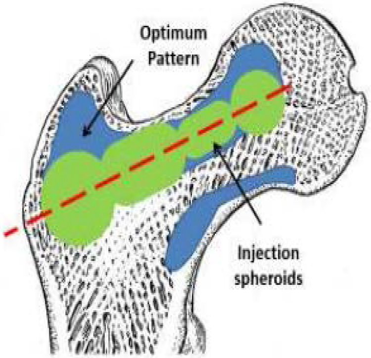
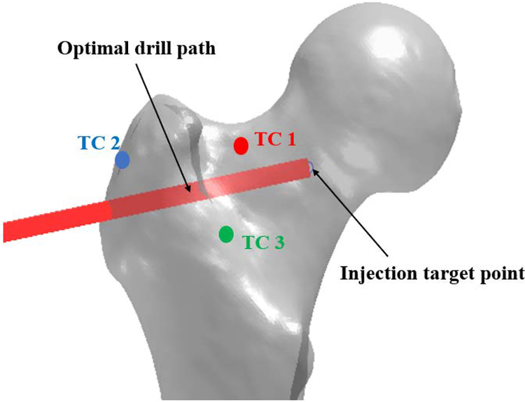
Computed Tomography (CT) scans of two osteoporotic cadaver femur specimens with neck t-scores of −3.2 and −2.7 were obtained. The optimized cement distribution profile for augmentation of these specimens were determined using a modified method of BESO described in [6]. The goal of BESO was to find minimum volume of cement that increases the predicted yield load of the specimen. In the second step, the FE-optimized injection pattern was approximated by number of spheroids (realistic injection volumes) along a single injection path as shown in Fig 3. During this step the size and location of the spheroids was optimized to find the best match between FE model and the spheroid alignments. Fig. 4 shows the resulting drill path for cementation.
Fig 3.
Schematic of the optimized injection pattern by BESO (blue), practical injection volume (green) and line of injection (red) [14]
Fig 4.
Optimal drill path and thermocouple placements on the femoral bone surface
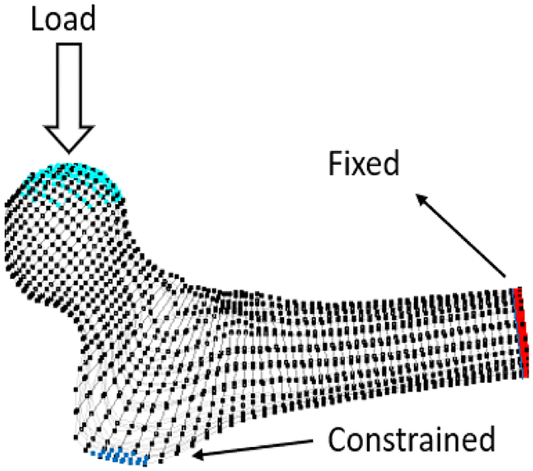
To ensure the efficacy of the planned injection, we used a particle-based simulation described in [13] to predict the resulting pattern of cement diffusion inside the bone and estimated the biomechanical effects of cementation on sideway falls on the greater trochanter (Fig. 1).
Fig 1.
Boundary conditions
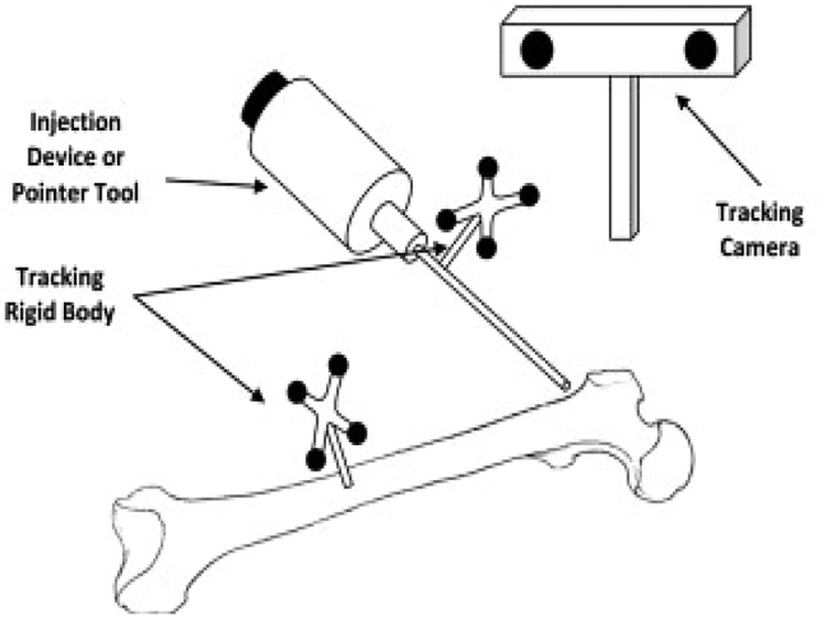
To accurately inject PMMA in selected regions of the bone, we used a previously developed navigation system along with a custom-made injection device [7, 15–16]. We used a cordless hand drill (DCD760, DeWalt Industrial Tool Co., Baltimore, MD) with a custom attachment for mounting the tracking rigid body, and the navigation system to drill the injection path (Fig. 2). The navigation system visually guides the user to the desired location for drilling while providing real-time feedback of the distance and angle errors of drill placement.
Figure 2.
Injection System [7]
Once the bone was drilled based on the planning steps described, we proceeded to cement preparation: 15 g of radiopaque Spineplex (Stryker Instruments, Mahwah, NJ) bone cement powder was mixed with 13.5 ml of the monomer liquid for about 75 seconds. A 20 ml syringe was then filled with the cement and a 15 cm, 8G cannula (Scientific Commodities Inc., Lake Havasu, AZ) was attached to the syringe and mounted in a custom designed injection device [15]. After removing the air, the injection system was moved to the target point until the cement reached the target viscosity of 200 Pa s (usually within 12–15 minutes of mixing the powder with liquid). At this point, cementation started at the constant rate of 0.1 ml/s from the injection target point towards the drill entry point on the bone surface. Meanwhile, temperature-rise of the bone surface was directly measured via K-type thermocouples at femoral neck (TC 1), greater trochanter (TC 2) and Introchanteric line (TC 3). Fig. 4 shows the relative location of thermocouples to the selected injection path. Planning and injection procedures were repeated for the second femur specimen.
Following each injection experiment, another set of CT scans of the proximal femur were obtained. These scans were used to segment the injected PMMA along with bone surface in an open-source software MITK (German Cancer Research Center, Heidelberg, Germany). Next, an FE heat transfer model was created to estimate the bone surface temperature at every one second interval following cement injection in COMSOL Multiphysics, Inc (Burlington, MA). For this purpose, we assumed a homogenous material property inside the bone and a uniform heat flow from the bone-cement-interface towards the cortical bone surface. Table 1 shows the summery of material properties used for the simulation.
Table 1-.
Estimated material properties of the bone in FE model
| Property | Value | Unit |
|---|---|---|
| Thermal Conductivity (k) | 0.6 | W/m.K |
| Density (p) | 1000 | Kg/m3 |
| Heat Capacity at constant pressure (Cp) | 2200 | J/(kg.K) |
PMMA curing temperature profile at the bone-cement-interface was directly measured in a 130 mm by 45 mm by 40 mm open cell block (7.5 PCF) (Sawbone Inc., Vashon Island, WA), resembling human cancellous bone where 30 cm3 of canola oil was added to the block mimicking the bone marrow. This data was later used in simulations to estimate the bone surface temperature.
RESULTS
From planning, it was determined that 7.7 cm3 of PMMA is sufficient to increase the yield load of the first specimen by 67% (from 1350 N to 2256 N). For the second specimen, 9.1 cm3 of PMMA results in 105% of yield load increase (from 1170 N to 2395 N). Planning suggested that the yield energy of these specimens will increase by 161% and 116% respectively.
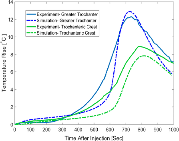
Temperature measurements for the first specimen indicated that greater trochanter’s temperature rises about 10°C after about 12 minutes since the start of injection. Maximum temperature-rise at the femoral neck and trochanteric crest were 7.1°C and 5.9°C respectively. Temperature profiles of this specimen were estimated in the FE simulation with an average error of 1.87°C at the Trochanteric crest, 1.23°C at the greater trochanter and 2.1°C at the femoral neck. To further validate the model, we compared the temperature measurements of the second specimen with those of FE simulations. As shown in Fig. 6, temperature of the second specimen at the greater trochanter
Fig 6.
Surface Temperature-rise of the Second femur specimen for the first 1000 seconds after the injection-Experimental results vs. predicted values
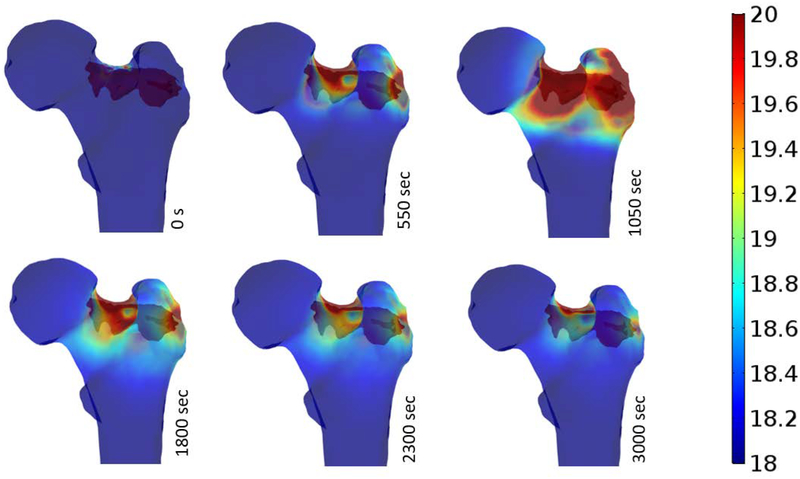
Temperature distributions of the bone surface after injection are estimated at different time intervals (time after injection) and illustrated in Fig. 7. As shown below, most of critical temperature-rises occurs at the superior and inferior aspects of the neck as well as supero-posterior aspect of the greater trochanter. Maximum temperatures of bone surface at different time intervals following the injection were extracted from simulations and are shown in Table 2.
Fig 7.
Surface temperature-rise of the femur during PMMA Polymerization.
Table 2.
Maximum temperature-rise of the bone at discrete time-intervals following PMMA injection
| Maximum Temperature Rise (°C) | ||
|---|---|---|
| Time (s) | Specimen 1 | Specimen 2 |
| 0 | 4.34 | 4.08 |
| 550 | 25.75 | 25.75 |
| 1050 | 29.67 | 29.15 |
| 1800 | 12.51 | 12.47 |
| 2300 | 9.09 | 9.07 |
| 3000 | 6.34 | 6.32 |
DISCUTION
Results of this study supports the findings of previous studies that femoroplasty can significantly increase the yield load and yield energy of the proximal femur even when a relatively small amount of PMMA bone cement is injected (less than 10 cm3). Our preliminary experiments of two femur specimens indicate that lower volume of PMMA may reduce the risk of thermal necrosis. For the first specimen where 7.6 cm3 of bone cement was injected, the maximum temperature-rise is 10°C which occurs at about 780 seconds after the injection. The exposure time for this rise is less than 30 seconds which is well below the levels causing thermal necrosis [17, 18]. In the second injection experiment, greater trochanter of the femur was exposed to temperatures above 10°C for over 200 seconds. Therefore, the thermal necrosis can be expected for these injection scenarios which confirm the potential need of cooling technique during cementation.
For heat transfer model, we have assumed a homogenous material property for the bone tissue. The parameters shown in table 1 were estimated and modified based on the direct temperature measurements of the bone surface. In order to validate the simulation results, we compared the temperature measurements on the surface of second femur with corresponding temperatures from FE simulation without further modifications of the material properties (Fig. 6).
One of the limitations of the In-vitro experiments presented in this study was the base-temperature of the bone tissue during the injection (about 22°C) that is well below the 37°C body temperature. In addition, lack of blood flow in cadaver specimens may result in an increased temperature-rise during PMMA curing. Previous studies pointed out that thermal necrosis is expected when tissue is exposed to more than 60°C [19]. Therefore, with the temperature-rise values shown in Table 2, both injection scenarios may result in tissue damage.
Among other limitations of this study was the technique used to fix the thermocouple on the bone surface prior to each injection experiments. Points of measurements were randomly selected in the regions of interest and localized through X-ray images of the bone. Therefore, the verification of the location of the maximum temperature in the bone, as determined by simulation, was not possible.
In conclusion, we have developed an FE model capable of estimating the bone surface temperature based on a given pattern of injection. This model is validated through direct measurements via K-type thermocouples and can be utilized to avoid injection scenarios that may result in thermal necrosis. Future works include integration of this model into the planning paradigm to lower the risk of tissue damage. In addition, PMMA injection can be combined with bone cooling techniques that assists in lowering bone temperature without interfering with cement’s polymerization, thereby reducing the risk of thermal necrosis.
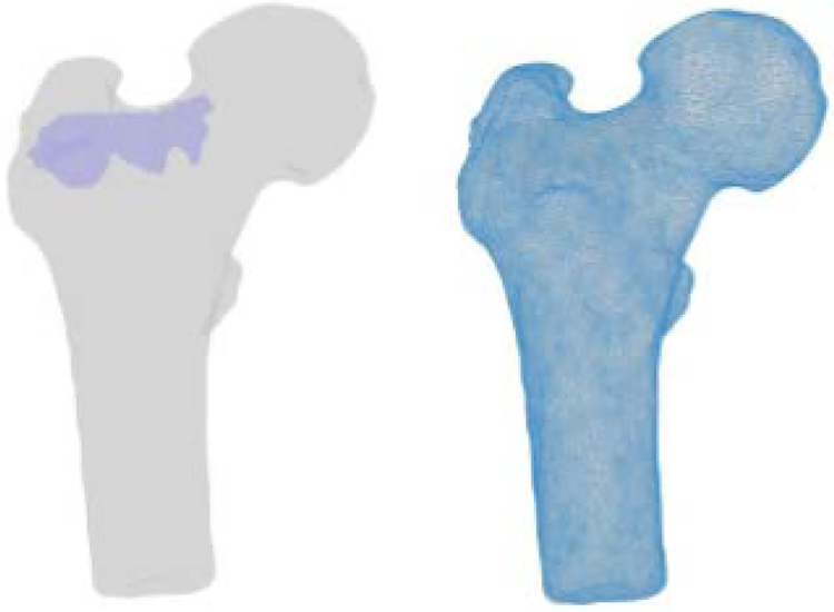
Fig 5.
Segmented geometries of the bone and PMMA (left) FE mesh of the bone geometry (right)
ACKNOWLEDGMENTS
Research reported in this publication was supported by the National Institute of Arthritis and Musculoskeletal and Skin Diseases of the National Institutes of Health under Award Number R21AR06315 and R01EB023939. The content is solely the responsibility of the authors and does not necessarily represent the official views of the National Institutes of Health.
Contributor Information
Amirhossein Farvardin, Laboratory for Computational Sensing & Robotics, Department of Mechanical Engineering, Johns Hopkins University, Baltimore, Maryland, United States.
Mahsan Bakhtiari Nejad, Laboratory for Computational Sensing & Robotics, Department of Mechanical Engineering, Johns Hopkins University, Baltimore, MD, United States.
Michael Pozin, Department of Mechanical Engineering, Johns Hopkins University, Baltimore, Maryland, United States.
Mehran Armand, Laboratory for Computational Sensing & Robotics, Department of Mechanical Engineering, Johns Hopkins University, Johns Hopkins University Applied Physics, Laboratory, Laurel, Maryland, United States.
REFERENCES
- [1].Cummings SR, Rubin SM and Black D, 1990. The future of hip fractures in the United States. Numbers, costs, and potential effects of postmenopausal estrogen. Clinical orthopaedics and related research, (252), pp.163–166. [PubMed] [Google Scholar]
- [2].Dinah AF, 2002. Sequential hip fractures in elderly patients. Injury, 33(5), pp.393–394. [DOI] [PubMed] [Google Scholar]
- [3].Sutter EG, Mears SC, and Belkoff SM, 2010. “A biomechanical evaluation of femoroplasty under simulated fall conditions”. Journal of Orthopaedic Trauma, 24(2), pp. 95–99. [DOI] [PMC free article] [PubMed] [Google Scholar]
- [4].Heini PF, Franz T, Fankhauser C, Gasser B, and Ganz R, 2004. “Femoroplasty-augmentation of mechanical properties in the osteoporotic proximal femur: a biomechanical investigation of pmma reinforcement in cadaver bones”. Clinical Biomechanics, 19, pp. 506–512. [DOI] [PubMed] [Google Scholar]
- [5].Beckmann J, Ferguson S, Gebauer M, Luering C, Gasser B, and Heini P, 2007. “Femoroplasty augmentation of the proximal femur with a composite bone cement feasibility, biomechanical properties and osteosynthesis potential”. Medical Engineering & Physics, 29, pp. 755–764. [DOI] [PubMed] [Google Scholar]
- [6].Basafa E, Armiger RS, Kutzer MD, Belkoff SM, Mears SC and Armand M, 2013. Patient-specific finite element modeling for femoral bone augmentation. Medical Engineering and Physics, 35(6), pp.860–865. [DOI] [PMC free article] [PubMed] [Google Scholar]
- [7].Basafa E, Murphy RJ, Otake Y, Kutzer MD, Belkoff SM, Mears SC and Armand M, 2015. Subject-specific planning of femoroplasty: an experimental verification study. Journal of biomechanics, 48(1), pp.59–64. [DOI] [PMC free article] [PubMed] [Google Scholar]
- [8].Huiskes R, 1980. Some fundamental aspects of human joint replacement: analyses of stresses and heat conduction in bone-prosthesis structures. Acta Orthopaedica Scandinavica, 51(sup185), pp.3–208. [PubMed] [Google Scholar]
- [9].Diller KR, 1985. Analysis of skin burns In Heat transfer in medicine and biology (pp. 85–134). Springer, Boston, MA. [Google Scholar]
- [10].Buettner K, 1951. Effects of extreme heat and cold on human skin. II. Surface temperature, pain and heat conductivity in experiments with radiant heat. Journal of Applied Physiology, 3(12), pp.703–713. [DOI] [PubMed] [Google Scholar]
- [11].Baliga BR, Rose PL and Ahmed AM, 1992. Thermal modeling of polymerizing polymethylmethacrylate, considering temperature-dependent heat generation. Journal of Biomechanical Engineering, 114(2), pp.251–259. [DOI] [PubMed] [Google Scholar]
- [12].Hansen E, 2003. Modelling heat transfer in a bone–cement–prosthesis system. Journal of biomechanics, 36(6), pp.787–795. [DOI] [PubMed] [Google Scholar]
- [13].Basafa E, Murphy RJ, Kutzer MD, Otake Y and Armand M, 2013. A particle model for prediction of cement infiltration of cancellous bone in osteoporotic bone augmentation. PloS one, 8(6), p. e 67958. [DOI] [PMC free article] [PubMed] [Google Scholar]
- [14].Farvardin A, Basafa E and Armand M, A NOVEL PLANNING PARADIGM FOR AUGMENTATION OF OSTEOPOROTIC FEMUR. [Google Scholar]
- [15].Otake Y, Armand M, Armiger RS, Kutzer MD, Basafa E, Kazanzides P and Taylor RH, 2012. Intraoperative image-based multiview 2D/3D registration for image-guided orthopaedic surgery: incorporation of fiducial-based C-arm tracking and GPU-acceleration. IEEE transactions on medical imaging, 31(4), pp.948–962. [DOI] [PMC free article] [PubMed] [Google Scholar]
- [16].Kutzer MD, Basafa E, Otake Y and Armand M, 2011, January An automatic injection device for precise cement delivery during osteoporotic bone augmentation In ASME 2011 International Design Engineering Technical Conferences and Computers and Information in Engineering Conference(pp. 821–827). American Society of Mechanical Engineers. [Google Scholar]
- [17].Li S, Chien S and Brånemark PI, 1999. Heat shock-induced necrosis and apoptosis in osteoblasts. Journal of orthopaedic research, 17(6), pp.891–899. [DOI] [PubMed] [Google Scholar]
- [18].Eriksson AR and Albrektsson T, 1983. Temperature threshold levels for heat-induced bone tissue injury: a vital-microscopic study in the rabbit. Journal of prosthetic dentistry, 50(1), pp.101–107. [DOI] [PubMed] [Google Scholar]


