Abstract
Wireless magnetoelastic sensors offer significant potential for measuring the accumulation of biomass within stents – enabling early detection prior to stent occlusion – but the encapsulation of these sensors remains a critical challenge. The encapsulation must allow the sensors to navigate the curvature and accommodate the contact forces imparted during and after the implantation procedure, while also leaving the sensor open to mechanical interaction with the biomass during the extended period of deployment. This paper is focused on the encapsulation of ribbon-like magnetoelastic sensors (12.5 mm × 1 mm × 60 μm) within plastic biliary stents (inner diameter of 2.54 mm). The compromise between two polymer-based package designs – one mechanically flexible (Type F) and one mechanically stiff (Type S) – is evaluated. The primary advantage of the Type F package is the flexibility during the delivery process while that of the Type S package is in maintaining a strong signal even when the stent is in a curved bile duct. The maximum thicknesses of the Type F and S packages are 0.53 mm and 0.74 mm, respectively. Mechanical tests show that both types protect the sensors from forces imparted by a standard introducer, and allow the encapsulated sensors to accommodate bending with a radius of curvature as small as 3 cm. The Type F package has also been tested in situ, in the bile duct of a porcine carcass. The signal is measurable with a wireless range of ≈10 cm, at a resonant frequency of 159 kHz and a quality factor of 397.
Keywords: Biliary sludge, implant, mass and viscosity sensing, packaging, resonant sensors, 3D printing
I. INTRODUCTION
STENTS are widely used to maintain patency of a constricted vessel or duct, but it is often necessary to monitor the effectiveness of the stents because accumulation of tissue and/or other biomass may lead to restenosis over varying periods of time [1–7]. Current practices for monitoring stent blockage – such as blood tests, magnetic resonance imaging, or angiography/cholangiography – are either indirect, invasive, or expensive [8, 9]. These shortcomings often lead to mistimed therapeutic actions: a preemptive and unnecessary invasive procedure, or post-symptomatic stent replacement with elevated risk of blood poisoning or other fatal conditions.
Our previous work [10–12] has demonstrated – with benchtop and in situ results – the use of wireless magnetoelastic sensors to directly measure the accumulation of biomass within stents. The strong magnetoelastic properties of the sensors results from tight coupling between stress, strain, and magnetism in the sensor material [13], When exposed to a time-varying magnetic field, the magnetic domains in a magnetoelastic material tend to rotate and align with the changing field, straining the material and causing mechanical vibrations. These vibrations generate another oscillating magnetic flux, which can be detected by wireless methods [14, 15], Changes in the mass loading and the density/viscosity of the medium surrounding a magnetoelastic sensor can be measured by the shift in resonant frequency and quality factor at resonance. As an example, ribbon-like magnetoelastic sensors were found to have a ≈15% decrease in resonant frequency for a mass load equal to the mass of the resonator, and an inverse relationship between quality factor and viscosity in the 1 to 4 cP range [12], These resonance characteristics are reflective of biomass accumulation – for instance, sludge in biliary stents – and the stent blockage, as the pathology progresses. The availability of a facile method to readily measure occlusion can potentially alter the course of therapy, preventing the risks of unnecessary procedures or complications due to stent occlusion.
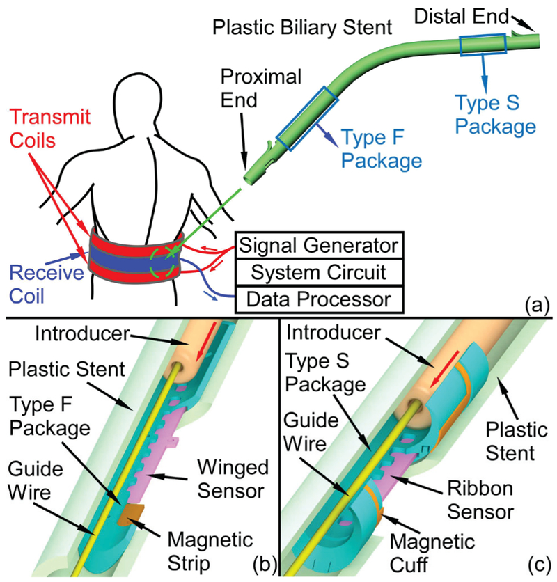
A monitoring system that can provide a direct and wireless measurement of biomass accumulation in a plastic biliary stent with an integrated magnetoelastic sensor is shown in Fig. 1 (a). The system consists of the implanted sensor and biasing magnet(s), as well as the external readout unit. The external readout unit first generates a burst sinusoidal current through the transmit coils, resulting in a magnetic signal for exciting the implanted sensor. The magnetic response of the sensor is then detected by the receive coil and recovered through analog and digital signal processing in the external readout unit. The frequency of the interrogating signal is swept, step-by-step, to measure the frequency response of the sensor. The transmit and receive coils are placed around the midsection of the patient in a manner similar to that of a belt.
Fig. 1.
(a) Conceptual diagram of the magnetoelastic monitoring system and the plastic biliary stent. (b) Cross-sectional views of Type F and (c) Type S 3D printed packages, which integrate magnetoelastic sensors and magnets. The Type F package can be assembled near the proximal end of a plastic stent while the Type S package can be assembled near the distal end. Both package designs do not impede the stent as it is loaded on the guide wire and introducer.
An open challenge for incorporating the sensor into stents is the encapsulation of the sensors. Without appropriate encapsulation, the sensors are damaged by delivery tools during implantation. This paper evaluates two encapsulation approaches that can overcome challenges specific to the endoscopic deployment of the instrumented plastic biliary stents (Fig. 1 (b) and (c)). Each approach uses a 3D printed package to encapsulate a sensor to: 1) protect the sensor from being damaged by the introducer – a standard component of the endoscopic delivery, 2) provide mechanical stability to the sensor to endure the bending experienced during endoscopic delivery, 3) provide features that allow interaction between the sensor and the fluids and biomass within the stent, and 4) accommodate permanent magnets to provide a stable DC bias and thus establish a more integrated sensor module.
Two types of packages are described, each for positioning at different locations within a stent that have different mechanical requirements. The Type F package (Fig. 1 (b)), representing a mechanically flexible packaging approach, encapsulates a winged sensor and two magnetic strips, and can be assembled near the proximal end of a plastic biliary stent (Fig. 1 (a)), which is the end located near the liver. The Type S package (Fig. 1 (c)), representing a mechanically stiff packaging approach, encapsulates a simple ribbon sensor and provides a mounting surface on which is placed a magnetic cuff for sensor biasing. This package type can be assembled near the distal end of the stent (Fig. 1 (a)), which is the end located near the duodenum. Figs. 1 (b) and 1 (c) show the cross-sectional views of both types of packages with the guidewire and introducer passing through the stents. Both designs are shown to protect embedded sensors during the implantation process.
Section II presents the design of the two types of packages and the design of magnetoelastic sensors and magnets for the packages. Section III describes the full packaging and assembly processes for the two types of packages. Section IV shows experimental methods and benchtop and in situ results obtained with a porcine carcass. Section V concludes the paper.
II. DESIGN
A. Package Design
For the proposed application, the package material should be biocompatible, chemically inert at body temperature, and electromagnetically transparent. The fabrication technique should facilitate the integration of features with high resolution (a few hundred micrometers) and, if possible, be inexpensive. Of critical importance, the package - once assembled to the stent - must be capable of passing through the endoscope during delivery without impeding the capability of the endoscopist to place the stent as desired. The stents used in this work are G22056 and G21847 Cotton-Leung biliary stents (Cook Medical, Bloomington, IN, USA) which have the outer diameters of 0.33 cm (10 Fr) and 0.38 cm (11.5 Fr), and lengths of 7 cm and 9 cm, respectively. The standard endoscopic procedure requires the aid of a side-view endoscope, which has a camera to locate the position of the biliary orifice and an elevator to adjust the direction of the stent (Fig. 2). With the elevator lowered, the stent (and packaged sensor) must navigate a radius of curvature of approximately 7.2 cm; with the elevator raised, this curvature is approximately 2 cm. Once the proximal end of the stent is engaged in the biliary orifice, the elevator can be lowered for a smoother delivery and the stent can be then pushed fully into the bile duct by the introducer assembly. Therefore, the proximal portion of the stent must remain flexible, whereas the flexibility of the distal portion of the stent is not essential. Consequently, a flexible (Type F) package can be used in the proximal portion of the stent whereas a stiff (Type S) package can be used in the distal portion.
Fig. 2.
The elevator of the endoscope is (a) lowered and (b) raised at maximum angle. The largest radius of curvature is approximately 7.2 cm (elevator lowered) while the smallest is 2 cm (elevator raised), (c) Schematic of the endoscope profile and the estimated minimum radius of curvature of the stent.
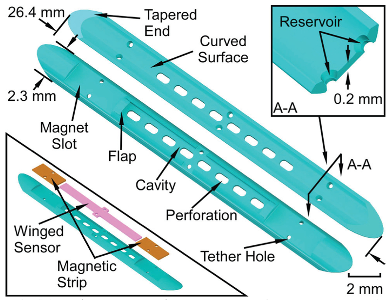
As noted previously, the Type F and Type S packages differ mainly in their bending flexibility, with the Type F package (Fig. 3) intended to be flexible and the Type S package (Fig. 4) intended to be rigid. Features common to both types include a perforated cavity in which the sensor is placed to allow contact with the biliary fluid, tapered ends and curved surfaces to guide the introducer over the package smoothly, and tether holes that facilitate stitching of the package to the components and the stent. The stitching is performed with polyethylene (PE) thread that is subsequently melted by heating in order to reduce its profile and fix it in place.
Fig. 3.
Schematic of the top and bottom views of the Type F package. The bottom left inset shows the assembly of the magnetic strips and winged sensor. The top right inset indicates a cross section view of the reservoir feature.
Fig. 4.
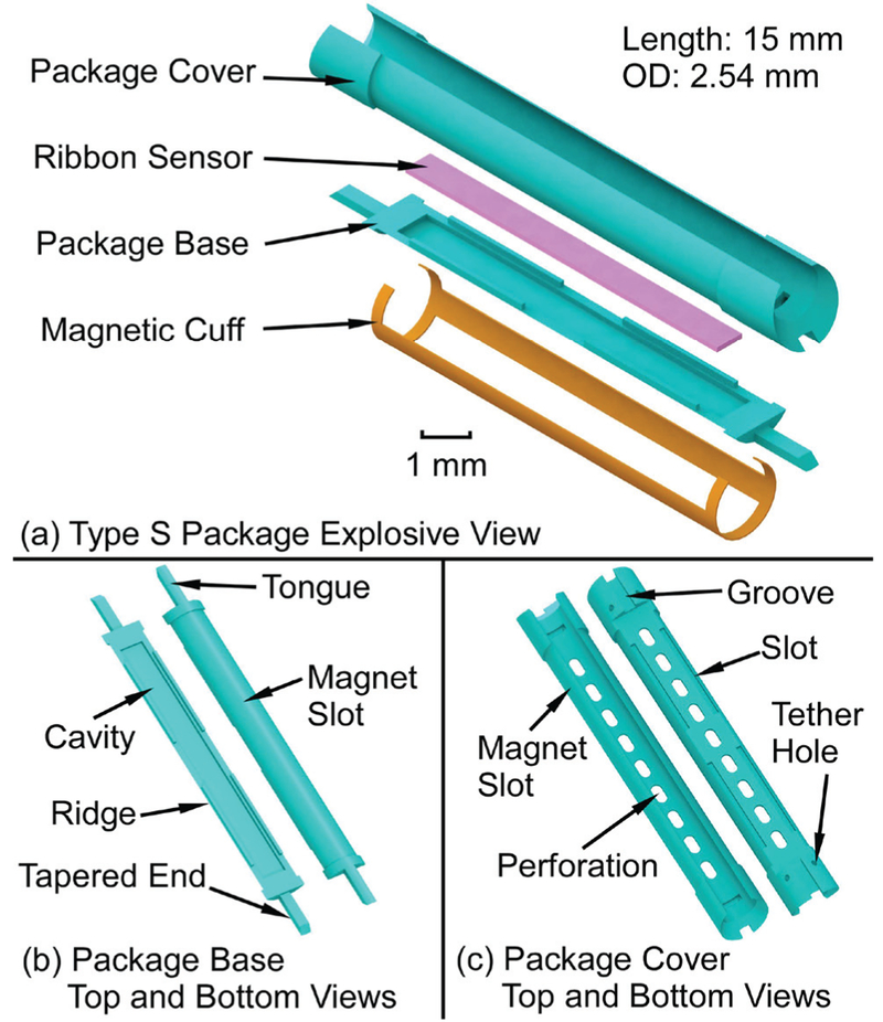
(a) The exploded view of the Type S package, (b) The top and bottom views of the package base, (c) The top and bottom views of the package cover.
The Type F package (Fig. 3) is 26.4 mm long, 2.3 mm wide and only 0.53 mm thick. The sensor cavity within the package is 13 mm long, 1.2 mm wide, and 0.25 mm deep. The flap located at each end of the sensor cavity is to prevent the sensor from sliding out of the cavity. The flaps are 0.45 mm long, 1 mm wide, and only 0.13 mm thick. The two magnet slots are each 4 mm long and 1.7 mm wide. There are six tether holes, each with a feature called the reservoir; the reservoir accommodates reflowed PE formed when the PE tethers are heated. This reflowed PE anchors the tether to the package and also reduces the topographical variation on the upper surface of the package, which reduces the friction when the introducer slides over the package.
In the Type S package (Fig. 4), the ribbon sensor is encapsulated by the package base and cover and a magnetic cuff is clamped on the package. This structure allows the stiffness of the package to be tailored, mitigating any curvature that may be imposed by the bile duct, and keeping the instrumented portion of the stent straight so that the sensor may easily vibrate in the preferred longitudinal mode shape. The overall length is 15 mm and the outer diameter is 2.54 mm. The package base has a cavity that is 13 mm long, 1.2 mm wide, and 0.18 mm deep. This cavity houses a ribbon sensor (12.5 mm × 1 mm × 60 (μm) that is otherwise unconstrained. This stands in contrast to the Type F package, which utilizes a single-piece package with the sensor centrally anchored to the package by a PE tether. Four ridge features (4.5 mm × 0.15 mm × 0.2 mm) and two tongue features (1.77 mm × 0.52 mm × 0.31 mm) in the package base are designed to match and interlock with the package cover, which has complementary slots and grooves. The hollowed area in the package cover is designed to be large enough to let the introducer (01.7 mm) pass through. Both the package base and cover are reduced in diameter by 100 μm in selected areas to form magnet slots.
The package should not substantially increase the flow resistance of the stent. According to the Darcy-Weisbach equation [16], the pressure loss ΔP in a cylindrical tube of uniform diameter D is proportional to length L:
| (1) |
where μ is the dynamic viscosity of the fluid, and O is the volumetric flow rate. The flow resistance R can be represented as
| (2) |
For a 90 mm long 11.5 Fr stent, the flow resistance change for the entire stent with the Type F package is approximately +13% assuming the equivalent diameter of the channel which contains the package is 2.4 mm, while that of the stent is 2.63 mm. Similarly, the total flow resistance change for a 70 mm long 10 Fr stent with the Type S package is approximately +83% when the diameter of the hollowed area is 1.8 mm and the diameter of the stent is 2.53 mm.
The two packaging approaches here have significantly different effects on the bending stiffness of the stent. The bending stiffness of a portion of an 11.5 Fr stent (3.83 mm OD and 2.63 mm ID) containing the Type F package can be calculated as the sum of the bending stiffness of each component:
| (3) |
where E is the Young’s modulus of the object, I is the second moment of area, and L is the length [17], For a cylindrical tube, , while for a rectangular beam offset from the bending axis of the stent by a distance – which is a suitable representation of the Type F package for this calculation– . The parameters ro and ri are the outer and inner radii of the tube while b and h are the width and thickness of the beam (2 mm and 530 (μm, respectively). The Young’s moduli of the stent and the package materials are 700 MPa and 1463 MPa, respectively. For the Type F package (L = 26.4 mm), kFtotal is estimated to be 19.5 N/mm.
Similarly, the total bending stiffness of a 10 Fr stent (3.33 mm OD and 2.53 mm ID) containing a 20 mm long Type S package (approximated as a cylinder with 2.53 mm OD and 1.8 mm ID) is estimated to be kstotal = 29.8 N/mm. The change in the bending stiffness of the stent due to the Type F package is 31 % while the change due to the Type S package is 78%. The calculated bending stiffness of the Type S package does not include the additional magnetic cuff, which, due to the large Young’s modulus of the Arnokrome™ 5 material and the geometry of the cuff, adds further stiffness to the Type S package overall.
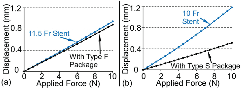
The changes to the stent bending stiffness due to the Type F and Type S packages are also simulated with finite element analysis (FEA) using COMSOT Multiphysics™ to verify the simplified analytical calculation described above. The material properties of the stent (polyethylene, E = 0.7 GPa, p = 0.95 g/cm3, v = 0.42) and the package (M3 crystal resin, E = 1.46 GPa, p = 1.02 g/cm3, v = 0.42) are the same as those used in the analytical calculation. Figure 5 (a) presents the cross sectional view of the 11.5 Fr stent with the Type F package, and the boundary conditions used in the FEA model. The model of the stent is 26.4 mm long and the package is affixed to the inner side wall of the stent model. Some features of the package like the flaps are removed because these features do not significantly affect the result but do substantially increase the simulation time. The loads and conditions are defined to approximate the classical “three-point bending test”. Points a and b have zero displacement along the y axis to prevent rolling, point c is fixed in all directions, and point d has zero displacements in y and z directions but can move along the x axis. An external force which increases from 0 to 10 N is applied on the middle of the stent model in the negative z direction. The length of the stent model loaded by the force is 2 mm. Fig. 5 (b) shows the deformation of the Type F package when the applied force is 10 N. (The deformed stent is hidden in this view.) The maximum displacement of the stent model, which is at the middle of the stent model, is less than 0.90 mm. The bending stiffness of this stent portion with and without the Type F package are illustrated by the slopes of the load vs. displacement lines (Fig. 6 (a)). The bending stiffness of this portion of the stent only increases from 10.61 N/mm to 11.34 N/mm (+7%).
Fig. 5.
(a) Cross sectional view of the 11.5 Fr stent with the Type F Package. The stent length is 26.4 mm. The external force is applied on the red surface of the stent, which is 2 mm in length, (b) FE A simulation result of deformation of the Type F package when under 10 N applied force.
Fig. 6.
Simulated displacement of the stent with and without the (a) Type F and (b) Type S packages due to the external applied force.
Similarly, a portion of a 10 Fr stent with and without the Type S package is also simulated in COMSOL. In this simulation, the bending stiffness of the stent portion increases from 8.41 N/mm to 19.48 N/mm (+132%), as shown in Fig. 6 (b)). The added stiffness in this region provides a consistent mechanical environment for the resonator even when the stent is bent, as demonstrated experimentally in section IV.B. Although the absolute values of the simulated bending stiffness are not the same as the analytical calculation (an effect mainly of the radial compression of the stent portion in the simulation), the relative changes in the bending stiffness due to each package are similar in both analytical and FEA estimates.
B. Magnetoelastic Sensor Design
A two-layer bonded magnetoelastic ribbon-shaped sensor provides the necessary compactness for this application. The resonant frequency f of the vibration along the longitudinal axis of the unloaded sensor is determined by:
| (4) |
where Ls is the length of the ribbon, Es is the Young’s modulus, ps is the density of the sensor. The fundamental resonant frequency provides the highest signal strength. For a 12.5 mm long and 1 mm wide ribbon sensor fabricated from Metglas™ 2826MB (£, = 100 GPa, ps = 7.90 g/cm3), the expected resonant frequency is 168.7 kHz, which is confirmed by the finite element analysis (FEA) result (COMSOL Multiphysics) [11], For the sensor used in the Type F package, two additional 0.8 mm × 0.4 mm wing features with two Ф0.3 mm tether holes are located in the middle of the sensor for anchoring it in the package. The maximum displacement of the winged sensor is 30 nm at 169 kHz according to the FEA simulations (with a simulated 22.3 A/m interrogation field, Fig. 7), while that of the ribbon sensor shows a similar result of 32 nm at 166 kHz.
Fig. 7.
FEA simulation result of the winged sensor – used with the Type F packages – with the wings anchored. The sensor resonates at 169 kHz in a longitudinal mode shape with a maximum displacement of 30 nm.
C. Bias Magnet Design
The operating point of the sensor is set by the bias (steady) magnetic field. Due to the coupling between the magnetism and strain, the bias magnetic field also affects the apparent Young’s modulus of the material, the phenomenon which is called the ΔE effect [18], The incorporation of a magnet (or magnets) into the package assembly alongside the sensor provides a fixed magnetic field, eliminating the need to align the orientation of external interrogation equipment. To maintain the overall flexibility of the Type F package, the magnets must be close to the inner sidewall of the stent and as short as possible. Therefore, two Arnokrome™ 5 magnetic strips (4 mm × 1.5 mm × 0.6 mm each) are located close to the two ends of the winged sensor (Fig. 3). An appropriate distance between the magnets and the sensor is empirically determined to be 100 μm. Two (DO.3 mm tether holes in the middle of each magnet accommodate features within the package, fixing the position of each magnet. For the Type S package, the DC magnetic bias is provided by two Arnokrome™ 5 magnetic strips (14 mm × 1 mm × 0.6 mm each), which are oriented along the length of the package and held in place on the package by two cuffs that are monolithically formed at the ends of the strips, as shown in Fig. 4 (a). In this case, the magnetic strips can also increase the bending stiffness of the assembly.
III. FABRICATION AND ASSEMBLY
A. Fabrication of Packages
The need for flexibility, electromagnetic transparency, and cost exclude metals as the packaging materials and point toward the use of polymers. The “M3 crystal” resin (acrylated urethane, UV curable plastic, 3D Systems Inc., U.S.) is a USP (United States Pharmacopeia) Class VI biocompatible rated plastic 3D printing material [19, 20], Other common 3D-printing materials like polylactic acid (PLA) and acrylonitrile butadiene styrene (ABS) fail to meet the biocompatibility requirement [21], The multiJet (MJP) printing technology (3D Systems Inc., U.S.) can print and cure the structure formed by “M3 crystal” resin layer by layer with a layer resolution of 16 μm and a minimum (lateral) feature resolution of 200 μm [22, 23],
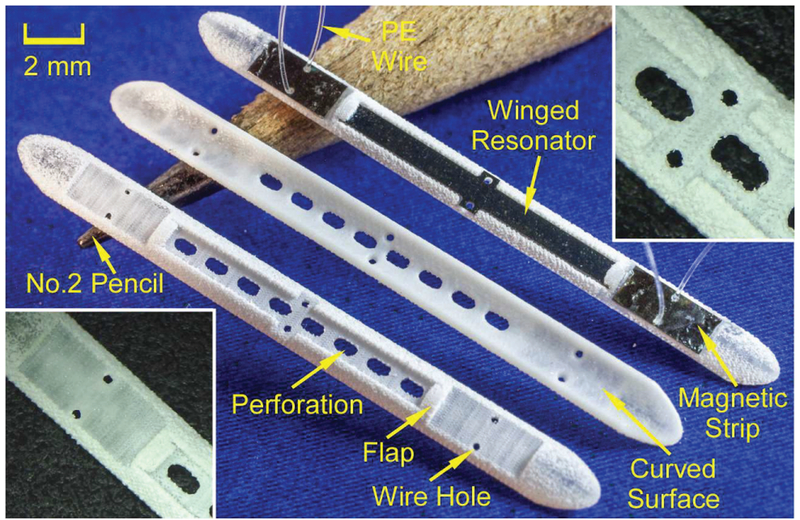
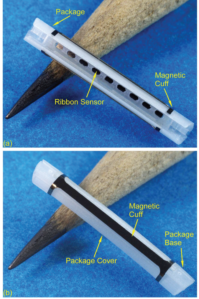
The Type F and S packages were printed by the ProJet 3500HD Max (3D Systems Inc.), as shown in Fig. 8 and Fig. 9, respectively. A Type F package with integrated winged sensor and magnetic strips is also shown in Fig. 8. The top and back views of the package bases and covers of the Type S package are shown in Fig. 9 (a) and (b), respectively. The front and side views of a Type S package with integrated ribbon sensor and rolled magnetic cuff are shown in Fig. 10 (a) and (b), respectively.
Fig. 8.
Top and back views of the 3D printed Type F package. A resonator and magnets integrated with the package is also shown. The insets show details near the flap (bottom left) and the center perforations (top right).
Fig. 9.
(a) Top and back views of the 3D printed Type S package base, (b) Top and back views of the 3D printed Type S package cover.
Fig. 10.
(a) Front and (b) side views of the Type S package with the magnetic cuff.
B. Fabrication of Sensors and Magnets
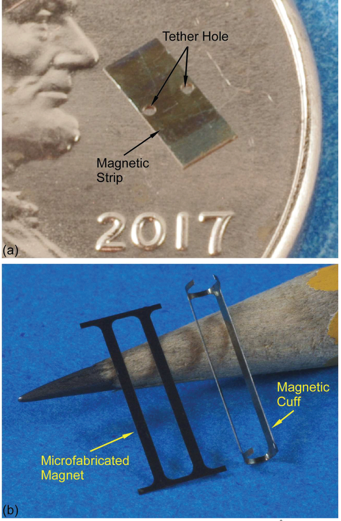
The magnetoelastic sensor material was the iron-rich amorphous ferromagnetic alloy Metglas™ 2826MB foil (28 μm thick). Two layers of the foil were bonded together by using the gold-indium (Au-In) eutectic bonding process [24–26] in order to enable resonators with larger signal without affecting the footprint of the resonators. The bonded Metglas™ foils were then machined to form winged sensors and ribbon sensors by using micro electro-discharge machining (μEDM) [27, 28] and finally coated by 100 nm thick AI2O3 using the atomic layer deposition (ALD) [29] technique to prevent corrosion and for purposes of biocompatibility, as shown in Fig. 11. The μEDM and ALD approaches were also used to machine and coat the Arnokrome™ 5 magnetic alloy foils, [30], as shown in Fig. 12.
Fig. 11.
Au-In bonded (a) winged sensor and (b) ribbon sensor coated with 1000 Å Al2O3.
Fig. 12.
(a) Microfabricated magnetic strip coated with 1000 Å Al2O3 for the Type F package, (b) Microfabricated magnetic strip (left) and the magnetic cuff (right) after rolling for the Type S package.
C. Assembly
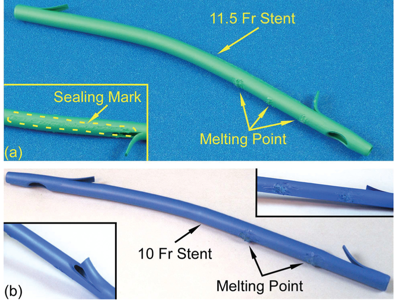
The assembly procedure for the Type F package was as follows. First, the winged sensor and the two magnets were placed in the proper position of the package (as shown in Fig. 3). Then, six 150 |im diameter PE tethers were threaded through the holes on the package and those on the magnetic strips and winged sensor. The top end of each PE tether was tied to form a square knot and then locally heated to reflow into the reservoir. Next, bilateral 20 mm long slices were cut from the proximal flap hole by a razor blade, and the resulting flap was peeled open to facilitate access to the internal stent lumen. Subsequently, the PE tethers on the package were threaded through the holes on the stent, which were aligned to the positions of the holes on the package, and were pulled taut to bring the package close to the inner sidewall of the stent. These tethers were then used to tie three square knots on the outside of the stent. The slices in the stent were closed and sealed by a heated soldering iron. The soldering iron was also used to melt the knots on the outside of the stent into the material of the stent and to smooth the resulting bumps. The assembled 11.5 Fr stent is shown in Fig. 13 (a).
Fig. 13.
(a) Side view of an assembled 11.5 Fr stent with Type F package integrated. The melting points and the sealing mark can be observed, (b) Side view of an assembled 10 Fr stent with Type S package integrated. The melting points can be observed in the top-right inset. The stent does not need to be cut for assembly.
The Type S package required only four PE tethers, all of which were to the distal end of the stent. The Type S package was assembled to the stent without slicing the stent. A 10 Fr stent (02.53 mm) was used, while other processes were similar to that for the Type F package, as shown in Fig. 13 (b).
IV. Experimental methods and results
A. Mechanical Evaluation
The purpose of the mechanical evaluation was to examine the robustness of the package during implantation. The first test was to verify the ability for an introducer to pass through the stent with the package assembled inside, without damaging the packaged sensor. A 2 mm diameter introducer (Cook Endoscopy, G25381) was inserted into and removed from a biliary stent with the assembled Type F package, respectively, 20 times. The overall insertion and removal processes were smooth as determined manually. The stent was sliced open after each trial for observation and sealed for the next trial. Similarly, a 1.7 mm diameter introducer (Cook Endoscopy, G25377) was used to evaluate a biliary stent with the Type S package. Neither the packages nor the PE tethers broke during these tests, and no snagging or wear was observed for any component.
The second mechanical test evaluated the elasticity and bending stiffness of the two types of package during the delivery through the endoscope. The stent was inserted in the soft tube and the tube was bent to progressively reduce the radius of curvature of 10 cm to 5 cm with 1 cm intervals. The stent and package were bent in three directions during separate trials of this test: concave and convex along the longitudinal axis of the package, and along the lateral axis of the package. For the Type F package, when bending the stent along the width axis of the package, the stent would partially rotate within the soft tube in order to align the more flexibl e bending axis of the package with the applied bending direction and thus reduce the applied stress. For the Type S package, the region of the stent where the package was located remained straight even as the rest of the stent was curved in the soft tube. In each test case, the tube was maintained in a bent condition for 1 minute and then removed from the soft tube for examination. The packages did not have cracks and the PE tethers did not break in all test cases.
B. Signal Evaluation
In this work, the external readout unit included two 30-turn parallel connected transmit coils and a 28-turn receive coil to generate AC magnetic field and receive the response signal from the resonator, respectively. The AC magnetic field was excited by a sine wave generator (PXI 5412, NI) controlled by a switch. In this approach, a sine wave burst at one frequency is transmitted to excite the sensor, then the sensor “ring down” response is measured between bursts. After low noise preamplification (Stanford Research Systems SR 570), the sensor response signal was recovered by a series of digital signal processing (DSP) techniques after acquisition with a PXI 1082 module. The DSP, implemented in Lab VIEW, used averaging, moving bandpass filtering, quadrature mixing, and low pass filtering to minimize the noise. The total energy of the recovered “ring down” signal at each frequency was calculated via integration and compared to the total energy of the noise to get a signal-to-noise ratio (SNR) plot along the swept frequency range.
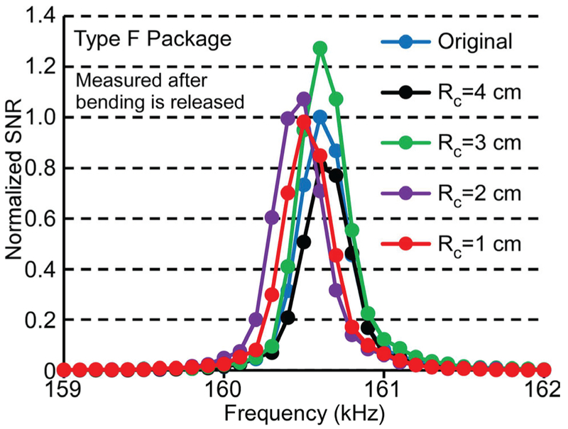
The sensor signal was measured after each bending test case mentioned above, after allowing the stent to revert to its undeformed shape. The test results demonstrated that none of the bending cases affected the signal or resonant frequency. Typical frequency responses of the Type F package are shown in Fig. 14; these measurements were taken following convex bending of the stent to radii of curvature varying from 4 cm to 1 cm, and its subsequent return to the undeformed state.
Fig. 14.
Frequency response of a typical sensor in the Type F package after the convex bending test with radius of curvature from 4 cm to 1 cm. Measurements taken after releasing the stent from the bent condition.
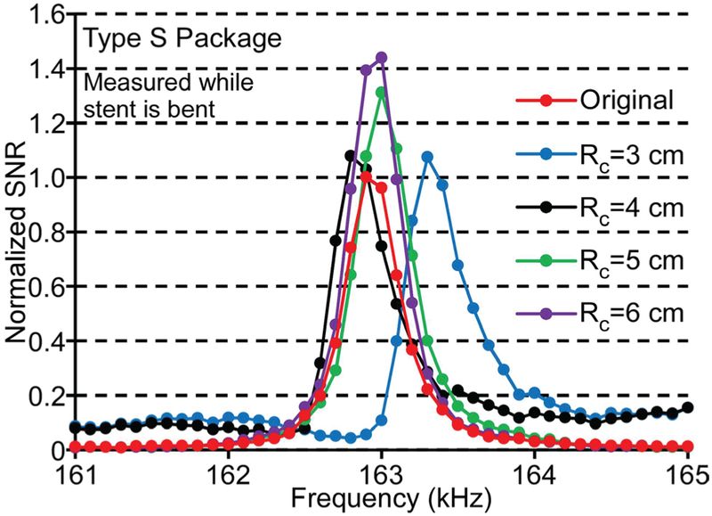
Although the tests described above showed that the sensor in the Type F package survived when the stent was relieved from the bending state, the average signal of the sensor measured while the stent was still bent decreased dramatically when the radius of curvature was smaller than 10 cm, as listed in Table I. The comparable bending test results from the Type S package are also shown in Table I, while typical frequency responses of a resonator encapsulated in a Type S package under the convex bending condition with global radii of curvature from 6 cm to 3 cm are shown in Fig. 15. The signal amplitude remained high and the resonant frequency changed little (<0.2%) for the Type S package even as the global radius of curvature of the tube was reduced to 3 cm. The observed variations of the signal amplitude and resonant frequency were likely due to changes in resonator internal stress and boundary conditions as the stiff package curves slightly and the boundaries of the resonator came into contact with the package. The variations in the resonant frequency in these bending tests were much smaller than those expected due to sludge accumulation (≈ 10%). This showed that the Type S package could maintain a consistent mechanical environment for the ribbon sensor while the remainder of the stent accommodated the bending of the tube.
TABLE I.
EXPERIMENTALLY MEASURED RADIUS OF CURVATURE (Rc), AVERAGE NORMALIZED SIGNAL (Sn) AND AVERAGE RESONANT FREQUENCY (f0) FOR THE Type F and Type S package, under progressive levels of applied CURVATURE. MEASUREMENTS TAKEN WHILE STENT WAS MAINTAINED IN A BENT CONDITION.
| Rc (cm) | Sn | f0 (kHz) |
|---|---|---|
| Type F Package | ||
| Straight | 1.00 | 160.5 |
| 10 | 0.57 | 160.6 |
| 9 | 0.09 | 160.6 |
| 8 | 0.06 | 160.5 |
| 7 | 0.07 | 160.6 |
| 6 | 0.04 | 160.5 |
| Type S Package | ||
| Straight | 1.00 | 163.1 |
| 6 | 0.91 | 163.3 |
| 5 | 0.96 | 162.8 |
| 4 | 0.83 | 163.0 |
| 3 | 0.90 | 163.0 |
Fig. 15.
Frequency response of a typical sensor in the Type S package under the convex bending condition with radius of curvature from 6 cm to 3 cm. Measurements taken while the stent was maintained in the bent condition.
C. In situ Evaluation
The Type F package was also tested in an in situ experiment in the bile duct of a 22 kg female domestic swine carcass. The approval for the animal use protocol was obtained from the University of Michigan IACUC (protocol #6901). The long diameter of the carcass was 23 cm and its short diameter was 17.6 cm when the carcass was laid supine. Fig. 16 (a) shows the schematic of the experimental setup - the transmit coils (red) and receive coil (blue) wrapped around a swine. Fig. 16 (b) is a photograph of the coils in position around a carcass. A laparotomy was performed on the carcass, and a typical instrumented stent was inserted in the bile duct after exposing its distal orifice with an incision near the small intestine. Fresh bile solution was injected into the bile duct and the internal organs were replaced in the carcass. The signal from a typical instrumented stent measured in situ in the bile duct of a swine carcass (with the inner lumen of the stent full of a mixture of bile and other biological fluids) demonstrated a quality factor of 397, SNR of 76, and resonant frequency of 159 kHz. In comparison, the benchtop experimental result of a typical sensor encapsulated by the Type F package has a quality factor of 615, SNR of 103, and resonant frequency of 162 kHz in air, as shown in Fig. 16 (c). The shifts in the frequency response were due to the immersion of the encapsulated sensor in bile and other biological fluids, which indicates that the package allows the resonator to remain sensitive to the surrounding environment. The measured wireless range was ≈10 cm in both cases.
Fig. 16.
(a) Schematic of the transmit coils and receive coil wrapping around the swine as a “belt”, (b) The coil belt around a swine carcass, (c) Frequency responses of a magnetoelastic sensor in a Type F package measured during a benchtop experiment (in air) and measured in situ in the bile duct of a swine carcass (immersed in a mixture of bile and other biological fluids).
V. Conclusion
Two types of 3D-printed polymeric packages for magnetoelastic sensors and bias magnets were fabricated, assembled in plastic biliary stents, and evaluated for performance. The Type F package showed the advantage of flexibility during the delivery process while the Type S package maintained sensor signal even when the stent was under a bending condition. The packaging and assembling processes did not affect the signal or the resonant frequency of the sensors. The benchtop experimental work described here also demonstrated that the packages could protect the sensor from being damaged by the introducer and during the tortuous endoscopic delivery of the stent. The in situ evaluation with the Type F package encapsulated sensor further demonstrated that the packaging allowed the sensor to interact with and detect changes in the fluidic environment in the bile duct.
The test results indicate that 3D printed packages offer a promising avenue for protecting magnetoelastic sensors during implantation. The characteristics of biocompatibility and high-resolution features allow the 3D printed packages to be applied in the small ducts and vessels of the human body. For the Type F package, the bending test results imply the reduction of signal if the packaged sensor experiences some curvature. While the rigidity of the Type S package can overcome the issue with in situ curvature of the bile duct, it may make delivery of the stent more challenging. Another potential issue with the Type S package is that the overall flow area of the stent at the position of the package is significantly reduced, which may reduce the longevity of the patency of the stent. Therefore, improvements overcoming these challenges are part of continuing work.
ACKNOWLEDGMENT
The authors gratefully acknowledge Dr. Richard Kwon, Gail Rising, and Amber Yanovich for assistance with the in situ evaluation. Advice from Dr. Grace Elta is also gratefully acknowledged. This work was supported in part by the National Institutes of Health (R01DK102663) and the University of Michigan. The content is solely the responsibility of the authors and does not represent the official views of the National Institutes of Health.
References
- [1].Pfau P et al. , “Pancreatic and biliary stents.” Gastrointestinal Endoscopy, Vol. 77, No. 3, pp. 319–327, 2013. [DOI] [PubMed] [Google Scholar]
- [2].Libby E, and Leung J, “Prevention of biliary stent clogging: a clinical review,” Am. J. Gastroenterology, Vol. 91, No. 7, pp. 1301–7, 1996. [PubMed] [Google Scholar]
- [3].Donelli G et al. , “Plastic biliary stent occlusion: factors involved and possible preventive approaches,” Clinical Med. Res, Vol. 5, No. 1, pp. 53–60, 2007. [DOI] [PMC free article] [PubMed] [Google Scholar]
- [4].Colombato L, “The role of transjugular intrahepatic portosystemic shunt (TIPS) in the management of portal hypertension,” J. Clin. Gastroenterol, Vol. 41, Suppl. 3, pp. S344–51, 2007. [DOI] [PubMed] [Google Scholar]
- [5].Dangas G, and Kuepper F, “Restenosis: repeat narrowing of a coronary artery: prevention and treatment,” Circulation, Vol. 105, pp. 2586–2587, 2002. [DOI] [PubMed] [Google Scholar]
- [6].Rosevear H et al. , “Retrograde ureteral stents for extrinsic ureteral obstruction: nine years’ experience at University of Michigan,” J. Urology, Vol. 70, No. 5, pp. 846–50, 2007. [DOI] [PubMed] [Google Scholar]
- [7].Serruys P et al. , “Coronary-artery stents,” New England J. Med, Vol. 354, pp 483–95, 2006. [DOI] [PubMed] [Google Scholar]
- [8].Tse F, et al. , “Nonoperative imaging techniques in suspected biliary tract obstruction,” HPB (Oxford), Vol. 8, No. 6, pp. 409–425, 2006. [DOI] [PMC free article] [PubMed] [Google Scholar]
- [9].Judah J and Draganov P, “Endoscopic therapy of benign biliary strictures,” World J Gastroenterol, Vol. 13, No. 26, pp. 3531–3539, July 2007. [DOI] [PMC free article] [PubMed] [Google Scholar]
- [10].Green S et al. , “In vivo and in situ evaluation of a wireless magnetoelastic sensor array for plastic biliary stent monitoring,” Biomedical Microdevices, Vol. 15, No. 3, pp. 509–517, June 2013. [DOI] [PMC free article] [PubMed] [Google Scholar]
- [11].Green S and Gianchandani Y, “Wireless magnetoelastic monitoring of biliary stents,” Journal of Microelectromechanical Systems, Vol. 18, No. 1, pp. 64–78, February 2009. [Google Scholar]
- [12].Green S and Gianchandani Y, “Tailored magnetoelastic sensor geometry for advanced functionality in wireless biliary stent monitoring systems,” Journal of Micromechanics and Microengineering, Vol. 20, No. 7, 075040, 13 pp., 2010. [Google Scholar]
- [13].Engdahl G, Handbook of Giant Magnetostrictive Materials, Ac ademic Press, pp. 1–19, 2000. [Google Scholar]
- [14].Grimes C et al. , “Theory, instrumentation and applications of magnetoelastic resonance sensors: a review,” Sensors, Vol. 11, pp. 2809–2844, 2011. [DOI] [PMC free article] [PubMed] [Google Scholar]
- [15].Grimes C, et al. , “Wireless magnetoelastic resonance sensors: a critical review,” Sensors, Vol. 2, pp. 294–313, 2002. [Google Scholar]
- [16].Kirby B, Micro- and Nanoscale Fluid Mechanics: Transport in Microfluidic Devices. Cambridge University Press, 2010. [Google Scholar]
- [17].Beer F et al. , Mechanics of Materials, 7th Edition. McGraw-Hill Education, 2014. [Google Scholar]
- [18].Pepakayala V et al. , “Passive Wireless Strain Sensors Using Microfabricated Magnetoelastic Beam Elements”, JMEMS, 2014. [Google Scholar]
- [19].VisiJet M3 Crystal resin material datasheet. [Online], Available: http://www.cbmwales.co.ukAvp-content/uploads/2015/05/projet-3500-plastic-0214-us-web.pdf, accessed Apr. 2018.
- [20].ProJet 3500 Series Professional 3D Printers User Guide. [Online], Available: http://www.aniwaa.com/product/3d-printers/3d-systems-projet-3500-hd-max/, accessed Apr. 2018.
- [21].Waheed S et al. , “3D printed microfluidic devices: enablers and barriers,” Lab on a Chip, Vol. 16, pp. 1993 –2013, 2016. [DOI] [PubMed] [Google Scholar]
- [22].Sochol R et al. , “3D printed microfluidic circuitry via multijet-based additive manufacturing,” Lab on a Chip, Vol. 16, pp. 668–678, 2016. [DOI] [PMC free article] [PubMed] [Google Scholar]
- [23].Bhattacharjee N et al. , “The upcoming 3D-printing revolution in microfluidics,” Lab on a Chip, Vol. 16, pp. 1720–1742, 2016. [DOI] [PMC free article] [PubMed] [Google Scholar]
- [24].Viswanath A, et al. , “Metglas-Elgiloy bi-layer, stent cell resonators for wireless monitoring of viscosity and mass loading,” Journal of Micromechanics and Microengineering, Vol. 23(2), No. 025010, February 2013. [Google Scholar]
- [25].Aktakka E et al. , “Wafer-level integration of high-quality bulk piezoelectric ceramics on silicon,” IEEE Transactions on Electron Devices, Vol. 60, No. 6, pp. 2022–2030, June 2013. [Google Scholar]
- [26].Tang J et al. , “Miniature wireless magnetoelastic resonant motor with frequency selectable bidirectional rotation,” Journal of Microelectromechanical Systems, Vol. 22, No. 3, pp. 730–738, June 2013. [Google Scholar]
- [27].Takahata K and Gianchandani Y, “Batch mode micro-electro-discharge machining,” Journal of Microelectromechanical Systems, Vol. 11, No. 2, pp. 102–110, April 2002. [Google Scholar]
- [28].Richardson M and Gianchandani Y, “Wireless monitoring of workpiece material transitions and debris accumulation in micro-electro-discharge machining,” Journal of Microelectromechanical Systems, Vol. 19, No. 1, pp. 48–54, February 2010. [Google Scholar]
- [29].An S, et al. , Vacuum sealing using atomic layer deposition of AI2O3 at 250°C,” Journal of Vacuum Science and Technology A: Vacuum, Surfaces and Films, Vol. 32, No. 1, January 2014. [Google Scholar]
- [30].Arnokrome 5 Specification datasheet. [Online], Available: https://www.comsoi.eom/forum/thread/attachment/321842/ARNOKROME-5-Specification-Feb-2011-79042.pdf, accessed Apr, 2018.


