Abstract
While sensory information is encoded by firing patterns of individual sensory neurons, it is also represented by spatiotemporal patterns of activity in populations of the neurons. Postsynaptic interneurons decode the population response and extract specific sensory information. This extraction of information represented by presynaptic activities is a process critical to defining the input–output function of postsynaptic neuron. To understand the “algorithm” for the extraction, we examined directional sensitivities of presynaptic and postsynaptic Ca2+ responses in dendrites of two types of wind-sensitive interneurons (INs) with different dendritic geometries in the cricket cercal sensory system. In IN 10-3, whose dendrites arborize with various electrotonic distances to the spike-initiating zone (SIZ), the directional sensitivity of dendritic Ca2+ responses corresponded to those indicated by Ca2+ signals in presynaptic afferents arborizing on that dendrite. The directional tuning properties of individual dendrites varied from each other, and the directional sensitivity of the nearest dendrite to the SIZ dominates the tuning properties of the spiking response. In IN 10-2 with dendrites isometric to the SIZ, directional tuning properties of different dendrites were similar to each other, and each response property could be explained by the directional profile of the spatial overlap between that dendrite and Ca2+-elevated presynaptic terminals. For IN 10-2, the directional sensitivities extracted by the different dendritic-branches would contribute equally to the overall tuning. It is possible that the differences in the distribution of synaptic weights because of the dendritic geometry are related to the algorithm for extraction of sensory information in the postsynaptic interneurons.
Keywords: decoding, Ca2+-sensitive dye, optical recording, dendrites, insect, directional sensitivity
Introduction
Spatial distribution of synapses and the geometry of the dendritic tree are crucial factors for information processing by a sensory interneuron, because these factors and electrical properties of dendrites have important influences on the integration of synaptic inputs that define input–output functions of the neuron (for review, see Borst and Egelhaaf, 1994). In vivo Ca2+ imaging of the dendrites of visual interneurons, such as fly tangential cells (Single and Borst, 1998) and starburst amacrine cells in mammalian retina (Euler et al., 2002), demonstrated the dendritic integration processes of visual information. However, there are no studies addressing how individual dendrites of the sensory interneuron extract the sensory information represented by a population of the receptor neurons. To understand the “decoding algorithm” for the extraction of sensory information by dendrites, it is beneficial to examine the stimulus-response properties of presynaptic terminals of sensory afferents and postsynaptic sites on dendrites of the functionally identified interneuron. In this study, we adopted a dual-view Ca2+ imaging technique for simultaneous monitoring of the presynaptic and postsynaptic activity on the dendrites of sensory interneurons in the cricket cercal sensory system.
The cercal sensory system detects the direction, frequency, and velocity of air currents with great accuracy and precision. The receptor organs of this system consist of a pair of antenna-like appendages called cerci at the rear of cricket abdomen. Each cercus is covered with ∼1000 filiform hairs, each of which is innervated by a single mechanoreceptor neuron. The mechanosensory neuron is tuned to air currents from a particular direction, and exhibits a change in its firing rate in response to stimuli over the entire 360° range of stimulus directions (Landolfa and Miller, 1995). Recently, Ca2+ imaging of a population of the mechanosensory afferents demonstrated that the direction of the air currents is also represented by specific spatial patterns in the ensemble activities of the afferents (Ogawa et al., 2006). Identified primary sensory interneurons (INs) receive direct excitatory synaptic inputs from the mechanosensory afferents. The INs are activated by air currents and also display differential sensitivity to variations in air-current direction (Jacobs et al., 1986; Miller et al., 1991; Theunissen et al., 1996). The directional tuning curves of the INs are well described by a cosine function; that is, the INs encode information about the stimulus direction proportional to their spiking activity.
How do the INs decode the spatiotemporal activity patterns in the population of sensory afferents? What is the “algorithm” for the extraction of the directional sensitivity in these INs? To answer these questions, we compared the presynaptic and postsynaptic local responses to the air-current stimuli, on each IN dendrite. Furthermore, we examined the extent of overlap between IN dendrites and the maps of afferent-activity patterns representing the air-current directions. These experimental results coupled with the electrotonic structure of the IN dendrites calculated from compartmental models revealed relationships between dendritic geometry and the “decoding algorithm” for extraction of directional selective properties.
Materials and Methods
Methods of preparation for in vivo Ca2+ imaging and loading of Ca2+-sensitive dye are similar to those in our previous studies (Ogawa et al., 1999, 2004, 2006).
Preparation and dye loading.
Laboratory-bred, adult male crickets (Acheta domestica) were used for all experiments. After removing the head, wings, and legs, an incision was made along the dorsal midline of the abdomen. The gut, internal reproductive organs, and surrounding fat were removed to expose the terminal abdominal ganglion (TAG). For staining the sensory afferents, a solution containing AM of a fluorescent Ca2+ indicator (Oregon Green 488 BAPTA-1 AM; Invitrogen, Carlsbad, CA) at a concentration of 0.05% and dispersing reagent (Pluronic F-127; Invitrogen) at a concentration of 1% was pressure-injected into a cercal sensory nerve through a glass micropipette. Twelve hours after dye injection, the axon terminals of cercal sensory neurons were found to be stained with Oregon Green 488 BAPTA-1 (Fig. 1 A). The preparation, consisting of the sixth and terminal abdominal ganglia, abdominal connectives, cercal nerves, and cerci, was removed from the body and whole mounted in a glass chamber. After staining of the afferents with Oregon Green, 2 mm Fura Red tetrapotassium salt (Invitrogen) was iontophoretically injected into the IN for 5 min through a glass microelectrode, using a hyperpolarizing current of 3 nA.
Figure 1.
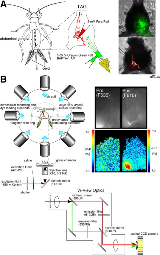
Simultaneous imaging of Ca2+ signals in the axon terminals of receptor afferents and the dendrites of a sensory interneuron. A, Diagrams showing the methods for selective loading of the different Ca2+ dyes. Left, A drawing of the cricket, Acheta domestica, shows the anatomical location of the abdominal ganglia and the connective nerve cord. A solution containing Oregon Green 488 BAPTA-1 AM at a concentration of 0.05% and a dispersing reagent (Pluronic F-127) at a concentration of 1% was pressure-injected through a glass micropipette under the sheath of cercal sensory nerve. Fura Red (2 mm) was iontophoretically injected into the dendritic branch of the cercal sensory interneurons through a glass microelectrode with a hyperpolarizing current of 3 nA for 5–10 min. Right, Superimposed displays of confocal images showing fluorescence of Oregon Green 488 BAPTA-1 loaded into the afferent axons of a left cercus (top image) or Fura Red injected into IN 10-2 (bottom image) over the transmitted light images of the TAG of the cricket. These images were acquired from different samples. B, Diagrams of the experimental setup. The top diagram is an overhead view of the stage for air-current stimulation and electrophysiological recording. The bottom diagram indicates the optical splitting system for simultaneous monitoring of two fluorescent wavelengths of Oregon Green and Fura Red. A fluorescent image was divided into two images by W-view optics with a set of dichroic mirrors and emission filters (see Materials and Methods). Both images were acquired in the same frame, side-by-side with a cooled CCD camera at the same time. Right, Raw fluorescent images (top) prestimulated and pseudocolor images (bottom) indicating the [Ca2+]i elevation in the cercal sensory afferents (left) and IN 10-3 (right) in response to air-current stimulus applied to the cerci from the anterior orientation.
Air-current stimulation.
Air-current stimuli were provided by a short puff of N2 gas from a plastic nozzle with a diameter of 13 mm. The pressure and duration of the air puff were controlled at 20 psi and 200 ms by a pneumatic picopump (PV230; World Precision Instruments, Sarasota, FL) connected to a N2 gas cylinder. Eight nozzles were arranged around the cerci on the same horizontal plane. The nozzle ends were positioned at 45° angle between each other at a distance of 20 mm from the center of TAG (Fig. 1 B).
Electrophysiology.
Intracellular recordings of the membrane potential of the IN were made using glass microelectrodes (30–50 MΩ) filled with 150 mm potassium acetate and 2 mm Fura Red. The electrode was inserted into the IN in one of the large neurites. Action potentials of INs were also monitored with a pair of hook electrodes positioned under the abdominal nerve cords (Fig. 1 B). For electrical stimulation of the sensory afferents, a train of pulses (pulse duration, 100 μs) was applied to the left or right cercal nerve with two pairs of hook electrodes. The intensity of the electrical stimulation was adjusted in the range of 3.0–4.0 V to a level that evoked action potentials in INs. All electrophysiological signals were digitized at 20 kHz through an analog-to-digital converter (Powerlab 4s; ADInstruments, Castle Hill, New South Wales, Australia) and analyzed with a Macintosh personal computer using data acquisition software (Chart version 4.2; ADInstruments).
Simultaneous optical recording of presynaptic and postsynaptic activities.
Fluorescent signals were viewed with an inverted microscope (Axiovert100; Zeiss, Oberkochen, Germany) through a 10×, 0.3 numerical aperture dry objective (Plan-Neofluar; Zeiss). A Xenon arc lamp (XBO 75 w; Zeiss) illumination with a stabilized power supply and 470/20 bandpass filter was used for excitation of the Ca2+ indicators, Oregon Green 488 BAPTA-1 and Fura Red. For simultaneous measurement of presynaptic and postsynaptic Ca2+ signals, a fluorescent image passing through an FT510 dichroic mirror was divided into two images with W-view optics (Hamamatsu Photonics, Hamamatsu, Japan) by the following filter set: dichroic 590LP; emission 535/45 for the Oregon Green and 610/25 for Fura Red (Fig. 1 B). The two separated images were simultaneously acquired side-by-side in the same frame with a digital cooled-CCD camera (ORCA-ER; Hamamatsu Photonics) attached to the inverted microscope.
A series of fluorescent images were acquired at 30 Hz on 160 × 256 pixel image for each wavelength. For the simultaneous measurement of two fluorescence wavelengths of Oregon Green and Fura Red, a software package (AQUACOSMOS/RATIO; Hamamatsu Photonics) was used. For time-course displays of the fluorescence changes in several regions of the dendritic tree, several polygonal recording regions on a Fura Red image of the INs were selected and the mean values of the fluorescent intensities in these regions were plotted as a function of time. Fluorescent intensities were collected from each fluorescent image and background corrected and averaged for each selected region. Cytosolic Ca2+ concentration ([Ca2+]i) changes were expressed as ΔF/F [ΔF/F = (F − F 0) /F 0] for Oregon Green or −ΔF/F for Fura Red, where F 0 was the background-corrected prestimulus fluorescent intensity.
Calculation of the electrotonic distance in sensory interneurons.
Electrotonic distance [log attenuation, or log(A)] was estimated using morphologically detailed compartmental models. Details concerning the morphological reconstruction, development and parameter selection of these models can be found in our previous work (Cummins et al., 2003). Briefly, passive electrophysiological parameters of the models were chosen to fit observed complex input impedance measurements in the proximal dendrites of the cells under the assumption that the dendrites were strictly passive. Active conductances in the axon were implemented as parametric models with a Hodgkin–Huxley type form, and peak conductance and rate parameters were fit to duplicate action-potential waveforms observed via capacitance-compensated intracellular recordings in real cells. Models were simulated using the Neuron simulation environment (version 5.8; http://www.neuron.yale.edu/neuron/), and the built-in tools in Neuron for constructing impedance plots were used to calculate attenuation in the models. The log(A) was calculated at 0 Hz (DC) using the V in mode of the impedance plot tool in Neuron. In this mode, the simulator calculates the attenuation of the depolarization caused by a small DC input injected at each point on the dendrite during propagation to a marked point in the model. In our models, we choose this point to be a spike-initiating zone (SIZ).
The exact location of the SIZ was determined using the following procedure: first, we calculated the voltage threshold for action-potential generation in the regions of the model with active channels. This was done by injecting short (∼1 ms) pulses of current directly into the axon compartment of the models. These pulses were increased in small steps until action potentials were evoked. The threshold value was defined to be the smallest depolarization (e.g., the most negative membrane potential) that was always followed by an action potential whenever it was attained. Second, we injected white noise currents into the proximal dendrites of the models. This stimulation was set at the lowest amplitude that evoked at least one action potential within 250 ms of simulated stimulation. During this simulation, we recorded the membrane potentials of all axon regions as a function of time. The SIZ was defined to be the location where the (previously calculated) spike threshold potential was first crossed. This location did not correspond to the electrogenic segment closest to the stimulation site, and did not vary noticeably with changes in the location of white noise current injection. If the injection site was moved to more distal locations in the dendritic tree, we needed to increase current amplitude to generate spikes, but the resulting spikes were then generated in the same location.
Obviously, the choice of the conductance and kinetic parameters for the active conductance models could result in changes to the calculated location of the SIZ. In both of the interneuron models studied here, however, the calculated location of the SIZ showed very little sensitivity to these parameters in the vicinity of the physiologically fit values. This is probably because both cells possess morphological constrictions in the proximal axon. These constrictions were included in the models, and result in a concentration of current from the dendrites that favors action- potential initiation. In both models the SIZ location was calculated in or very near this constriction for a relatively wide range of channel conductance distributions (including the parameters that best fit physiological spike data). Choosing this SIZ location is broadly consistent with existing intracellular recordings of action potentials in these cells. To our knowledge, no physiological data that would exactly establish the locations of the SIZs is available.
Results
Simultaneous imaging of presynaptic and postsynaptic Ca2+ responses to air currents
Two kinds of Ca2+ indicators with different fluorescent wavelengths were loaded to presynaptic and postsynaptic neurons, respectively. The sensory afferent fibers were stained with AM ester of Oregon Green 488 BAPTA-1, whereas Fura Red was ionophoretically injected into the IN (Fig. 1 A). Using the special optical system which separates optical signals of Oregon Green and Fura Red, we measured the Ca2+ responses to the air-current stimuli in the dendrites of the IN and in the afferent axon terminals having synaptic connections on that dendritic branch simultaneously (Fig. 1 B). It was observed that the air-current stimulus evoked significant decrease in the fluorescence of Fura Red (610 nm wavelength), which indicates an elevation in cytosolic Ca2+ concentration ([Ca2+]i) at the dendritic region of the postsynaptic IN. Simultaneous measurement of light with 535 nm wavelength at the same recording area showed a fluorescence increase of Oregon Green, indicating a rise in Ca2+ in the sensory afferents (Fig. 1 B). It has also been confirmed that there is no cross talk between the presynaptic and postsynaptic optical signals in this imaging method. Injection of depolarizing current into the IN evoked action potentials and induced a large elevation in the postsynaptic Ca2+ signal, with no change in the fluorescence of presynaptic Ca2+ indicator (supplemental Fig. 1, available at www.jneurosci.org as supplemental material). This observation demonstrates that this optical recording method makes it possible to monitor the presynaptic and postsynaptic activity independently.
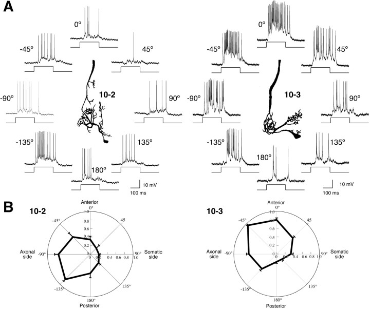
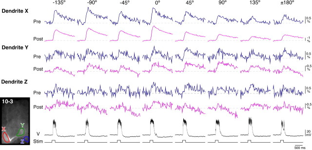
Previous studies have shown that several identified sensory interneurons, including INs 10-2 and 10-3 are directionally tuned to air-current stimuli (Bacon and Murphey, 1984; Jacobs et al., 1986; Miller et al., 1991). Intracellular recording from these INs in a preparation isolated for our optical recording experiment showed that these cells exhibited the same directional sensitivity as was observed in intact preparations (Fig. 2). Then, we recorded the presynaptic and postsynaptic local responses to the air-current stimuli on each dendrite. We applied the air-current stimuli from eight different directions in the horizontal plane, and examined the directional sensitivity in the Ca2+ responses of the sensory afferents and of the IN. Figure 3 shows typical responses to the air-current stimuli in the presynaptic and postsynaptic Ca2+ changes, which were measured at three different dendritic branches of IN 10-3. Presynaptic and postsynaptic Ca2+ responses showed directional tuning properties in their response amplitudes. It was, furthermore, observed at dendrite X that the stimulus from 0° direction induced a large Ca2+ response in the postsynaptic interneuron, and also evoked a large response in the presynaptic sensory afferents. When the postsynaptic dendrite X showed a small response to the stimulus from 180° direction, the presynaptic response to that direction was also small. This similarity in the amplitudes between the presynaptic and postsynaptic Ca2+ responses is also observed in the results of dendrites Y and Z.
Figure 2.
Directional tuning in action-potential responses to air-current stimuli in the sensory interneurons, acquired from the preparations isolated for the optical recording. A, Typical responses to air-current stimuli applied from eight different directions in INs 10-2 and 10-3. The center insets indicate camera lucida drawings of INs. The directions of stimuli from somatic side of each IN are indicated as plus degree clockwise from the anterior of the cricket. The directions of stimuli from the axonal side are indicated as minus degree counterclockwise from anterior. Bottom traces show the duration of the air-current stimuli. B, Polar plots of mean number of spikes in INs 10-2 and 10-3 versus stimulus orientation. Each value of the responses was scaled to the maximal responses of each measurement. All points in these plots represent the mean value of the scaled responses of 10 measurements in 6 different preparations of IN 10-2 or 23 measurements in 16 different preparations of IN 10-3. Error bars represent SEM of the scaled responses in different measurements. IN 10-2 has a peak sensitivity to the posteroaxonal direction (−135°), and IN 10-3 maximally responds to the anteroaxonal direction (−45°). These observations show that the cercal sensory-to-interneuron system in the isolated preparation functions normally in detecting the air-current directions as well as in intact animals.
Figure 3.
Presynaptic and postsynaptic Ca2+ responses to air-current stimuli from eight different directions in IN 10-3. The three pairs of top traces indicate the time courses of changes in ΔF/F in 535 nm wavelengths, meaning presynaptic Ca2+ signals (dark blue traces), and −ΔF/F in 610 nm wavelengths, meaning postsynaptic Ca2+ signals (magenta traces), which were measured in three different dendritic regions, X, Y, and Z, shown as ROIs in the inset of fluorescent image of IN 10-3. Second traces from the bottom (V) are membrane-potential responses of IN 10-3 intracellularly recorded simultaneously. Bottom traces show the duration of the air-current stimuli.
Directional tuning of presynaptic and postsynaptic Ca2+ signals on local dendritic regions
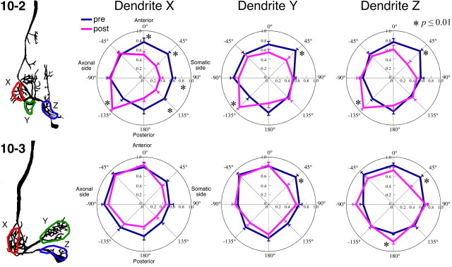
We measured the amplitude in both presynaptic and postsynaptic Ca2+ responses to these different directional stimuli in many different preparations (presynaptic responses for IN 10-2, n = 13; postsynaptic responses for IN 10-2, n = 11; presynaptic responses for IN 10-3, n = 8; postsynaptic responses for IN 10-3, n = 12). Based on these data, we analyzed the directional tuning characteristics in the presynaptic and postsynaptic activities at three different dendritic regions, X, Y, and Z, of INs 10-2 and 10-3, respectively. The response amplitudes of the Ca2+ signal at each direction were scaled by the maximum response amplitude in eight measurements of the responses to air-current stimuli from different directions in that recording region. Polar plots in Figure 4 indicate the directional tuning curves, in which mean values of the response amplitudes are plotted versus stimulus direction. In the dendrite X of IN 10-2, the presynaptic response to stimuli from 0, 45, 90, 135 and −135° directions are significantly different in their scaled amplitudes from postsynaptic responses (t test, p ≤ 0.01). However, there is no significant difference in the scaled response amplitude between presynaptic and postsynaptic Ca2+ responses in dendrite X of IN 10-3 (t test, p > 0.01).
Figure 4.
Directional tuning curves of presynaptic and postsynaptic Ca2+ responses. Polar plots indicate the mean amplitude of the air-current-evoked Ca2+ increases versus stimulus orientation. The presynaptic and postsynaptic Ca2+ signals were measured in three different dendritic regions, X, Y, and Z, of INs 10-2 (top plots) or 10-3 (bottom plots) shown in the left drawings. Each value of the Ca2+ responses was scaled to the maximal responses of each measurement. All points in the plots of IN 10-2 represent the mean value of the scaled responses of 13 measurements in 11 different preparations for presynaptic responses and 11 measurements in 7 different preparations for postsynaptic responses. All points in the plots of IN 10-3 represent the mean value of the scaled responses of 8 measurements in 6 different preparations for presynaptic responses and 12 measurements in 9 different preparations for postsynaptic responses. Error bars represent the SEM of the scaled responses in different measurements. We compared the scaled amplitudes of presynaptic and postsynaptic Ca2+ signals recorded at individual dendrites for each direction using t tests (*p ≤ 0.01). For example, the presynaptic response to stimuli from 0, 45, 90, 135, and −135° directions are significantly different from postsynaptic responses in dendrite X of IN 10-2. However, there is no difference between presynaptic and postsynaptic responses in dendrite X of IN 10-3.
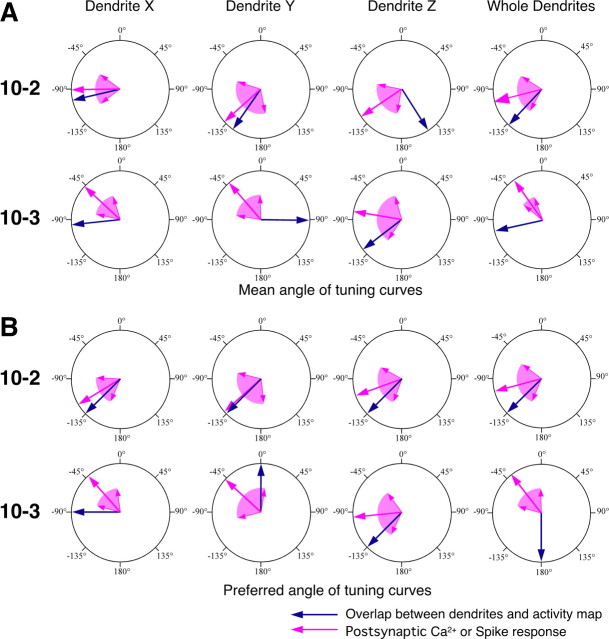
However, the statistical test for the response amplitudes to each direction might be insufficient to test the correlation between presynaptic and postsynaptic responses in their directional selective properties. In the dendrites Y and Z of IN 10-2, significant differences were obtained for only two directions, 45 and −135°, but the tuning curves of the presynaptic and postsynaptic responses clearly display opposite directional preferences from each other. We therefore used two specific parameters characterizing the directional tuning, which were “mean angle” and “preferred angle.” Based on the data of individual tuning curves, we calculated the response vector in length represented by the response amplitude and with the angle represented by the stimulus direction. The mean angle is determined as the angle of the mean vector of all response vectors obtained from eight measurements for different stimulus directions. The preferred angle is simply obtained from the direction from which the air-current stimulus evoked the maximum response in each sample. (Supplemental Fig. 2, available at www.jneurosci.org as supplemental material, indicates the histograms of the mean angle and the preferred angle of the individual tuning curves in all samples.) Here, the directional selective property is represented by the directional distribution of these two parameters. For example, the presynaptic and postsynaptic Ca2+ responses in the dendrite X of IN 10-2 are different from each other in the distribution of mean angle and preferred angle. However, the postsynaptic Ca2+ responses in the dendrite X of IN 10-3 show similar distribution to the presynaptic Ca2+ signals. Using the Watson–Williams test (Zar, 1999), the directional distributions of the mean angle and preferred angle were statistically compared between the presynaptic and postsynaptic Ca2+ responses at each dendrite of the INs (Fig. 5). In all dendritic branches of IN 10-2, both mean angle and preferred angle of directional tuning in the dendritic Ca2+ responses are significantly different from those in the presynaptic Ca2+ responses of the sensory afferents arborizing on those dendritic branches (Watson–Williams test, p ≤ 0.05). These differences in the mean angle and the preferred angle between presynaptic and postsynaptic Ca2+ responses in IN 10-2 mean that the dendritic activity in IN 10-2 does not directly reflect the directional selective property of the afferents synaptically connecting to that dendritic branch. In contrast, both of the parameters representing the directional tuning in the postsynaptic Ca2+ response in the dendrites X and Y of IN 10-3 are close to those in the presynaptic Ca2+ signals (Watson–Williams test, p > 0.05). This result suggests that the individual dendrites of IN 10-3 accurately extract distinct directional sensitivity of presynaptic activity from the sensory afferents arborizing on the dendritic branches.
Figure 5.
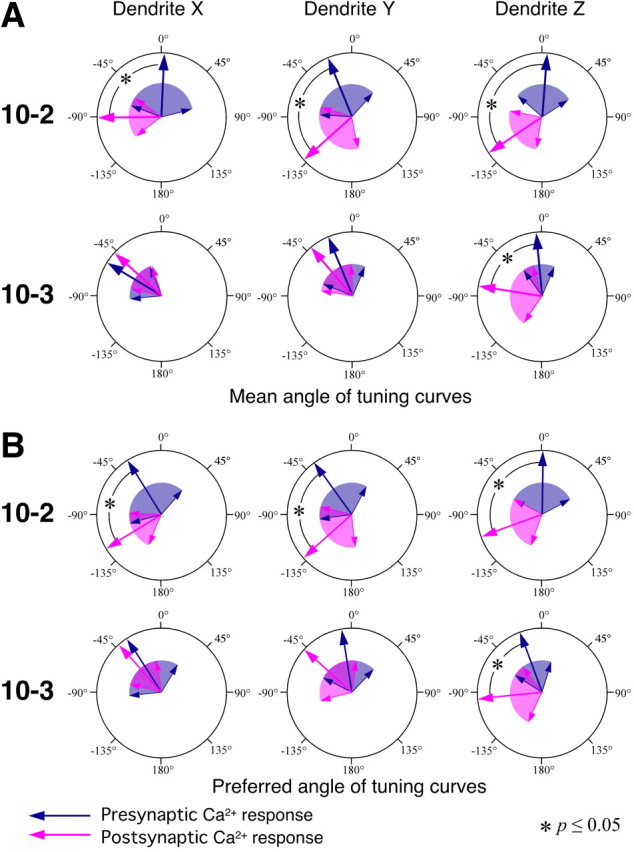
Statistical comparison of the presynaptic and postsynaptic Ca2+ responses of their directional tuning property at each dendrite of INs 10-2 and 10-3. A, B, Large arrows indicate the direction of mean vector of the data on the mean angle (A) or the preferred angle (B) in all samples shown. Colored areas wedged between smaller arrows indicate the angular deviation indicating the range of circular distribution of the data. A, Mean angles representing the directional tuning are show as presynaptic (dark blue arrow) and postsynaptic (magenta arrow) Ca2+ responses. B, Preferred angles from which the stimulus evokes the maximal response in the presynaptic (dark blue arrow) and postsynaptic (magenta arrow) [Ca2+]i changes. Both the mean angle and the preferred angle of directional tuning in the dendritic Ca2+ responses in IN 10-2 are significantly different from those in the presynaptic Ca2+ responses of the sensory afferents arborizing on those dendritic branches (Watson–Williams test, p ≤ 0.05). In the dendrites X and Y of IN 10-3, both angles of the directional tuning in the postsynaptic Ca2+ response are close to those in the presynaptic Ca2+ signals in the region occupied by that dendritic branch (Watson–Williams test, p > 0.05).
Directional distribution of active presynaptic sites on each dendritic branch and tuning curves of the dendritic Ca2+ responses of interneurons
What algorithm is used in IN 10-2 for extracting the directional tuning characteristics from the presynaptic inputs? The synaptic terminals of axons of all receptor neurons form a functional map of air-current direction (Jacobs and Theunissen, 1996; Paydar et al., 1999). A representation of the entire afferent map has been developed, based on anatomical and physiological measurements taken from a large sample of individual afferents (Troyer et al., 1994; Jacobs and Theunissen, 1996, 2000; Paydar et al., 1999). Analysis of the anatomical overlap between the predicted afferent map and the dendrites of the IN lead to a hypothesis that the INs extract their directional selective properties based on the relative position of their dendrites within the afferent map (Jacobs and Theunissen, 2000).
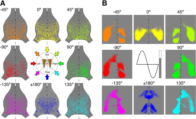
Our previous study with Ca2+ imaging visualized the spatial patterns of air-current-evoked ensemble activity of mechanosensory afferents from one-side of the cercus (Ogawa et al., 2006). In this work, we averaged ΔF/F responses in sensory afferents to 50 repeated air-current stimuli from each specific direction, and picked up the regions with a positive fluorescence change as an elevation in Ca2+ in the afferents. These regions, measured in 9–12 samples, were superimposed and the axonal Ca2+ signal was subtracted from those images. Because of this image processing, briefly summarized in the figure legend for supplemental Figure 3 (available at www.jneurosci.org as supplemental material), different spatial patterns of the afferent Ca2+ responses to stimuli from eight different directions were obtained. Based on these activity patterns in a single side of the cercal afferents, entire maps of afferent activity within the whole of TAG were reconstructed (supplemental Fig. 3, available at www.jneurosci.org as supplemental material). The entire maps of afferent-activity patterns were basically consistent with the functional maps predicted through combined anatomical and electrophysiological studies (Fig. 6) (Jacobs and Theunissen, 1996, 2000; Paydar et al., 1999). This similarity supports that direction of air currents surrounding the cricket is represented by the spatial pattern of ensemble activity in the mechanosensory afferents within the TAG.
Figure 6.
Activity pattern map and anatomically predicted map representing the direction of air currents. A, The entire map of afferent-activity patterns within whole of TAG elicited by eight different sets of directional air-current stimuli to both cerci. Each of the eight patterns were reconstructed from right and left images of activity patterns within the hemisphere of TAG. Data were acquired from 23 different animals. The center diagram indicates the corresponding stimulus direction with respect to a pair of the cerci. The color of arrows indicates the color coding for the stimulus direction. B, Dorsal view of the predictions of the spatial patterns of activity within the neural map, which were based on the previous studies (Jacobs and Theunissen, 2000). The activity level was binary imaged, >68% of the maximum level was indicated as colored area, and <68% of the maximum activity was indicated as gray. The color coding for the stimulus direction corresponds to that shown in A. The inset shows the binary color gray scale, aligned with a cosine function to represent an afferent directional tuning curve.
We examined the relative positions of the dendrites of INs 10-2 or 10-3 superimposed over the entire maps of afferent activity patterns, to test the hypothesis that the location of a dendrites within the anatomical map of the afferent projection is primary determinant of the tuning characteristics of the IN (Jacobs and Theunissen, 1996, 2000; Paydar et al., 1999). Figure 7 A shows superimposed displays of dendritic arbors (shown in red) of IN 10-2 within the afferent activity patterns (shown in green) in response to the air-current stimuli from eight different directions. Yellow spots indicate the regions where the activity patterns in the dendrites and the afferent activity overlap. It is assumed that these regions are active presynaptic sites on the dendrites of the INs in each response. The extent of the active presynaptic sites was quantified by calculating the percentage of the overlap area (Fig. 7 A, yellow) over the dimension of each dendrite or whole dendrites (Fig. 7 A, red). Thus, the bar-graphs in Figure 7 B represent the directional distributions of the mean amount of active presynaptic sites on dendrites of the interneurons. The line plots show the directional tuning curves of the dendritic Ca2+ responses for dendrites X, Y, and Z, or the voltage response for whole dendrites. Comparing the bar graphs with the line plots, it appears that directional distributions of the active presynaptic sites on dendrites of IN 10-2 are similar to the directional tuning curves of those dendritic Ca2+ responses, respectively. For quantitative analysis, we calculated the mean angle and the preferred angle representing the directional distribution of the active presynaptic sites, and compared these parameters to those for tuning properties of the postsynaptic Ca2+ or spike responses (Fig. 8).
Figure 7.
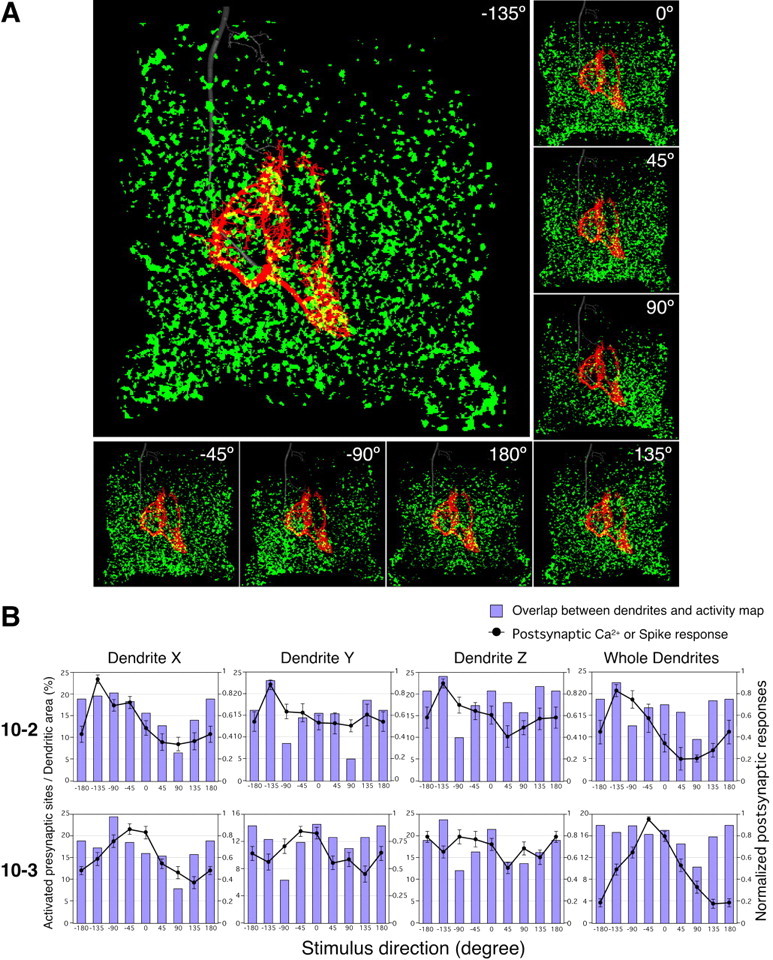
Directional distribution of the extent of active presynaptic sites on dendrites and directional tuning properties of the postsynaptic responses of interneurons. A, Superimposed displays of the whole dendritic arbor of IN 10-2 (red) over the afferent activity patterns (green) in response to eight different directional air-current stimuli. The morphological information on the dendritic arbor was based on digital reconstructions of stained INs. These reconstructions were scaled and aligned to landmarks of the ganglion. Yellow spots indicate the overlapping regions of the dendrites within the afferent activity patterns. These regions were regarded as presynaptic sites activated by the air-current stimulus from specific direction. B, Directional distribution of the extent of active presynaptic sites on dendritic branches and directional tuning curves of the dendritic Ca2+ responses or spike counts of INs 10-2 and 10-3. Each bar shows percentage of the active presynaptic sites on each dendrite or whole dendrites. Lines plotted in panels of dendrites X, Y, and Z show the directional tuning curve of the Ca2+ responses in the relevant dendrites. The line plot in the panel of whole dendrites shows the tuning curve based on spike count in INs. The data for these tuning curves plotted in Cartesian coordinate were acquired from the same measurements shown in polar plots in Figures 2 and 4. All points of the tuning curves of Ca2+ or spike responses represent the mean value of the amplitude of Ca2+ rise or the spike number scaled to the maximal responses of each measurement. Error bars represent SEM of the scaled responses in different measurements. Directional distributions of the active presynaptic sites on dendrites of IN 10-2 are similar to the directional tuning curves of those dendritic Ca2+ responses, respectively.
Figure 8.
Comparison of the directional distribution of active presynaptic sites on each dendrite of INs and directional tuning of the postsynaptic responses in that dendrite. Large magenta-colored arrows indicate the direction of mean vector of the data on the mean angle or the preferred angle that characterize the directional tuning of the postsynaptic Ca2+ or spike responses. The magenta-colored area wedged between the smaller arrows indicates the angular deviation indicating the range of circular distribution of the data about the mean angle and preferred angle. The mean angle and preferred angle representing the tuning property of dendritic Ca2+ responses were the same results as shown in Figure 6. The data for the tuning property of the spike responses were acquired from the same measurements shown in all samples in Figure 2. Large dark-blue-colored arrows in A indicate the mean angle of the directional distribution of the presynaptic active sites on each dendrite, and those in B indicate the preferred angle from which the stimulus activates the broadest presynaptic sites on that dendrite. These mean angles and preferred angles represent statistical values representing the directional distribution of the active presynaptic sites, because the entire map of the afferent activity patterns used for measurement of the overlap on dendrites were built from a sum of 9–12 different samples for each direction. A, Mean angles of the directional distributions of active presynaptic sites on the dendrites (dark blue arrow) and the mean angle representing the directional tuning of the postsynaptic responses (magenta arrow). B, Preferred angles from which the stimulus activated the broadest presynaptic sites on each dendrite (dark blue arrow) and the preferred angle from which the stimulus evoked the maximal response in the dendritic [Ca2+]i change or the action-potential firing (magenta arrow). Both of the mean angles and the preferred angles in directional distribution of the active presynaptic sites are close to those of directional tuning in the postsynaptic responses of IN 10-2, except for the results of mean angle in dendrite Z. In the dendrites X and Y and whole dendrites of IN 10-3, both angles in the directional distribution of the active presynaptic sites are different from those representing the directional tuning in the postsynaptic responses.
Both of the mean angles and the preferred angles of the directional distribution of the active presynaptic sites on dendrites X and Y of IN 10-2 approximated to those of directional tuning of the Ca2+ responses in those dendrites (Fig. 8 A,B, top series). These results demonstrate that directional profiles of the presynaptic sites over the dendrites correspond to the directional tuning curves of the dendritic Ca2+ responses in IN 10-2. It is supposed that the amount of active presynaptic sites on each dendrite of IN 10-2 could determine the directional selective property of that dendrite. Furthermore, the directional distribution of the active presynaptic sites on whole dendrites of IN 10-2 also showed a closer mean angle and preferred angle to those of the tuning curve of the spiking response. This result means that the directional profile of the overlap of the dendrites of IN 10-2 with the afferent activity patterns correlates with the directional tuning of spike responses as the final output of IN 10-2. These results obtained in IN 10-2 directly support the hypothesis described above, that the directional tuning property of the IN can be explained primarily on the basis of the overlap between its dendrites and afferent activity maps. However, the directional distributions of the active presynaptic sites on the dendrites of IN 10-3 were different in their mean angle and preferred angle from the directional tuning curves of the dendritic Ca2+ responses or spike response (Fig. 8 A,B, lower series). This result suggests that the amount of overlap of the activated presynaptic sites over the dendrites has indecisive influence on the directional tuning property of IN 10-3.
Summarizing both results in Figures 5 and 8 suggests that the decoding algorithm used for the extraction of the directional tuning properties could be different between IN 10-2 and IN 10-3. Whereas the whole dendrites of IN 10-2 extract the stimulus direction represented by the spatial pattern of ensemble activity within the sensory-afferent projection, the individual dendrites of IN 10-3 could extract distinct directional sensitivity encoded by local presynaptic activity of the sensory afferents occupied by that dendritic branch. Here, the following question arises: why is IN 10-2 different from IN 10-3 in its algorithm for the extraction of directional sensitivity? We assumed that their dendritic geometries might be related to that difference of the decoding algorithm, because geometry of the dendritic tree is one of the essential factors known to be important in dendritic information processing.
Relationship between electrotonic geometry of dendrites and decoding algorithm for extraction of directional selective property
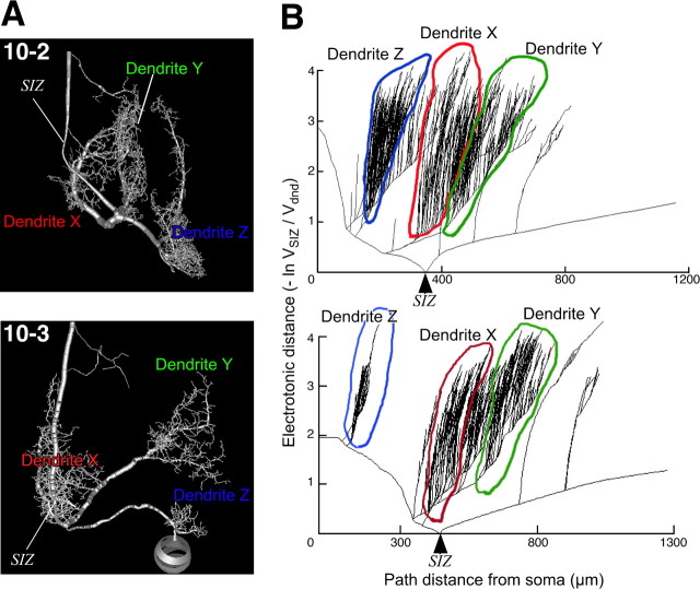
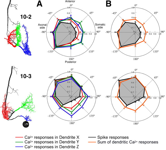
We calculated inward electrotonic distances (EDs) from the dendrites to an SIZ, based on compartmental models of INs 10-2 and 10-3 (Fig. 9 A) (for details of the modeling, see Materials and Methods). Figure 9 B shows plots of a log attenuation of depolarizing voltages during propagation from various points on the dendrites of INs 10-2 and 10-3 to their respective SIZ compartments. We focused on the variation of EDs from main three branches of dendrites in INs 10-2 and 10-3 to SIZs. In IN 10-2, EDs from each dendrite to SIZ are almost the same as each other (Fig. 9 B, top). This result suggests that synaptic inputs received at all dendritic branches could be weighted equally. Therefore, the directional selective properties extracted by different dendritic branches would contribute equally to the overall tuning in IN 10-2. In fact, the tuning curves of dendritic Ca2+ responses in IN 10-2 were similar to each other (Fig. 10 A). Furthermore, the tuning curve, predicted by calculating the weighted sum of the tuning curves of the individual dendritic responses based on EDs, is approximated the directional profile of the spike counts (Fig. 10 B).
Figure 9.
Electrotonic geometry of the dendritic arbor of the INs. A, Images showing the compartment models of INs 10-2 and 10-3 with the SIZ indicated. B, Plots of inward ED versus path distance relative to the SIZ in the IN models. The ED was shown as the log attenuation of depolarizing voltages during propagation from various points on the dendrites to the SIZ of the compartment models. Attenuation is defined as the ratio of voltage at the site of injection to voltage at the SIZ (see Materials and Methods). The x-axis is the path distance from the soma to the compartment along each process. In IN 10-2, the EDs from each dendrite to the SIZ are almost the same as each other, whereas the EDs from each dendrite to the SIZ in IN 10-3 vary from each other.
Figure 10.
Directional tuning curves of dendritic Ca2+ responses and action-potential responses in the INs. A, Polar plots indicate the mean number of spikes (black line) and the mean amplitude of Ca2+ increases at three different dendrites, X, Y, and Z (red, green, and blue lines, respectively). The presynaptic and postsynaptic Ca2+ signals were measured in three different dendritic regions, X, Y, and Z, of INs 10-2 (top) or 10-3 (bottom) shown in the left images. Each value of the Ca2+ and action-potential responses was scaled to the maximal responses of each measurement. Error bars represent SEM of the scaled responses in different measurements. The data for the tuning curves were acquired from the same measurements shown in Figures 2 and 4. The tuning curves of dendritic Ca2+ responses in IN 10-2 showed similar directional profiles to each other, whereas in IN 10-3, the tuning curve of dendrite X is more similar to the curve of the spike response than that of the other dendrites. B, Directional tuning curves as measured by spike count (black lines) and the curve (orange lines) predicted by calculating the weighted sum of the tuning curves of the individual dendritic responses based on electrotonic distances. Each value of the dendritic tuning curve for the summation was weighted as a function of normalized value of the attenuation (A) (see Materials and Methods), which is V SIZ (voltage at the SIZ)/V dnd (voltage at the branch point of each dendrite). The attenuations measured at 0 Hz are as follows: 0.56 for dendrite X, 0.47 for dendrite Y, and 0.325 for dendrite Z of IN 10-2; and 0.82 for dendrite X, 0.172 for dendrite Y, and 0.36 for dendrite Z of IN 10-3.
However, the EDs from each dendrite to the SIZ in IN 10-3 vary. The log attenuation of the depolarizing voltage at the dendrite X is much smaller than the other dendrites Y and Z (Fig. 9 B). This result suggests that the directional sensitivity of the nearest dendrite X to SIZ dominates the tuning properties of spike counts in IN 10-3. Actually, the tuning curve of the dendrite X is most analogous to the curve of the spiking response (Fig. 10 A). Even more amazingly, the curve of dendrite X is closer to the overall tuning than the curve predicted from the weighted sum of dendritic responses (Fig. 10 B). This result means that IN 10-3 could selectively extract the directional tuning property of the synaptic inputs received at the dendrite X. It is supposed that the algorithm for decoding of the directional selective sensitivity may reflect the differences in distribution of synaptic weights because of the dendritic geometry of the postsynaptic sensory interneurons.
Discussion
While sensory information is encoded by the firing pattern of individual sensory neurons, it is also represented by spatiotemporal patterns of activity in the populations of the neurons. In the cricket cercal sensory system, the direction of air currents surrounding the cricket is encoded by the firing patterns of individual mechanosensory neurons (Landolfa and Miller, 1995); meanwhile, it is also represented by the spatial patterns of ensemble activity in the sensory afferents (Troyer et al., 1994; Jacobs and Theunissen, 1996, 2000; Paydar et al., 1999). Postsynaptic INs must decode the individual or collective response patterns of presynaptic mechanosensory neurons to extract directional information as reliably as possible. According to the encoding behavior of the sensory information, the INs may implement two different types of decoding algorithms on their dendrites. The first is that the entire dendritic tree decodes the population-represented direction as the total amount of synaptic inputs. The other is that the directional sensitivity encoded by amplitude of individual synaptic inputs is directly extracted by each dendritic branch, and that the distinct response properties of different dendrites are integrated in the process of spike initiation. Simultaneous imaging of presynaptic and postsynaptic Ca2+ signals enables us to determine which type of decoding algorithm is performed by the cercal sensory interneurons.
The analysis of the directional tuning properties of presynaptic and postsynaptic activities and the identification of the relative position of the dendrites of the INs within the activity map representing the air-current direction lead to different results INs 10-2 and 10-3. IN 10-2 extracts the directional tuning property represented by the amount of active presynaptic sites overlapping its dendrites (Fig. 8), meaning that IN 10-2 would adopt the first type of decoding algorithm. This result is consistent with the hypothesis proposed by anatomical overlap in previous study (Jacobs and Theunissen, 2000). In IN 10-2, furthermore, the mismatch between the tuning curves of the presynaptic and postsynaptic Ca2+ signals detected at each dendrite (Fig. 5) suggests that IN 10-2 will also receive a small amount of synaptic input from sensory afferents, whose preferred direction is different from that of IN 10-2.
However, individual dendrites of IN 10-3 extracts the distinct tuning property directly from the sensory afferents arborizing on that dendrite (Fig. 5), meaning that IN 10-3 could adopt the second type of decoding algorithm. The preferred direction of each dendrite nearly corresponds to that estimated from the anatomical relationship between each dendrite of IN10-3 and the projection maps of afferent in the previous study (Paydar et al., 1999). Each dendrite of IN 10-3 could have synaptic connections, with only a subset of the afferents having the specific directional sensitivity. As shown in Figure 10 A, the directional tuning curves of three dendrites of IN 10-3 are more distinct in their shapes from each other than those of the dendrites of IN 10-2. The individual dendrites with different tuning properties in their Ca2+ responses are likely to receive synaptic inputs from different subsets of the afferents having different sensitivity to direction. Distinct directional sensitivity profiles extracted by each dendrite of IN 10-3 could be integrated into the overall tuning properties encoded by firing patterns in IN 10-3. The different sensitivity in local dendritic Ca2+ responses to sensory stimuli has been observed in nonspiking visual interneurons in vertebrate (Euler et al., 2002) and invertebrate (Single and Borst, 1998). In these interneurons, like IN 10-3, it has been proposed that local regions of their dendritic arbor receive synaptic inputs encoding distinct directional selectivity or receptive field to visual motion stimuli.
The surprising result is that INs 10-2 and 10-3 are likely to use different types of “decoding algorithms” for extraction of their directional sensitivity to the air current. Both types of INs have similar response properties such as velocity threshold, velocity sensitivity curve, and frequency sensitivity range (Kanou and Shimozawa, 1984; Chiba et al., 1992; Theunissen et al., 1996). Right–left INs 10-2 and 10-3 have bilaterally symmetrical directional tuning curves, each of which could be fit by a truncated cosine wave with 360° period, and of which peak sensitivity points are placed at 90° intervals around the stimulus range (Miller et al., 1991). Based on these facts, it has been proposed that INs 10-2 and 10-3 could be grouped into the same class of neurons making up an all-direction, low-velocity detecting system (Theunissen et al., 1996). In addition to these similarities of response properties and cell function, there is little difference between INs 10-2 and 10-3 in the output of their presynaptic elements and transmission characteristics of the input synapses. Both INs receive direct cholinergic excitatory synaptic inputs from the afferents of low-frequency sensitive mechanoreceptor hairs on both sides of cerci (Meyer and Reddy, 1985).
Nevertheless, why do the decoding algorithms vary between INs 10-2 and 10-3? Passive compartmental modeling of INs 10-2 and 10-3 demonstrated the difference in their dendritic geometries, which is one of the important factors for dendritic processing. In IN 10-2, EDs from each dendrite to SIZ are almost the same as each other, suggesting that synaptic currents evoked at three dendrites could equally contribute to spike generation. The decoding strategy used by an “equally weighted type” of neuron like IN 10-2 may be that whole dendrites extract “homologous” response properties about the stimulus direction represented by the population activity of presynaptic elements. However, in IN 10-3, where synaptic inputs are located at various EDs from each dendritic branch to the SIZ, it is more effective for its directional tuning to be accurately extracted by the nearest dendrite to the SIZ. The difference in the directional sensitivity among the three dendrites, X, Y, and Z, has been predicted by previous studies using selective stimulation of the mechanoreceptors and laser ablation of individual dendrites (Jacobs and Miller, 1985). For the “biased-weighted type” of neuron like IN 10-3, the other algorithm, in which the dominate dendrite correctly extracts the directional sensitivity encoded by the firing rate of individual or small groups of presynaptic elements, may be strategic. Patches of the afferent projection in the anatomical map of the cricket cercal system vary in their size depending on the stimulus direction, and are arranged three-dimensionally and intricately (Jacobs and Theunissen, 1996; Paydar et al., 1999). To extract the stimulus direction represented by this complex spatial map, therefore, there may be characteristics of the dendritic architecture for different sensory interneurons that may necessitate the implementation of different types of decoding algorithms.
This study demonstrates that either the tuning properties of the presynaptic elements or the amount of synaptic input to the dendrites are the primary determinants of directional sensitivity of the cercal sensory interneurons. However, the tuning curves predicted from the weighted sum of the tuning curves of the individual dendritic responses, showed wider sensitivity than the tuning curve based on spike count (Fig. 10 B). Shaping of the directional tuning properties in the process of dendritic integration can be caused by other factors, including inhibitory inputs from local interneurons (Levine and Murphey, 1980; Jacobs et al., 1986) and voltage-dependent conductances in the dendrites of the INs (Kloppenburg and Hörner, 1998). It is possible that the dendrite Z of IN 10-3 could receive the inhibitory inputs for trimming of the tuning curve, because the Ca2+ response in dendrite Z of IN 10-3 showed a significant difference in directional selectivity from the presynaptic responses unlike dendrite X and Y (Fig. 5). In addition, most of the source of the dendritic Ca2+ elevation in the cricket cercal sensory interneurons including IN 10-2 and 10-3 is Ca2+ influx through the voltage-gated channels (Ogawa et al., 2000). If voltage-dependent channels are heterogeneously distributed on the dendrites, the active dendrites could be involved in supralinear summation of the input conductances and complex processing of sensory information.
Footnotes
This work was supported in part by Grants-in-Aid for Scientific Research 16570068 and 19570073 from the Japan Ministry of Education, Culture, Sports, Science and Technology and the Narishige Zoological Science Award to H.O. We thank John Miller for valuable discussion and critical reading of this manuscript.
References
- Bacon JP, Murphey RK. Receptive fields of cricket giant interneurones are related to their dendritic structure. J Physiol (Lond) 1984;352:601–623. doi: 10.1113/jphysiol.1984.sp015312. [DOI] [PMC free article] [PubMed] [Google Scholar]
- Borst A, Egelhaaf M. Dendritic processing of synaptic information by sensory interneurons. Trends Neurosci. 1994;17:257–263. doi: 10.1016/0166-2236(94)90009-4. [DOI] [PubMed] [Google Scholar]
- Chiba A, Kämper G, Murphey RK. Response properties of interneurons of the cricket cercal system are conserved in spite of changes in peripheral receptors during maturation. J Exp Biol. 1992;164:1–22. [Google Scholar]
- Cummins GI, Crook SM, Dimitrov AG, Ganje T, Jacobs GA, Miller JP. Structual and biophysical mechanisms underlying dynamic sensitivity of primary sensory interneurons in the cricket cercal sensory system. Neurocomputing. 2003;52–54:45–52. [Google Scholar]
- Euler T, Detwiler PB, Denk W. Directionally selective calcium signals in dendrites of starburst amacrine cells. Nature. 2002;418:845–852. doi: 10.1038/nature00931. [DOI] [PubMed] [Google Scholar]
- Jacobs GA, Miller JP. Functional properties of individual neuronal branches isolated in situ by laser photoinactivation. Science. 1985;228:344–346. doi: 10.1126/science.3983633. [DOI] [PubMed] [Google Scholar]
- Jacobs GA, Theunissen FE. Functional organization of a neural map in the cricket cercal sensory system. J Neurosci. 1996;16:769–784. doi: 10.1523/JNEUROSCI.16-02-00769.1996. [DOI] [PMC free article] [PubMed] [Google Scholar]
- Jacobs GA, Theunissen FE. Extraction of sensory parameters from a neural map by primary sensory interneurons. J Neurosci. 2000;20:2934–2943. doi: 10.1523/JNEUROSCI.20-08-02934.2000. [DOI] [PMC free article] [PubMed] [Google Scholar]
- Jacobs GA, Miller JP, Murphey RK. Cellular mechanisms underlying directional sensitivity of an identified sensory interneuron. J Neurosci. 1986;6:2298–2311. doi: 10.1523/JNEUROSCI.06-08-02298.1986. [DOI] [PMC free article] [PubMed] [Google Scholar]
- Kanou M, Shimozawa T. A threshold analysis of cricket cercal interneurons by a alternating air-current stimulus. J Comp Physiol A Neuroethol Sens Neural Behav Physiol. 1984;154:357–365. [Google Scholar]
- Kloppenburg P, Hörner M. Voltage-activated currents in identified giant interneurons isolated from adult crickets Gryllus bimaculatus . J Exp Biol. 1998;201:2529–2541. doi: 10.1242/jeb.201.17.2529. [DOI] [PubMed] [Google Scholar]
- Landolfa MA, Miller JP. Stimulus-response properties of cricket cercal filiform receptors. J Comp Physiol A Neuroethol Sens Neural Behav Physiol. 1995;177:749–757. [Google Scholar]
- Levine RB, Murphey RK. Pre- and postsynaptic inhibition of identified giant interneurons in the cricket (Acheta domesticus) J Comp Physiol A Neuroethol Sens Neural Behav Physiol. 1980;135:269–282. [Google Scholar]
- Meyer MR, Reddy GR. Muscarinic and nicotinic cholinergic binding sites in the terminal abdominal ganglion of the cricket (Acheta domesticus) J Neurochem. 1985;45:1101–1112. doi: 10.1111/j.1471-4159.1985.tb05529.x. [DOI] [PubMed] [Google Scholar]
- Miller JP, Jacobs GA, Theunissen FE. Representation of sensory information in the cricket cercal sensory system. I. Response properties of the primary interneurons. J Neurophysiol. 1991;66:1680–1689. doi: 10.1152/jn.1991.66.5.1680. [DOI] [PubMed] [Google Scholar]
- Ogawa H, Baba Y, Oka K. Dendritic Ca2+ transient increase evoked by wind stimulus in the cricket giant interneuron. Neurosci Lett. 1999;275:61–64. doi: 10.1016/s0304-3940(99)00744-2. [DOI] [PubMed] [Google Scholar]
- Ogawa H, Baba Y, Oka K. Spike-dependent calcium influx in dendrites of the cricket giant interneuron. J Neurobiol. 2000;44:45–56. doi: 10.1002/1097-4695(200007)44:1<45::aid-neu5>3.0.co;2-#. [DOI] [PubMed] [Google Scholar]
- Ogawa H, Baba Y, Oka K. Directional sensitivity of dendritic calcium responses to wind stimuli in cricket giant interneurons. Neurosci Lett. 2004;358:185–188. doi: 10.1016/j.neulet.2004.01.023. [DOI] [PubMed] [Google Scholar]
- Ogawa H, Cummins GI, Jacobs GA, Miller JP. Visualization of ensemble activity patterns of mechanosensory afferents in the cricket cercal sensory system with calcium imaging. J Neurobiol. 2006;66:293–307. doi: 10.1002/neu.20220. [DOI] [PubMed] [Google Scholar]
- Paydar S, Doan CA, Jacobs GA. Neural mapping of direction and frequency in the cricket cercal system. J Neurosci. 1999;19:1771–1781. doi: 10.1523/JNEUROSCI.19-05-01771.1999. [DOI] [PMC free article] [PubMed] [Google Scholar]
- Single S, Borst A. Dendritic integration and its role in computing image velocity. Science. 1998;281:1848–1850. doi: 10.1126/science.281.5384.1848. [DOI] [PubMed] [Google Scholar]
- Theunissen F, Roddey JC, Stufflebeam S, Clague H, Miller JP. Information theoretic analysis of dynamical encoding by four primary sensory interneurons in the cricket cercal system. J Neurophysiol. 1996;75:1345–1376. doi: 10.1152/jn.1996.75.4.1345. [DOI] [PubMed] [Google Scholar]
- Troyer TW, Levin JE, Jacobs GA. Construction and analysis of a data base representing a neural map. Microsc Res Tech. 1994;29:329–343. doi: 10.1002/jemt.1070290502. [DOI] [PubMed] [Google Scholar]
- Zar JH. Biostatistical analysis. Ed 4. Upper Saddle River, NJ: Prentice-Hall; 1999. [Google Scholar]


