

Abstract
For visual orientation and course stabilization, flies rely heavily on the optic flow perceived by the animal during flight. The processing of optic flow is performed in motion-sensitive tangential cells of the lobula plate, which are well described with respect to their visual response properties and the connectivity among them. However, little is known about the postsynaptic descending neurons, which convey motion information to the motor circuits in the thoracic ganglion. Here we investigate the physiology and connectivity of an identified premotor descending neuron, called DNOVS2 (for descending neuron of the ocellar and vertical system). We find that DNOVS2 is tuned in a supralinear way to rotation around the longitudinal body axis. Experiments involving stimulation of the ipsilateral and the contralateral eye indicate that ipsilateral computation of motion information is modified nonlinearly by motion information from the contralateral eye. Performing double recordings of DNOVS2 and lobula plate tangential cells, we find that DNOVS2 is connected ipsilaterally to a subset of vertical-sensitive cells. From the contralateral eye, DNOVS2 receives input most likely from V2, a heterolateral spiking neuron. This specific neural circuit is sufficient for the tuning of DNOVS2, making it probably an important element in optomotor roll movements of the head and body around the fly's longitudinal axis.
Keywords: motion detection, insect, vision, descending, gap junction, flow field
Introduction
Flying animals rely heavily on visual cues to control chasing, cruising, and landing behavior (Borst and Bahde, 1988; Frye and Dickinson, 2001; Srinivasan and Zhang, 2004). In the blowfly, panoramic and small-field visual stimuli elicit optomotor movements of the head and body that attempt to stabilize the visual input on the retina (Hengstenberg, 1984, 1988, 1991). The processing of optic flow is performed in the third visual neuropil, the lobula plate. There, ∼60 lobula plate tangential cells (LPTCs) per brain hemisphere selectively integrate motion signals provided by local, columnar elements arranged in a retinotopic manner (Borst and Egelhaaf, 1992; Haag et al., 1992; Single and Borst, 1998). LPTCs can be identified individually because of their invariant anatomy and characteristic visual response properties (Hausen, 1982; Hengstenberg et al., 1982; Borst and Haag, 2002). Among them, cells of the vertical system (VS cells) respond preferentially to vertical motion, whereas cells of the horizontal system (HS cells) are best excited by horizontal motion. In addition to the columnar input, many tangential cells receive input from other tangential cells (Hausen, 1984; Horstmann et al., 2000; Haag and Borst, 2001, 2002, 2003, 2004, 2005, 2007; Farrow et al., 2003, 2005, 2006; Kalb et al., 2006). Together with the directionally selective input from columnar elements, these lobula plate network interactions are responsible for the tangential cell tuning to specific flow fields (Krapp and Hengstenberg, 1996; Krapp et al., 1998; Franz and Krapp, 2000; Karmeier et al., 2003; Cuntz et al., 2007). Although LPTCs have been studied extensively, much less is known about the descending neurons postsynaptic to LPTCs, which project via the cervical connective into the thoracic ganglion.
The anatomy of descending neurons has been investigated mainly by cobalt backfills from the cervical connective (Strausfeld and Bassemir, 1985; Strausfeld and Seyan, 1985; Gronenberg and Strausfeld, 1991). Three descending neurons, belonging to a group of Y-shaped descending neurons called DNOVS (for descending neurons of the ocellar and vertical system), were found that showed cobalt coupling to neck motor neurons of the frontal nerve and to LPTCs. Ocelli are light-sensitive organs on the dorsal surface of the head and appear to be suited for detecting changes in overall brightness (Schuppe and Hengstenberg, 1993). The physiology and connectivity of DNOVS1 was described recently (Haag et al., 2007).
In the following, we present the physiological response characteristics of DNOVS2 (also called DNDC1–2 by Gronenberg et al., 1995). Gronenberg et al. (1995) showed that the neuron responds to light ON, to antennal air currents, and to visual motion and is biocytin coupled to neck motor neurons, which mediate head rotation (Strausfeld et al., 1987; Gilbert et al., 1995). Here we demonstrate that DNOVS2 is specifically connected to LPTCs and tuned in a supralinear way to rotation around the longitudinal body axis.
Materials and Methods
Preparation and setup.
Three- to 10-d-old female blowflies (Calliphora vicina) were briefly anesthetized with CO2 and mounted ventral side up with wax on a small preparation platform. The thorax was opened from behind to get access to the connective. The fly muscles and intestinal organs were pulled out. To minimize movements of the connective, the legs were cut away, and the abdominal region was waxed. After alignment of the fly with reference to their deep pseudopupil, it was mounted on a heavy recording table facing three stimulus monitors. To stabilize the intracellular recordings, the connective was lifted up by a hook. For double recordings, the head capsule was opened from behind, and the trachea and air sacs that normally cover the lobula plate were removed. The connective was viewed from behind through a fluorescence stereomicroscope (MZ FLIII; Leica, Nussloch, Germany).
Visual stimulation.
Visual stimuli were presented on three Tektronix (Wilsonville, OR) cathode ray tube monitors (width, 10 cm; height, 13 cm). With 0° azimuth in front of the fly, monitor 1 was placed in front of the left eye and extended from −90° to −30° in azimuth and from +40° to −30° in elevation; monitor 2 was placed in front of the right eye at an azimuth position of −15° to +40°, monitor 3 was at azimuth position 55° to 120° (see Fig. 2a,b). As seen by the fly, the three monitors together covered an azimuth of 210°. For measuring the sensitivity along the azimuth (see Fig. 2), each monitor screen was divided into five stripes, each with a horizontal extent of 11° to 13°. The same stripe width was used for measuring the response to stimulus combinations shown in Figure 7. For all other experiments, we presented motion over the full monitor screen. The positions of the monitors were fixed at the positions indicated in Figure 2, and we recorded from either the right or the left DNOVS2. For the stimulus combinations in Figures 3 and 4, we presented vertical motion in two monitors, first individually and then simultaneous combinations of vertical motion in both. The asymmetric monitor positions resulted in different azimuth positions of the stimulus for the right and left DNOVS2. To avoid confusion, we mirrored all responses of the left DNOVS2. Thus, the responses for different stimulus situations are presented below as if they had been obtained from the right DNOVS2. Accordingly, we refer to the right brain hemisphere as the ipsilateral side and to the left hemisphere as the contralateral side. With this asymmetric monitor configuration, we received six axes of rotation (see Fig. 4), with poles of rotation at −42°, −22°, −12°, 12°, 22°, and 42°. To mimic a rotation around a longitudinal body axis (pole of rotation at 0°), we placed one monitor in front of the ipsilateral eye and one in front of the contralateral eye with mirror symmetric azimuth position from 20° to 75°. Stimulus pattern was moved for 1 s, followed by 1 s of rest. The pattern consisted of a square-wave grating with a spatial wavelength of 25°, produced by an image synthesizer (Picasso; Innisfree, Cambridge, MA) at a frame rate of 200 Hz. The image synthesizer was controlled by a Pentium III personal computer (PC) via a DDA06 board (ComputerBoards, Middleboro, MA). The pattern moved at a speed of 42°/s, corresponding to a temporal frequency of 1.7 Hz. The pattern contrast was 95%. The mean luminance was 12 cd/m−2. The stimulation and acquisition software was written in Delphi (Borland, Buffalo, NY).
Figure 2.

Intracellular recording from DNOVS2. Top view (a) and frontal schematic drawing (b) of the stimulus situation. c, Example response of DNOVS2 to full field downward and upward motion in all three monitors. The cell responds to downward motion with an increase of the spike frequency and to upward motion with a slight decrease of the spike frequency. d, Response of DNOVS2 to vertical motion as a function of the azimuth position. The highest responses to vertical motion are elicited at two positions of the azimuth: at a frontal position (10°) and a lateral position (75°) with downward motion increasing the spike rate and upward motion decreasing the spike rate. The mean firing rate at rest is 5–15 Hz and is increased by 88 Hz at the positions with highest response. In between, the response is less with a local minimum at 35° and an increase of the firing rate by 55 Hz. Data represent the mean ± SEM recorded from n = 7 flies.
Figure 7.
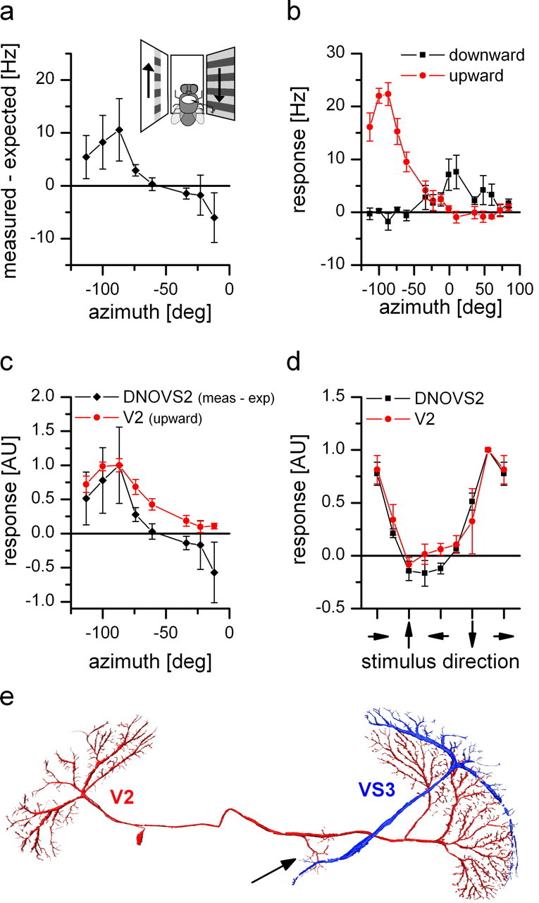
Response properties and anatomy of V2. a, Nonlinear summation of DNOVS2 as a function of the azimuth (black line). The difference between the measured response and the arithmetic sum of DNOVS2 for ipsilateral downward and contralateral upward motion is calculated for different azimuth positions. The contralateral stimulus was presented in 12° wide stripes at different position along the azimuth. At more lateral positions, the measured response of DNOVS2 is higher than the arithmetic sum, which indicates a supralinear integration. In contrast, for more frontal positions, the response of the cell is less than the arithmetic sum, indicating a sublinear integration. The highest nonlinearity was elicited at azimuth position of −87°. Data represent the mean value recorded from n = 2 flies. b, Response of V2 to vertical motion as a function of the azimuth position. The highest responses to vertical motion is elicited at lateral stimulus positions at approximately −87° in which upward motion increased the firing rate of the cell. In addition, V2 responds to motion in the frontal part with an inversed preferred direction. Data represent the mean value recorded extracellularly from n = 5 flies. Error bars represent the SEM. c, Overlay of the normalized sensitivity of V2 for upward motion (red) and the normalized nonlinearity profile of DNOVS2 (black) along the azimuth. The curves have a similar shape with a peak at the same azimuth position. AU, Arbitrary units. d, Orientation tuning of V2 (red) and DNOVS2 (black) in the frontal part of the visual field. The response normalized to the maximum response as a function of the stimulus direction is shown. The tuning curves of DNOVS2 and V2 are almost identical with a response maximum for oblique motion down to the right. Data represent the mean ± SEM of V2 (n = 4; extracellular), DNOVS2 (n = 3; 1 × intracellular + 2 × extracellular). e, Anatomy of V2. V2 and VS3 cells were filled intracellularly with the fluorescent dye Alexa 488 or Alexa 568, respectively. V2 is a heterolateral neuron projecting from one lobula plate to the other with en passant collateral to the terminal region of VS cells (arrow).
Figure 3.

Response of DNOVS2 to simultaneous motion in two sectors of the receptive field. The schematic drawings are indicating the stimulus situation. Black columns show the measured response to simultaneous motion in the ipsilateral and contralateral monitor, and gray columns indicate the algebraic sum of the responses to individual stimuli. The arrows on the x-axis represent the visual stimulus combination. The left arrow represents contralateral motion, and the right arrow represents ipsilateral motion. The arrowhead indicates the direction of motion. The neuron responds best to a rotation-like stimulus consisting of upward motion in the contralateral and downward motion in the ipsilateral field of view (penultimate stimulus configuration) with an axis of rotation at −12° (indicated in the first drawing). The response to this rotational-like stimulus is stronger than the response to downward motion in both monitors (fifth stimulus situation). This indicates that DNOVS2 responds to a rotational flow field stronger than to a translational one. In addition, for the rotational-like stimulus, the measured response is significantly higher than the arithmetic sum of the responses to individual stimuli (★ indicates p < 0.05, Wilcoxon signed-rank test). Data represent the mean ± SEM from n = 7 flies.
Figure 4.

Tuning of DNOVS2 to a rotation-like optic flow around a longitudinal body axis. The responses of DNOVS2 to clockwise rotational-like optic flow at seven different monitor positions, each representing a different axis of rotation, is shown. This results in seven different axis of rotation, with angular separations from the midline: −42°, −22°, −12°, 0°, 12°, 22°, and 42°. Clockwise rotation around a longitudinal axis (0°) elicited the strongest response in DNOVS2. The measured response is significantly stronger than the arithmetic sum of the individual components. In contrast, the response to a rotation around an axis at 42° to the right is significantly less than the expected one. The clockwise, rotatory stimulus corresponds to a counterclockwise rotation as egomotion (indicated by the arrows). Data represent the mean ± SEM from n number of flies for each axis as follows: −42° (n = 4); −22° (n = 3); −12° (n = 7); 0° (n = 3); 12° (n = 3); 22° (n = 4); and 42° (n = 8).
Electrical recordings.
For intracellular recordings, glass electrodes were pulled on a Flaming/Brown micropipette puller (model P-97; Sutter Instruments, Novato, CA), using thin-walled glass capillaries with an outer diameter of 1 mm (GC100TF-10; Clark Electromedical Instruments, Pangbourne, UK). The tip of the electrode was filled with either 10 mm Alexa Fluor 488 hydrazide (Alexa 488) or 10 mm Alexa Fluor 568 hydrazide (Alexa 568) (both from Invitrogen, Carlsbad, CA). Alexa 488 and Alexa 568 fluoresce as green and red, respectively, allowing us to identify more than one cell at a time. For Neurobiotin staining, the tip of the electrode was filled with a mixture of 3% Neurobiotin (Vector Laboratories, Burlingame, CA) and 3% fluorescein (Invitrogen). The shaft of the electrode was filled with 2 m KAc plus 0.5 m KCl. The electrodes had resistances between 15 and 35 MΩ. Recorded signals were amplified using an SEL10 amplifier (NPI Electronic, Tamm, Germany). The output signals of the amplifier were fed to a Pentium III PC via a 12-bit analog-to-digital converter (DAS-1602; ComputerBoards) at a sampling rate of 5 kHz. Recordings of DNOVS2 were made in the connective near the thoracic ganglion. DNOVS2 was identified based on its anatomy compared with the other DNOVS cells (Fig. 1) (Strausfeld and Bassemir, 1985). VS cells were recorded from the axon and were identified using a method described by Farrow (2005). There, not only the characteristic anatomy of the cell was taken into account but also the relative position of their ventral dendrite within the lobula plate. V2 was recorded in its axonal arborization and could be identified because of its invariant anatomy (Hausen, 1976, 1981; Hausen and Egelhaaf, 1989).
Figure 1.

Anatomy of DNOVS cells. a, Two-photon imaging of DNOVS1 and DNOVS2. DNOVS1 (blue) was filled with Alexa 568, and DNOVS2 (red) was filled with Alexa 488. b, Two-photon imaging of DNOVS2 and DNOVS3. DNOVS2 (red) was filled with Alexa 568, and DNOVS3 (green) was filled with Alexa 488. c, Reconstruction of all three DNOVS cells. The reconstructions in a and b were superimposed according to the position of DNOVS2. In contrast to DNOVS1, DNOVS2 and DNOVS3 bifurcate in their lateral dendritic branch with numerous short processes. d, x–y projection of DNOVS1 (blue), DNOVS2 (red), VS5 (yellow), and HSS (black). e, Same as in d, but in a y–z projection. The side view shows that the terminal of VS5 and the dendrites of the DNOVS cells are in close vicinity, whereas the terminal of the HSS cell lies in different depth. Cells within two-photon image stacks were reconstructed with the AMIRA software package (see Material and Methods). F, Schematic drawing of the fly nervous system showing VS cells within the lobula plate of the fly brain and the DNOVS cells postsynaptically projecting from the brain in the thoracic ganglion. Image stacks from a–e were taken in the highlighted region.
Standard tungsten electrodes with an impedance of ∼1 MΩ were used for extracellular recordings of DNOVS2 and V2 cells. Extracellular signals were amplified, bandpass filtered, and subsequently processed by a threshold device delivering a 100 mV pulse of 1 ms duration each time a spike was detected (workshop of Max-Planck-Institute for Biological Cybernetics, Tübingen, Germany). The output signals of the threshold device were fed to the same Pentium III PC at a sampling rate of 1 kHz. Electrodes were positioned in the connective near the axon of a DNOVS2 cell or near the axonal arborization of V2 cells.
Calculating neural responses.
Data analysis was performed off-line using custom-built software written in either Delphi (Borland) or Matlab (MathWorks, Natick, MA). Graded neural responses were calculated by averaging the membrane potential during the stimulus, which was either motion of a one-dimensional grating or current injection, minus the baseline membrane potential. The spiking response of DNOVS2 to stimuli of constant velocity was calculated by counting the number of spikes during the last 800 ms of stimulus presentation minus the spike frequency of 200 ms before stimulus onset.
Two-photon microscopy.
For registering the anatomy of DNOVS2 and V2, we used a custom-built two-photon microscope (Denk et al., 1990; Haag et al., 2004) consisting of the following components: a 5 W pumped titanium:sapphire laser (MaiTai; Spectra Physics, San Jose, CA), a pockels cell (Conoptics, Danbury, CT), scan mirrors including drivers (Cambridge Technology, Lexington, MA), a scan lens (4401-302; Rodenstock, Columbus, OH), a tube lens (MXA 22018; Nikon, Tokyo, Japan), a dichroic mirror (DCSPR 25.5x36; AHF, Tübingen, Germany), and a 40× water immersion lens (Zeiss, Oberkochen, Germany). The lens can move along all three axes by a step-motor driven micromanipulator (MP285–3Z; Sutter Instruments). Emitted light is filtered in parallel by two bandpass filters (HQ 535/50M and HQ 610/75M; Chroma Technology, Brattleboro, VT) and collected by multialkali photomultipliers (R6357; Hamamatsu, Bridgewater, NJ). The whole system is controlled by custom-written software (CfNT V1.569; Michael Mueller, Max-Planck-Institute for Medical Research, Heidelberg, Germany). Three-dimensional reconstruction of the cells was performed with the software package AMIRA version 4.1 (Mercury Computer Systems, Berlin, Germany).
Histology.
After filling a cell with the mixture of Neurobiotin and fluorescein, the neuron was identified under the fluorescence microscope. The fly was then kept at +4°C for at least 60 min to allow for diffusion of Neurobiotin to coupled cells. The brain and the thoracic ganglion were taken out of the body and fixed overnight at 4°C in 4% paraformol and 0.2% glutaraldehyde mixture in 0.15 m phosphate buffer. After several rinses with PBS, the brain was incubated with Vectastain ABC kit (Vector Laboratories) overnight. Before incubation in a 0.02% CoCl2 and 0.025% NiCl2 mixture in PBS buffer for 30 min, the brain was rinsed several times in PBS buffer. The diaminobenzidine reaction was started by transferring the tissue in a solution containing 0.02% CoCl2, 0.025% NiCl2, and 0.01% H2O2 for 10 min at room temperature. The brain was then washed again in PBS buffer and dehydrated in alcohol before embedding it in a mixture of distyrene, tricresyl phosphate, and xylene. The stained cells were identified under a dissection microscope (MZFLIII; Leica). Pictures were taken with a CCD camera (DC 320; Leica).
Results
In the first series of experiments, we measured the responses of DNOVS2 cells to visual stimuli using intracellular recording electrodes. This allowed us to fill the cell with a fluorescent dye. The characteristic dendritic anatomy of DNOVS2 together with DNOVS1, DNOVS3, or LPTCs, obtained from two-photon image stacks, is shown in Figure 1. DNOVS2 (red) was filled with the fluorescent dye Alexa 568 together with either DNOVS1 (blue) or DNOVS3 (green), filled with Alexa 488. Both preparations were reconstructed in AMIRA. The superposition of the reconstructions is shown in Figure 1c. The superposition was achieved by a maximum alignment of the DNOVS2 cells. All DNOVS cells have a characteristic Y-shape, with a medial and lateral dendritic branch (Strausfeld and Bassemir, 1985). The dendritic branches of all three DNOVS cells are in close vicinity but differ in their arborization pattern. DNOVS2 could be identified in each fly because of its invariant anatomy (Strausfeld and Bassemir, 1985). Figure 1, d and e, shows a stained DNOVS2 (red) and a HSS cell (black), both filled with Alexa 568, and a DNOVS1 (blue) and a VS6 (yellow), both stained with Alexa 488. The axon terminal of the VS5 cell is in close vicinity to the DNOVS cells, whereas the ending of the HSS is in different depth (Fig. 1e). The gap between the two cells excludes the existence of direct synaptic contacts between DNOVS2 and HSS. For closer inspection, a movie file of the cells rotating in three dimensions is available as supplementary material (available at www.jneurosci.org).
To measure the sensitivity of DNOVS2 for vertical motion along the azimuth, we presented upward and downward motion at different azimuth positions. Figure 2a shows a top view and Figure 2b a frontal schematic drawing of the setup we used. In the following, we name the left, middle, and right monitor as the contralateral, frontal, and ipsilateral monitor, respectively. The response of DNOVS2 consisted of full-blown action potentials with spike amplitudes up to 40 mV. Fluctuations of the membrane potential in response to a visual stimulus were not observed. Presenting motion stimuli, the cell responded with either an increase or a decrease of the firing rate. As an example, the response to full-field vertical motion in all three monitors is shown (Fig. 2c). The resting frequency of DNOVS2 was between 5 and 15 Hz. The response to upward and downward motion at different azimuth positions is shown in Figure 2d. This stimulus did not elicit any responses of DNOVS2 when presented to the contralateral eye. In the ipsilateral field of view, DNOVS2 responded to downward motion with an increase of firing rate up to 90 Hz. The strongest response was found at two positions of the azimuth at ∼10° and 75°. Between these two positions, the response only amounted to ∼55 Hz. Because of the low resting frequency of the neuron, the responses to upward motion were in general rather small.
To measure the response of DNOVS2 to simultaneous motion stimuli shown at different sectors within the visual field of the fly, we used three monitors at different positions of the visual field (see Material and Methods) presenting combinations of motion stimuli in two of the three monitors (see schematic drawing in Fig. 3). We presented simultaneous motion stimuli in the ipsilateral and contralateral field of view. In agreement with the data shown in Figure 2d, DNOVS2 responded to ipsilateral downward motion (black, column 1), and only slight responses were elicited by contralateral downward or upward motion (columns 3 and 4). However, for a combined motion stimulus consisting of contralateral upward and ipsilateral downward motion (penultimate stimulus situation), the measured response is significantly stronger than the arithmetic sum of the individual stimuli (p < 0.05, Wilcoxon's signed-rank test). This supralinear summation might be explained by the spike threshold of DNOVS2. The experiment shows that DNOVS2 responded to a rotational flow field stronger than to a translational one. Furthermore, DNOVS2 was sensitive to contralateral upward motion only in combination with downward motion in the ipsilateral field of view.
To determine the tuning of DNOVS2 in more detail, we displayed the combined motion stimuli at six other monitor positions, each representing a different axis of rotation. The combined motion stimulus consisting of an upward motion in one region of the visual field and a downward motion in another region is certainly only a rough approximation of a rotational flow field. However, to avoid circuitous explanation of this stimulus configuration, we refer to it in the following as rotational-like stimulus. In Figure 4, the responses of DNOVS2 to all seven rotational-like stimuli are shown. Depending on where the monitors were positioned in the visual field of the fly, downward motion in one and upward motion in the other monitor resulted in different axes of rotation. For example, the position of the monitors in Figure 3 corresponded to an axis of rotation at approximately −12°. A clockwise rotational-like flow field results from a counterclockwise rotation of the fly, which is indicated by the arrows. The strongest response was elicited by a rotational-like flow field around the longitudinal body axis. In this case, the response also had the largest nonlinear component, i.e., was ∼50% higher than expected from the arithmetic sum of the partial flow field. Moving the axis of rotation to either the left or the right along the azimuth reduced the response of the cell. In addition, the measured responses were in these cases either a linear summation of the individual responses or even less than the arithmetic sum (for example, see rightmost situation in Fig. 4). A sublinear summation might be explained by the response of the cell to null direction stimuli, which is limited by the low spontaneous firing rate. Like the measured response strength, the difference between the measured response and the expected ones shifts from sublinear to supralinear depending on the axis of rotation.
Because flies have panoramic vision with overlapping frontal visual fields of the eyes (Beersma et al., 1977), we tried to investigate which part of the optic flow is detected by each eye. The binocular overlap in Calliphora is between 10° and 25° (Beersma et al., 1977) depending on the degree of elevation. Therefore, we covered first the ipsilateral eye with aluminum foil and measured the response of DNOVS2 to vertical motion. With the ipsilateral eye covered, vertical motion stimuli elicited no response, and, after uncovering the eye, the response of the cell was recovered (data not shown). As expected, a large part of the response arises from the ipsilateral eye. To investigate the influence of the contralateral eye, we covered the contralateral eye and measured the response of the cell to different stimuli. The comparison between the responses of DNOVS2 with both eyes open and the contralateral eye occluded is shown in Figure 5. In the first experiment (Fig. 5a), we presented simultaneous motion in the ipsilateral and contralateral field of view (same stimulus as in Fig. 3). For ipsilateral downward and contralateral upward motion (first and second stimulus situation), the responses of DNOVS2 with both eyes open (black columns) and the responses with contralateral eye covered (white-striped columns) were similar. However, the responses differed when presenting the combined stimulus (last stimulus situation). Here the response with the contralateral eye covered (white striped) was less than the response with both eyes open and as high as the arithmetic sum of the individual stimuli (gray and gray striped). This suggests that the summation of the individual components is modified in a nonlinear way by visual input from the contralateral eye. By covering the contralateral eye, the supralinear summation of the cell disappeared. To test how the contralateral eye influences the vertical sensitivity of the cell, we measured the response of DNOVS2 to vertical motion along the azimuth but with the contralateral eye covered (same stimulus as in Fig. 2). The comparison of the responses is shown in Figure 5b. For lateral stimulus positions >50° from center, the measured response for downward motion with the contralateral eye covered matches quite well the response of the cell with both eyes open. For upward motion, the responses differ, which is probably an effect of the low spontaneous firing rate that we had during this experiment. However in the frontal part of the visual field, the responses for downward motion differ. Here, the response with the contralateral eye covered is less than the response with both eyes open. From this, we conclude that part of the sensitivity of the neuron to downward motion in the frontal visual field is attributable to the motion processing of the contralateral eye.
Figure 5.
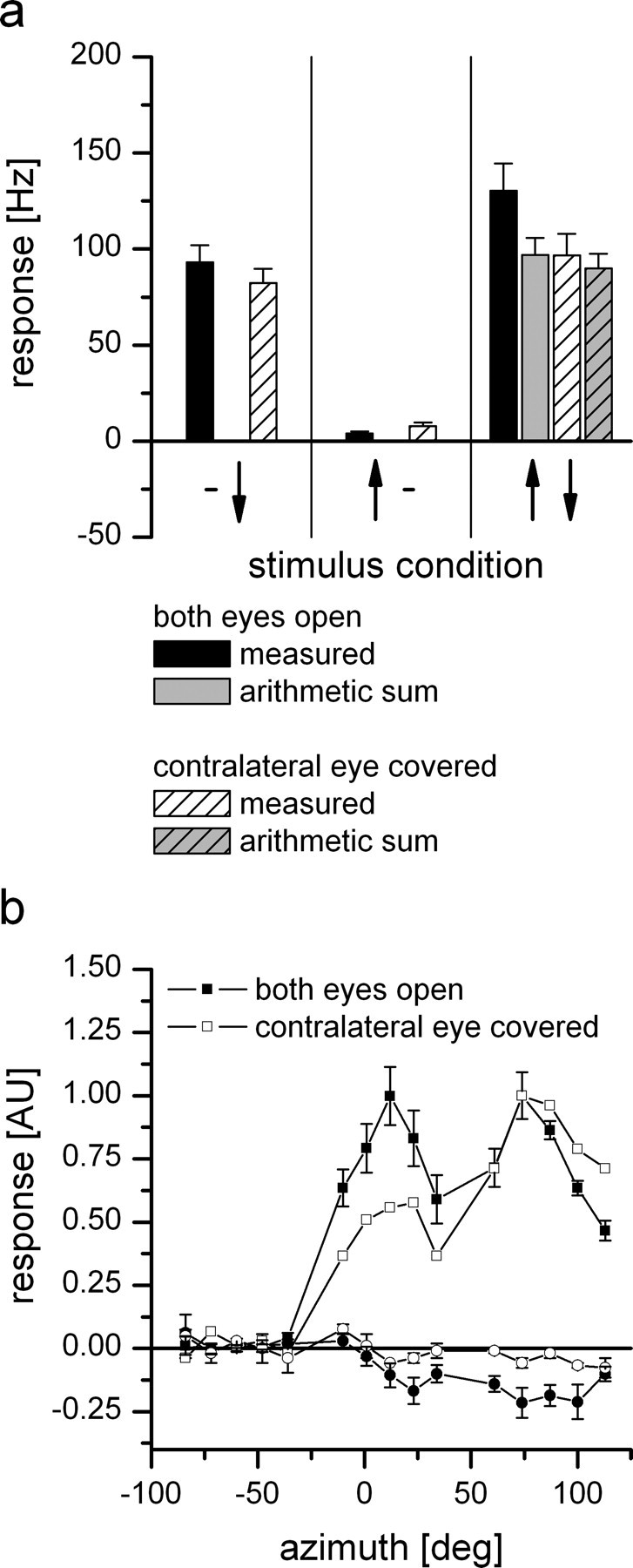
Influence of the contralateral eye on DNOVS2. With the contralateral eye covered, the responses of DNOVS2 to simultaneous motion in two sectors of the visual field (a) and to vertical motion as a function of the azimuth position (b) were measured. The patterns in the graphs refer to the response of the neurons in the following condition: black, both eyes open; white striped, left eye covered; gray, arithmetic sum of the individual stimuli with both eyes open; gray striped, arithmetic sum of the individual stimuli with the left eye closed. a, Stimulus presentation in the ipsilateral and contralateral field of view. For the individual stimuli (ipsilateral is downward and contralateral is upward motion), the responses of DNOVS2 with both eyes open and contralateral eye covered are similar. For the combined stimulus (third stimulus situation), the measured response with the contralateral eye covered (white-striped column) is less than the measured response with both eyes open (black column) but as strong as the arithmetic sum of the individual components. Data for both eyes open are the same as in Figure 3, and data for the contralateral eye covered represent the mean ± SEM from n = 3 flies. b, Response of DNOVS2 to vertical motion as a function of the azimuth position. The responses differ in the frontal field of view, in which the response for downward motion with contralateral eye covered (open symbols) is less than the response with both eyes open (filled symbols). Data for the filled symbols are the same as in Figure 2, and data for the open symbols are from n = 1 fly. AU, Arbitrary units.
To determine which tangential cells contribute to the flow field of DNOVS2, we performed double recordings from different VS cells and DNOVS2. In this series of experiments, we measured the response of DNOVS2 extracellularly while recording and injecting current in different VS cells intracellularly. DNOVS2 could be identified extracellularly because of its characteristic sensitivity for downward motion along the azimuth (Fig. 2d).
As an example, Figure 6a shows the spike events of DNOVS2 in response to current injection into a VS5 cell. Negative current injection led to a decrease and positive current to an increase of spike frequency in DNOVS2. Thus, current of both polarities was transmitted from VS5 to DNOVS2. We investigated the connectivity of all VS cells (except VS10) and DNOVS2 within one brain hemisphere. The coupling strength between different VS cells and DNOVS2 varied considerably. Current injection into VS1 and VS2 evoked nearly no change in spike frequency in DNOVS2. The strongest coupling could be found between VS5/VS6 and DNOVS2 (Fig. 6b). In addition, the spike-triggered average of the membrane potential of VS5 showed an EPSP-like potential fluctuation whenever a spike occurred in DNOVS2 (Fig. 6c). Such EPSP-like potential fluctuations were also found in VS6 (data not shown). For other VS cells, no detectable EPSPs could be found.
Figure 6.
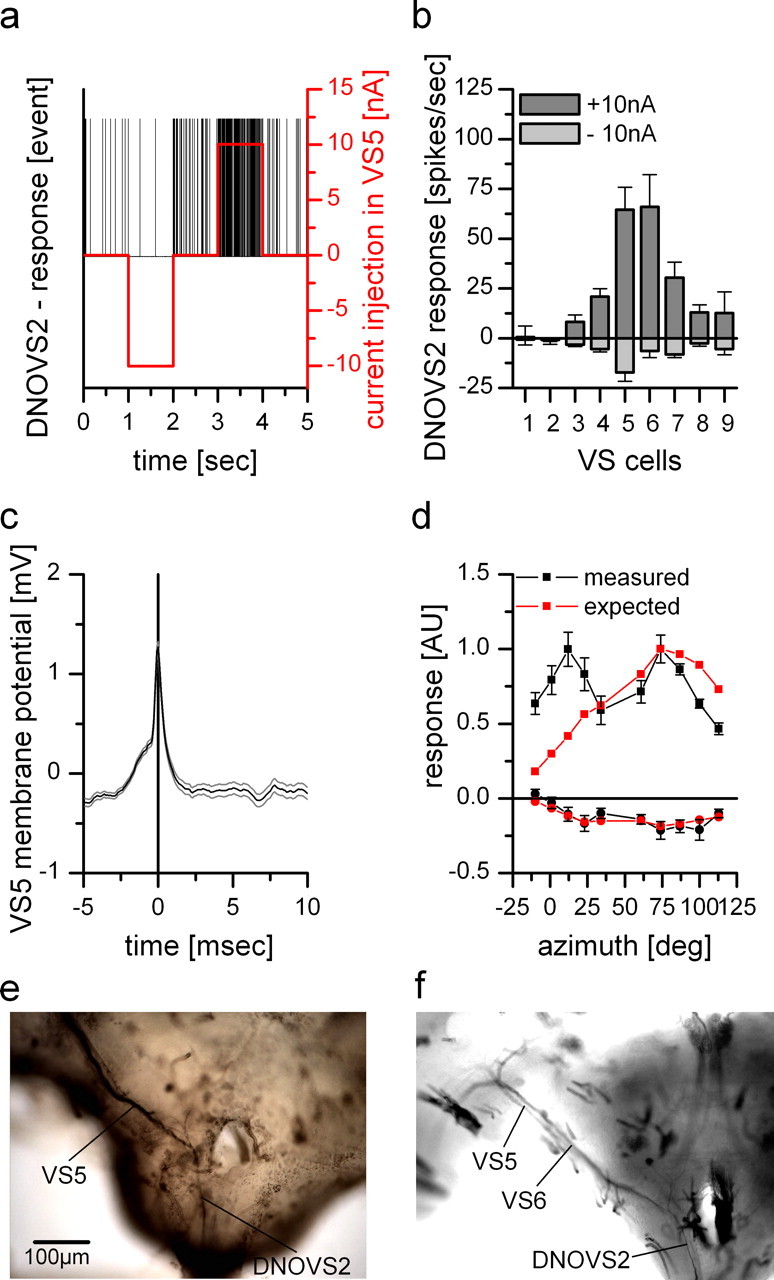
Dual recordings and dye coupling between DNOVS2 and VS cells. a, Current injection of −10 and +10 nA into VS5 led to a decrease and an increase of the spike frequency of DNOVS2, respectively. b, Current injection of −10 nA (light gray columns) and +10 nA (dark gray columns) in different VS cells elicited different levels of spike frequency decrease and increase of DNOVS2, respectively. Whereas DNOVS2 showed no responses to current injection into VS1 and VS2, it responds when current was injected into VS3–VS9. The strongest response was found for current injection into VS5 and VS6. Data represent the mean ± SEM of VS1 (n = 2), VS2 (n = 4), VS3 (n = 4), VS4 (n = 3), VS5 (n = 5), VS6 (n = 3), VS7 (n = 4), VS8 (n = 4), and VS9 (n = 2). c, Spike-triggered average of the membrane potential of a VS5 cell. A spike elicited in DNOVS2 (time point = 0) leads to a slight depolarization of the membrane potential of VS5. This spike-induced membrane shift indicates an electrical coupling between VS5 and DNOVS2. Data represent the mean ± SEM of a double recording with n = 1000 detected spike repetitions. d, Expected response of DNOVS2 (red) to vertical motion as a function of the azimuth calculated by the average response of VS1–VS9 to this stimulation (data from Haag et al., 2007) weighted by their connection strength to DNOVS2 as determined by current injection in b. The measured (black) and expected (red) response of DNOVS2 differ in the frontal field of view, in which the expected response does not show the frontal peak to downward motion. Data for the measured response are the same as in Figure 1. AU, Arbitrary units. e, Neurobiotin staining of VS5. Besides the costaining of adjacent VS cells, DNOVS2 (or DNOVS3) was found to be labeled, too (data from Haag and Borst, 2005). f, Injection of Neurobiotin into DNOVS2 led to a retrograde staining of VS6 and a weaker stained VS5 cell.
Multiplying the coupling strength between each VS cell and DNOVS2 with the response of each VS cell to vertical motion along the azimuth (data from Haag et al., 2007) gave us an estimate of the sensitivity profile for a neuron that integrates linearly the output of VS cells. The comparison between this estimated sensitivity and the measured sensitivity for vertical motion is shown in Figure 6d. For vertical motion in the ipsilateral field of view, the calculated sensitivity matches quite well the measured sensitivity of DNOVS2. Like the measured sensitivity, the calculated one shows a peak sensitivity of the cell at 75° azimuth position. In contrast, the calculated response for downward motion differs heavily for frontal stimulus positions. DNOVS2 responded with an increase of the firing rate to frontal downward motion and a maximum response was found at 10° azimuth position, whereas the calculated response was much weaker for these azimuth positions.
To provide additional evidence for the proposed connectivity between VS cells and DNOVS2, we injected fluorescein–Neurobiotin dyes into either a VS cell (Fig. 6e) (data from Haag and Borst, 2005) or into DNOVS2 (Fig. 6f). The labeled cell was identified under the fluorescence microscope. If the dye was injected into a VS5 cell (Fig. 6e), DNOVS2 was costained [Haag and Borst (2005) identified the cell as a DNOVS3 cell; however, from the dendritic anatomy, the cell matches quiet well a DNOVS2 cell]. Dye injection into DNOVS2 led to a retrograde costaining of VS6. VS5 was in this case less stained. This indicates an electrical coupling between VS5/VS6 and DNOVS2. The findings are in agreement with a previous experiment by Strausfeld and Bassemir (1985), in which they could show anterograde cobalt coupling between VS5 and VS6 onto DNOVS2. Thus, the physiological and anatomical experiments show that DNOVS2 is strongest coupled to VS5 and VS6 members of the VS class.
To map the receptive field of the neuron providing contralateral input onto DNOVS2, we recorded from DNOVS2 while presenting ipsilateral downward motion in the full monitor and contralateral upward motion in stripes (width, 12°) at different position along the azimuth (Fig. 7a). As in previous experiments, we calculated the difference between the measured response and the arithmetic sum for the contralateral stimulus at different azimuth positions (Fig. 7a). For more lateral stimulus positions, the measured response is higher than the arithmetic sum. At approximately −60°, we found a sign reversal and a switch to a sublinear summation of the individual stimuli for more frontal positions. The highest nonlinearity in the response of DNOVS2 was elicited at −87°, at which the difference between the measured response and the arithmetic sum of the individual component is highest. Thus, in the presence of ipsilateral downward motion, DNOVS2 would be most sensitive for contralateral upward motion at −87° azimuth position. This means that, in the simplest case, one neuron with peak sensitivity for upward motion at this azimuth position conveys motion information from the contralateral eye onto DNOVS2. One candidate that fulfills the requirements would be V2. This neuron has been described previously as a heterolateral spiking neuron connecting both lobula plates with preferred sensitivity for lateral upward motion (Hausen, 1977, 1981). Therefore, we recorded intracellularly and extracellularly from V2. We first measured the sensitivity of the cell for vertical motion along the azimuth (Fig. 7b). V2 responds with an increase in spike rate to lateral upward motion with a maximum sensitivity at azimuth position of −87°. Lateral downward motion elicited nearly no response in V2, which is probably attributable to the very low resting frequency of ∼1 Hz. In addition, V2 is sensitive to frontal downward motion. The shape of the sensitivity profile of V2 to upward motion along the azimuth is very similar to the nonlinear summation profile in DNOVS2 (Fig. 7c). In addition, both V2 and DNOVS2 cells are sensitive to horizontal motion. In Figure 7d, we show the tuning curves of V2 (red) and DNOVS2 (black) for different motion directions in the frontal monitor. Both cells reveal a similar tuning curve with maximal sensitivity for oblique motion between downward and rightward motion. By filling V2 and VS3 with fluorescent dyes (Alexa 488 and Alexa 568), we reconstructed the cells in AMIRA. The anatomy of V2 shows the en passant collaterals of the cell projecting to the terminal region of VS3 (Fig. 7a, arrow) and therefore to the dendritic region of DNOVS cells. Although the proof of connectivity between V2 and DNOVS2 could not yet be achieved, the physiological response properties together with the anatomy makes V2 a candidate neuron conveying motion information from the contralateral eye onto DNOVS2.
Discussion
In this study, we investigated the flow field selectivity and connectivity of DNOVS2, a prominent descending neuron in the fly visual system that is sensitive to large-field, binocular motion. Our results presented above demonstrate that DNOVS2 is tuned to a flow field that results from rotation of the fly around the longitudinal body axis. In the presence of ipsilateral downward motion, DNOVS2 is sensitive for contralateral upward motion and increases its spike rate in a nonlinear way (Fig. 3). DNOVS2 receives synaptic input from at least two different sources, from a subset of vertical-sensitive VS cells on the ipsilateral side as well as from the contralateral eye most likely via V2. Our findings above raise three questions, which we will discuss below. Can the tuning of DNOVS2 be explained by the described connectivity to VS cells and the possible connection to V2? What are the physiological differences between DNOVS2 and DNOVS1? And finally, we compare DNOVS2 with descending neurons of other species and discuss a possible functional implication.
Connectivity to LPTCs
We found that DNOVS2 integrates motion information from both eyes and, by this way, is tuned to rotational optic flow around the longitudinal body axis (Fig. 4). Our assumption about the connectivity between DNOVS2 and VS cells is based first on the change of the spike frequency of DNOVS2 in response to current injection into VS cells (Fig. 6b) and second on the dye coupling between DNOVS2 and VS5, VS6 (Fig. 6e,f). Both types of experiments support the idea that DNOVS2 is connected to VS5 and VS6. The rather weak coupling between DNOVS2 and VS3, VS4, VS7–VS9 might be attributed to the chain-like coupling of VS cells among them (Haag and Borst, 2004). For example, current injection into VS7 leads to a response in VS6, which is transmitted to DNOVS2, and therefore might not indicate a direct coupling between VS7 and DNOVS2. Accordingly, current injection into VS8 leads to an even weaker response in VS6. In addition, EPSP-like fluctuations of the membrane potential were only observable in VS5 and VS6 (Fig. 6c) but not in other VS cells. This suggested an electrical coupling of VS5, VS6, and DNOVS2, which could be confirmed by the dye coupling of Neurobiotin between these cells (Fig. 6).
Although we could not prove the connectivity between V2 and DNOVS2 experimentally (we tried to perform dual recordings), the physiological response properties of V2 (Fig. 7) suggest that motion information from the contralateral eye is conveyed by V2 onto DNOVS2 via its en passant arborization in the posterior ventral protocerebrum. From the coupling of DNOVS2 with VS5 and VS6 alone, the cell would not be able to discriminate between a translational flow field originated by an upward motion of the fly (“lift”) and a rotational flow field originated by rotation of the fly around its longitudinal axis (“roll”). However, the additional motion information from the contralateral eye enables DNOVS2 to discriminate between a translational and rotational flow field.
Physiological differences between DNOVS1 and DNOVS2
Another interesting question is how the representation of motion information differs between DNOVS cells. In a previous study, we investigated the response properties and connectivity of DNOVS1 (Haag et al., 2007). Like DNOVS2, DNOVS1 projects from the axon terminals of VS cells into the thoracic ganglion and from there onto motor neurons (Strausfeld and Bassemir, 1985; Gronenberg et al., 1995). Both cells receive visual motion input via the VS cells and from the photoreceptors of the ocelli via L-neurons (Strausfeld and Bassemir, 1985; Haag et al., 2007). Similar to DNOVS1, stimulating the ocelli with a light-emitting diode elicited a short on and off response in DNOVS2 (supplemental Fig. 1, available at www.jneurosci.org as supplemental material). Both cells have in common that they are tuned to a rotational flow field, but they also exhibit some substantial differences. In contrast to DNOVS2, DNOVS1 responds with a graded shift of the membrane potential to motion stimuli (Haag et al., 2007). Ipsilateral downward and frontal upward motion elicited the strongest response in DNOVS1, resulting in a tuning to a rotational flow field, in which the pole of rotation is located at 15° azimuth. DNOVS2 is tuned to a rotational flow field with a pole of rotation at 0° azimuth. Thus, different axes of rotation are represented by different descending neurons. Whether this is also the case for other descending neurons, such as DNOVS3, is still not known. Interestingly, the tuning of the cells is achieved by different kind of synaptic integration. In DNOVS2, the binocular input is integrated in a nonlinear way, whereas in DNOVS1, a linear integration takes place (Haag et al., 2007). As mentioned above, the spike threshold of DNOVS2 is probably responsible for the nonlinear integration. A linear as well as a nonlinear integration of binocular optic flow has been reported for spiking descending neurons of the fly responding best to image expansion (Borst, 1991). This raises the question whether a supralinear integration is a general feature of spiking neurons only, or whether it could be also achieved in graded potential neurons but by other mechanisms.
Another difference between DNOVS1 and DNOVS2 is their connectivity pattern with VS cells. Whereas DNOVS2 is coupled most strongly to VS5 and VS6 (Fig. 6), current injections and correlation of signals in DNOVS1 and VS cells revealed the strongest coupling of DNOVS1 with VS7 and VS8 (Haag et al., 2007). Lateral VS cells (VS7, VS8) are more sensitive for downward motion at more laterocaudal positions (Krapp et al., 1998), which is also the case for DNOVS1. Thus, different VS cells excite DNOVS1 and DNOVS2 strongest, resulting in different sensitivity profiles for vertical motion along the azimuth.
Functional implication
Descending neurons that are directionally sensitive to wide-field motion have been reported in a number of other insects, such as moths (Collett and Blest, 1966; Rind, 1983), locusts (Kien, 1974; Rowell and Reichert, 1986), dragonflies (Olberg, 1981a,b), and bees (Ibbotson and Goodman, 1990; Ibbotson, 1991). One intensively studied example in locusts is the DCMD (descending contralateral movement detector), which is connected to the LGMD (lobula giant motion detector) and might play an important role in collision avoidance (Hatsopoulos et al., 1995; Judge and Rind, 1997) (for review, see Rind and Simmons, 1999). LGMD/DCMD are sensitive for looming stimuli, whereas DNOVS2 was excited strongest by a rotational-like stimulus. Thus, DNOVS2 is probably not involved in avoiding a collision in flies.
In bees, two descending neurons (DNIV2 and DNIV4) were found that share anatomical and physiological similarities with DNOVS2 (Ibbotson and Goodman, 1990). Like DNOVS2, DNIV2 and DNIV4 have their dendritic as well as their axonal arborization confined to the ipsilateral side of the brain and the thoracic ganglion, respectively. DNIV2 and DNIV4 are spiking neurons excited strongest by a movement around the longitudinal body axes. Ibbotson and Goodman (1990) suggested that DNIV2 and DNIV4 are involved in the correction of roll deviation, which could also be the case for DNOVS2.
For both DNOVS cells, it is known that they are dye coupled to neck motor neurons of the frontal nerve (Gronenberg et al., 1995). These frontal nerve neck neurons in turn innervate the large sclerite depressor muscle involved in head-roll movements (Strausfeld et al., 1987; Gilbert et al., 1995). Previous studies showed that motor neurons of the frontal nerve are motion sensitive (Milde et al., 1987; Gronenberg et al., 1995; Huston and Krapp, 2003; Krapp and Huston, 2005). Although the number of neck muscle and motor neurons is manageable (Milde et al., 1987; Strausfeld et al., 1987), the neural circuit as well as the computations underlying these optomotor responses is complex and far from being understood.
However, the connections to neck motor neurons suggest DNOVS1 and DNOVS2 to be involved in the gaze stabilization during flight, which results in an improved condition of vision (Schilstra and van Hateren, 1999; van Hateren and Schilstra, 1999). In free flight, blowflies execute series of saccadic turns with angular velocities of up to several thousand degrees per second; between saccades, the gaze is kept stable (Schilstra and van Hateren, 1998, 1999; van Hateren and Schilstra, 1999). Whereas DNOVS1 ends in the anterior prothoracic ganglion, DNOVS2 extends through prothoracic, mesothoracic, and metathoracic ganglia (Strausfeld and Bassemir, 1985). Thus, with projections in all three thoracic ganglia, DNOVS2 may participate, on one hand, in the coordination of gaze stabilization via neck motor neurons; on the other hand, DNOVS2 could initiate body saccade. Here again, an additional description of the projections is necessary for a complete understanding of the role of DNOVS2 in visually driven behavior.
Footnotes
This work was supported by the Max-Planck-Society, Deutsche Forschungsgemeinschaft Grant GRK 1091 (A.W.), and by a grant from the Bundesministerium für Bildung und Forschung to the Bernstein Center for Computational Neuroscience Munich (A.B.). We are grateful to Renate Gleich and Ursula Weber for excellent technical assistance.
References
- Beersma DGM, Stavenga DG, Kuiper JW. Retinal lattice, visual field and binocularities in flies. J Comp Physiol A Neuroethol Sens Neural Behav Physiol. 1977;119:207–220. [Google Scholar]
- Borst A. Fly visual interneurons responsive to image expansion. Zool Jb Physiol. 1991;95:305–313. [Google Scholar]
- Borst A, Bahde S. Spatio-temporal integration of motion: a simple strategy for safe landing in flies. Naturwissenschaften. 1988;75:265–267. [Google Scholar]
- Borst A, Egelhaaf M. In vivo imaging of calcium accumulation in fly interneurons as elicited by visual motion stimulation. Proc Natl Acad Sci USA. 1992;89:4139–4143. doi: 10.1073/pnas.89.9.4139. [DOI] [PMC free article] [PubMed] [Google Scholar]
- Borst A, Haag J. Neural networks in the cockpit of the fly. J Comp Physiol A Neuroethol Sens Neural Behav Physiol. 2002;188:419–437. doi: 10.1007/s00359-002-0316-8. [DOI] [PubMed] [Google Scholar]
- Collett TS, Blest AD. Binocular, directionally-selective neurons, possibly involved in the optomotor response of insects. Nature. 1966;212:1330–1333. doi: 10.1038/2121330a0. [DOI] [PubMed] [Google Scholar]
- Cuntz H, Haag J, Fortsner F, Segev I, Borst A. Robust coding of flow-field parameters by axo-axonal gap junctions between fly visual interneurons. Proc Natl Acad Sci USA. 2007;104:10229–10233. doi: 10.1073/pnas.0703697104. [DOI] [PMC free article] [PubMed] [Google Scholar]
- Denk W, Strickler JH, Webb WW. Two-photon laser scanning fluorescence microscopy. Science. 1990;248:73–76. doi: 10.1126/science.2321027. [DOI] [PubMed] [Google Scholar]
- Farrow K. München: Ludwig-Maximilians-Universität; 2005. Lateral interactions and receptive field structure of lobula plate tangential cells in the blowfly. PhD thesis. [Google Scholar]
- Farrow K, Haag J, Borst A. Input organization of multifunctional motion-sensitive neurons in the blowfly. J Neurosci. 2003;23:9805–9811. doi: 10.1523/JNEUROSCI.23-30-09805.2003. [DOI] [PMC free article] [PubMed] [Google Scholar]
- Farrow K, Borst A, Haag J. Sharing receptive fields with your neighbors: tuning the vertical system cells to wide field motion. J Neurosci. 2005;25:3985–3993. doi: 10.1523/JNEUROSCI.0168-05.2005. [DOI] [PMC free article] [PubMed] [Google Scholar]
- Farrow K, Haag J, Borst A. Nonlinear, binocular interactions underlying flow field selectivity of a motion-sensitive neuron. Nat Neurosci. 2006;9:1312–1320. doi: 10.1038/nn1769. [DOI] [PubMed] [Google Scholar]
- Franz MO, Krapp HG. Wide-field, motion-sensitive neurons and matched filters for optic flow fields. Biol Cybern. 2000;83:185–197. doi: 10.1007/s004220000163. [DOI] [PubMed] [Google Scholar]
- Frye MA, Dickinson MH. Fly flight: a model for the neural control of complex behavior. Neuron. 2001;32:385–388. doi: 10.1016/s0896-6273(01)00490-1. [DOI] [PubMed] [Google Scholar]
- Gilbert C, Gronenberg W, Strausfeld NJ. Oculomotor control in calliphorid flies: head movements during activation and inhibition of neck motor neurons corroborate neuroanatomical predictions. J Comp Neurol. 1995;361:285–297. doi: 10.1002/cne.903610207. [DOI] [PubMed] [Google Scholar]
- Gronenberg W, Strausfeld NJ. Descending pathways connecting the male-specific visual system of flies to the neck and flight motor. J Comp Physiol A Neuroethol Sens Neural Behav Physiol. 1991;169:413–426. doi: 10.1007/BF00197654. [DOI] [PubMed] [Google Scholar]
- Gronenberg W, Milde JJ, Strausfeld NJ. Oculomotor control in calliphorid flies: organization of descending neurons to neck motor neurons responding to visual stimuli. J Comp Neurol. 1995;361:267–284. doi: 10.1002/cne.903610206. [DOI] [PubMed] [Google Scholar]
- Haag J, Borst A. Recurrent network interactions underlying flow-field selectivity of visual interneurons. J Neurosci. 2001;21:5685–5692. doi: 10.1523/JNEUROSCI.21-15-05685.2001. [DOI] [PMC free article] [PubMed] [Google Scholar]
- Haag J, Borst A. Dendro-dendritic interactions between motion-sensitive large-field neurons in the fly. J Neurosci. 2002;22:3227–3233. doi: 10.1523/JNEUROSCI.22-08-03227.2002. [DOI] [PMC free article] [PubMed] [Google Scholar]
- Haag J, Borst A. Orientation tuning of motion-sensitive neurons shaped by vertical-horizontal network interactions. J Comp Physiol A Neuroethol Sens Neural Behav Physiol. 2003;189:363–370. doi: 10.1007/s00359-003-0410-6. [DOI] [PubMed] [Google Scholar]
- Haag J, Borst A. Neural mechanism underlying complex receptive field properties of motion-sensitive interneurons. Nat Neurosci. 2004;7:628–634. doi: 10.1038/nn1245. [DOI] [PubMed] [Google Scholar]
- Haag J, Borst A. Dye-coupling visualizes networks of large-field motion-sensitive neurons in the fly. J Comp Physiol A Neuroethol Sens Neural Behav Physiol. 2005;191:445–454. doi: 10.1007/s00359-005-0605-0. [DOI] [PubMed] [Google Scholar]
- Haag J, Borst A. Reciprocal inhibitory connections within a neural network for rotational optic-flow processing. Front Neurosci. 2007;1:111–121. doi: 10.3389/neuro.01.1.1.008.2007. [DOI] [PMC free article] [PubMed] [Google Scholar]
- Haag J, Egelhaaf M, Borst A. Dendritic integration of motion information in visual interneurons of the blowfly. Neurosci Lett. 1992;140:173–176. doi: 10.1016/0304-3940(92)90095-o. [DOI] [PubMed] [Google Scholar]
- Haag J, Denk W, Borst A. Fly motion vision is based on Reichardt detectors regardless of the signal-to-noise ratio. Proc Natl Acad Sci USA. 2004;101:16333–16338. doi: 10.1073/pnas.0407368101. [DOI] [PMC free article] [PubMed] [Google Scholar]
- Haag J, Wertz A, Borst A. Integration of lobula plate output signals by DNOVS1, an identified premotor descending neuron. J Neurosci. 2007;27:1992–2000. doi: 10.1523/JNEUROSCI.4393-06.2007. [DOI] [PMC free article] [PubMed] [Google Scholar]
- Hatsopoulos N, Gabbiani F, Laurent G. Elementary computation of object approach by a wide-field visual neuron. Science. 1995;270:1000–1003. doi: 10.1126/science.270.5238.1000. [DOI] [PubMed] [Google Scholar]
- Hausen K. Functional characterization and anatomical identification of motion sensitive neurons in the lobula plate of the blowfly Calliphora erythrocephala. Z Naturforsch. 1976;31c:629–c633. [Google Scholar]
- Hausen K. Tübingen: Eberhard-Karls-Universität zu; 1977. Struktur, Funktion und Konnektivität bewegungsempfindlicher Interneurone im dritten optischen Neuropil der Schmeiβfliege Calliphora erythrocephala. PhD thesis. [Google Scholar]
- Hausen K. Monocular and binocular computation of motion in the lobula plate of the fly. Verh Dtsch Zool Ges. 1981;74:49–70. [Google Scholar]
- Hausen K. Motion sensitive interneurons in the optomotor system of the fly. I. The horizontal cells: structure and signals. Biol Cybern. 1982;45:143–156. [Google Scholar]
- Hausen K. The lobula-complex of the fly: structure, function and significance in visual behaviour. In: Ali MA, editor. Photoreception and vision in invertebrates. London: Plenum; 1984. pp. 523–559. [Google Scholar]
- Hausen K, Egelhaaf M. Neural mechanisms of visual course control in insects. In: Stavenga DG, Hardie RC, editors. Facets of vision. Berlin: Springer; 1989. pp. 391–424. [Google Scholar]
- Hengstenberg R. Roll-stabilization during flight of the blowfly's head and body mechanical and visual cues. In: Varjú D, Schnitzler H, editors. Localization and orientation in biology and engineering. Berlin: Springer; 1984. pp. 121–134. [Google Scholar]
- Hengstenberg R. Mechanosensory control of compensatory head roll during flight in the blowfly Calliphora erythrocephala meig. J Comp Physiol A Neuroethol Sens Neural Behav Physiol. 1988;163:151–165. [Google Scholar]
- Hengstenberg R. Gaze control in the blowfly Calliphora: a multisensory, two-stage integration process. Semin Neurosci. 1991;3:19–29. [Google Scholar]
- Hengstenberg R, Hausen K, Hengstenberg B. The number and structure of giant vertical cells (VS) in the lobula plate of the blowfly Calliphora erytrocephala. J Comp Physiol A Neuroethol Sens Neural Behav Physiol. 1982;149:163–177. [Google Scholar]
- Horstmann W, Egelhaaf M, Warzecha AK. Synaptic interaction increase optic flow specificity. Eur J Neurosci. 2000;12:2157–2165. doi: 10.1046/j.1460-9568.2000.00094.x. [DOI] [PubMed] [Google Scholar]
- Huston SJ, Krapp HG. Visual receptive field of a fly neck motorneuron. In: Elsner N, Schnitzler HU, editors. Goettingen neurobiology report 2003. Stuttgart, Germany: Thieme; 2003. p. 559. [Google Scholar]
- Ibbotson MR. A motion-sensitive visual descending neurone in Apis mellifera monitoring translatory flow-fields in the horizontal plane. J Exp Biol. 1991;157:573–577. [Google Scholar]
- Ibbotson MR, Goodman LJ. Response characteristics of four wide-field motion-sensitive descending interneurones in Apis mellifera. J Exp Biol. 1990;148:255–279. [Google Scholar]
- Judge S, Rind FC. The locust DCMD neuron, a movement-detecting neurone tightly tuned to collision trajectories. J Exp Biol. 1997;200:2209–2216. doi: 10.1242/jeb.200.16.2209. [DOI] [PubMed] [Google Scholar]
- Kalb J, Egelhaaf M, Kurtz R. Robust integration of motion information in the fly visual system revealed by single cell photoablation. J Neurosci. 2006;26:7898–7906. doi: 10.1523/JNEUROSCI.1327-06.2006. [DOI] [PMC free article] [PubMed] [Google Scholar]
- Karmeier K, Krapp HG, Egelhaaf M. Robustness of the tuning of fly visual interneurons to rotatory optic flow. J Neurophysiol. 2003;90:1626–1634. doi: 10.1152/jn.00234.2003. [DOI] [PubMed] [Google Scholar]
- Kien J. Sensory integration in the locust optomotor system. II. Direction selective neurons in the circumoesophageal connectives and the optic lobe. Vision Res. 1974;14:1255–1268. doi: 10.1016/0042-6989(74)90224-7. [DOI] [PubMed] [Google Scholar]
- Krapp HG, Hengstenberg R. Estimation of self-motion by optic flow processing in single visual interneurons. Nature. 1996;384:463–466. doi: 10.1038/384463a0. [DOI] [PubMed] [Google Scholar]
- Krapp HG, Huston SJ. Encoding self-motion: from visual receptive fields to motor neuron response maps. Proceedings of the 30th Goettingen Neurobiology Conference, Sixth Meeting of the German Neuroscience Society; February; Goettingen, Germany. 2005. [Google Scholar]
- Krapp HG, Hengstenberg B, Hengstenberg R. Dendritic structure and receptive-field organization of optic flow processing interneurons in the fly. J Neurophysiol. 1998;79:1902–1917. doi: 10.1152/jn.1998.79.4.1902. [DOI] [PubMed] [Google Scholar]
- Milde JJ, Seyan HS, Strausfeld NJ. The neck motor system of the fly Calliphora erythrocephala. 2. Sensory organization. J Comp Physiol A Neuroethol Sens Neural Behav Physiol. 1987;160:225–238. [Google Scholar]
- Olberg RM. Object and self movement detectors in the ventral nerve cord of the dragonfly. J Comp Physiol A Neuroethol Sens Neural Behav Physiol. 1981a;141:327–334. [Google Scholar]
- Olberg RM. Parallel encoding of direction of wind, head, abdomen and visual pattern movement by single interneurons in the dragonfly. J Comp Physiol A Neuroethol Sens Neural Behav Physiol. 1981b;142:27–41. [Google Scholar]
- Rind FC. A directionally selective motion-detection neuron in the brain of a moth. J Exp Biol. 1983;102:253–271. [Google Scholar]
- Rind FC, Simmons PJ. Seeing what is coming: building collision-sensitive neurones. Trends Neurosci. 1999;22:215–220. doi: 10.1016/s0166-2236(98)01332-0. [DOI] [PubMed] [Google Scholar]
- Rowell CHF, Reichert M. Three descending interneurons reporting deviation from course in the locust. II. Physiology J Comp Physiol A Neuroethol Sens Neural Behav Physiol. 1986;158:775–794. doi: 10.1007/BF01324821. [DOI] [PubMed] [Google Scholar]
- Schilstra C, van Hateren JH. Stabilizing gaze in flying blowflies. Nature. 1998;395:654. doi: 10.1038/27114. [DOI] [PubMed] [Google Scholar]
- Schilstra C, van Hateren JH. Blowfly flight and optic flow. I. Thorax kinematics and flight dynamics. J Exp Biol. 1999;202:1481–1490. doi: 10.1242/jeb.202.11.1481. [DOI] [PubMed] [Google Scholar]
- Schuppe H, Hengstenberg R. Optical properties of the ocelli of Calliphora erythrocephala and their role in the dorsal light response. J Comp Physiol A Neuroethol Sens Neural Behav Physiol. 1993;173:143–149. [Google Scholar]
- Single S, Borst A. Dendritic integration and its role in computing image velocity. Science. 1998;281:1848–1850. doi: 10.1126/science.281.5384.1848. [DOI] [PubMed] [Google Scholar]
- Srinivasan MV, Zhang S. Visual motor computations in insects. Annu Rev Neurosci. 2004;27:679–696. doi: 10.1146/annurev.neuro.27.070203.144343. [DOI] [PubMed] [Google Scholar]
- Strausfeld NJ, Bassemir UK. Lobula plate and ocellar interneurons converge onto a cluster of descending neurons leading to neck and leg motor neuropil in Calliphora erythrocephala. Cell Tissue Res. 1985;240:617–640. [Google Scholar]
- Strausfeld NJ, Seyan HS. Convergence of visual, haltere and prosternal inputs at neck motor neurons of Calliphora erythrocephala. Cell Tissue Res. 1985;240:601–615. [Google Scholar]
- Strausfeld NJ, Seyan HS, Milde JJ. The neck motor system of the fly Calliphora erythrocephala. 1. Muscles and motor neurons. J Comp Physiol A Neuroethol Sens Neural Behav Physiol. 1987;160:205–224. [Google Scholar]
- van Hateren JH, Schilstra C. Blowfly flight and optic flow. II. Head movements during flight. J Exp Biol. 1999;202:1491–1500. doi: 10.1242/jeb.202.11.1491. [DOI] [PubMed] [Google Scholar]